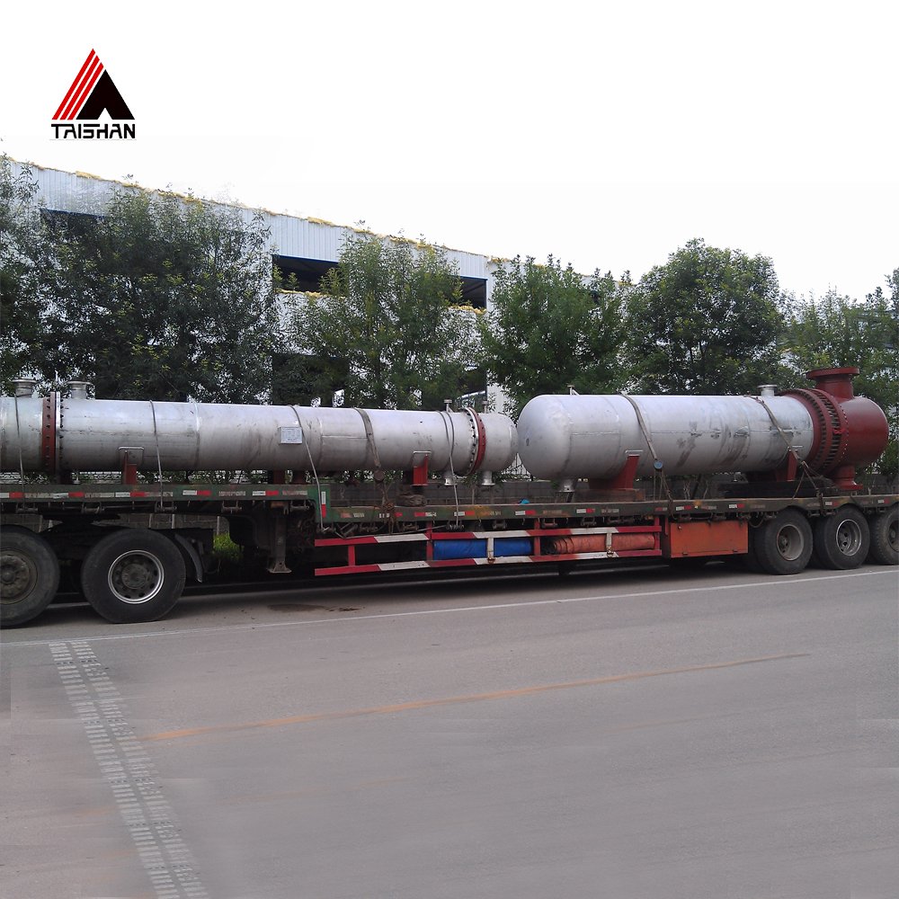
When purchasing a shell and tube heat exchanger, defining design pressure, design temperature, and corrosion allowance correctly is non-negotiable. These three values dictate the exchanger’s mechanical design, material selection, wall thickness, compliance with ASME or international codes, and ultimately its safety and service life. If these parameters are misjudged or left vague in procurement specifications, you risk underbuilt equipment, unplanned failures, code violations, or even catastrophic incidents. Clear definition of these parameters ensures the manufacturer delivers a heat exchanger tailored to your process needs—safe, reliable, and cost-effective.
Design pressure is the maximum pressure that any part of the shell and tube exchanger must withstand under full-load operating conditions, including possible surges. Design temperature is the maximum (or minimum) metal temperature expected under pressure, determining material selection and allowable stress. Corrosion allowance is an additional wall thickness added to accommodate material loss due to corrosion or erosion over the exchanger’s life. These values must be specified separately for the shell side and tube side.
As a buyer, your job is not just to provide process data, but to define these design parameters in a way that aligns with engineering codes and your plant’s safety philosophy. Here’s how to do it right.
Design pressure and temperature are provided by the heat exchanger supplier based on best guesses.False
Design pressure and temperature must be defined by the purchaser based on the process conditions, safety margins, and applicable design codes.
Step 1: Define Design Pressure for Both Shell and Tube Sides
Definition:
Design pressure is the maximum internal pressure that any pressure-retaining component (shell, tubes, heads, nozzles) must safely withstand under the specified design temperature. It forms the basis for wall thickness calculations and pressure vessel code compliance (e.g., ASME Section VIII).
How to Define It:
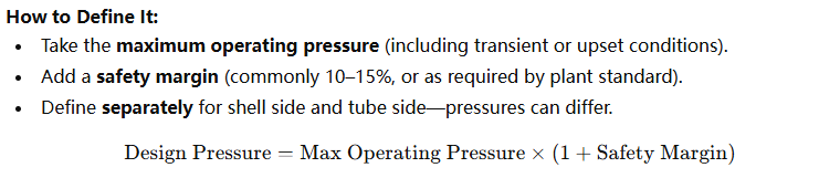
Example:
| Side | Operating Pressure (barg) | Safety Margin | Design Pressure |
|---|---|---|---|
| Shell Side | 8 | 15% | 9.2 barg |
| Tube Side | 16 | 10% | 17.6 barg |
Practical Tip:
Always check if hydrostatic head or pump shutoff pressure must be included. For condensers or vacuum service, define external pressure (e.g., full vacuum: -1.0 barg).
Step 2: Define Design Temperature for Shell and Tube Sides
Definition:
Design temperature is the maximum (or minimum) metal temperature that pressure parts are expected to experience while under pressure. It’s used to determine material strength, select temperature-rated components (gaskets, seals), and ensure thermal stability.
How to Define It:
- Use the highest fluid temperature for each side, plus a design margin (typically +15–30°C).
- Consider start-up, shutdown, and heat tracing scenarios.
- Define separately for shell and tube sides.
Example:
| Side | Operating Temp (°C) | Design Margin | Design Temperature |
|---|---|---|---|
| Shell Side | 150 | +25°C | 175°C |
| Tube Side | 210 | +20°C | 230°C |
Minimum Design Temperature:
If the exchanger will experience low temperatures during shutdown or storage, specify minimum design temperature to avoid brittle fracture risk.
| Application | Min Design Temp |
|---|---|
| Outdoor service | -20°C to -40°C |
| Cryogenic duty | -100°C or lower |
Step 3: Define Corrosion Allowance (CA)
Definition:
Corrosion allowance is the extra metal thickness intentionally added to shell, tubes, heads, and other wetted components to compensate for expected material loss due to corrosion, erosion, or fouling over time.
How to Define It:
- Based on fluid corrosivity, expected service life, and cleaning frequency.
- CA is typically added only to carbon steel components, but may be specified for stainless or exotic alloys if minor corrosion is still expected.
| Fluid Type | Recommended CA |
|---|---|
| Clean steam, potable water | 0 mm |
| Treated boiler water | 1 mm |
| Cooling tower water | 1.5–3 mm |
| Hydrocarbons w/ H₂S | 3–6 mm |
| Seawater | 2–3 mm |
Example:
| Component | Material | Fluid Type | Corrosion Allowance |
|---|---|---|---|
| Shell | Carbon Steel | Cooling water | 3 mm |
| Tubes | 316L Stainless | Steam | 0 mm |
| Tubesheets | Cladded CS | Crude oil | 3 mm (on CS side) |
Tip:
Corrosion allowance does not replace corrosion resistance. For highly corrosive fluids, select corrosion-resistant alloys like Hastelloy, Incoloy, or titanium instead of just adding CA.
Corrosion allowance can compensate for the use of incorrect materials in corrosive services.False
Corrosion allowance only prolongs life against expected corrosion but does not make unsuitable materials safe for corrosive applications.
Data Sheet Example for Purchasing
Here’s how you would specify these values on your purchase data sheet:
| Item | Shell Side | Tube Side |
|---|---|---|
| Design Pressure | 10 barg | 16 barg |
| Design Temperature | 175°C | 230°C |
| Min Design Temp | -20°C | -10°C |
| Corrosion Allowance | 3 mm | 0 mm |
| Operating Pressure | 8 barg | 14 barg |
| Operating Temp | 150°C | 210°C |
| Fluid Type | Cooling water | Superheated steam |
| Material (Suggested) | Carbon Steel | 316L Stainless Steel |
Why These Parameters Matter in Procurement
| Design Parameter | Impacts |
|---|---|
| Design Pressure | Wall thickness, flange rating, code calculations |
| Design Temperature | Material selection, gasket selection, stress calc |
| Corrosion Allowance | Added thickness, lifespan, maintenance schedule |
Omitting or incorrectly specifying any of these may:
- Lead to non-code-compliant equipment
- Increase risk of mechanical failure
- Shorten service life drastically
- Void warranties or insurance coverage
Conclusion
Defining design pressure, design temperature, and corrosion allowance correctly is a critical step in purchasing a safe, reliable, and code-compliant shell and tube heat exchanger. These values are not optional or “best guesses”—they must be carefully calculated and clearly communicated to your supplier.
💡 Always define these parameters separately for shell and tube sides, consult your process engineer, and align with ASME or regional code requirements.
You can use the same design pressure and temperature for both sides of a heat exchanger to simplify design.False
Shell and tube sides often have different pressures and temperatures; each must be evaluated and specified individually for safe and accurate design.
📩 Need help preparing a compliant specification for your shell and tube heat exchanger purchase?
Contact our engineering experts today—we’ll help you define the correct design parameters to meet your exact process and safety needs.
References
- ASME Boiler and Pressure Vessel Code (Section VIII) – ASME
- TEMA Standards Overview – Tubular Exchanger Manufacturers Association
- API 660 – Shell-and-Tube Heat Exchangers – American Petroleum Institute
- Design Considerations for Shell and Tube Heat Exchangers – Chemical Engineering Resources
- Understanding Design Pressure and Temperature – EnggCyclopedia
- Corrosion Allowance Explained – Corrosionpedia
- Heat Exchanger Material Selection Guide – Matmatch
- Shell and Tube Heat Exchanger Basics – Bright Hub Engineering
- Inspection Guidelines for Pressure Vessels – Inspectioneering
- Mechanical Design of Heat Exchangers – ScienceDirect