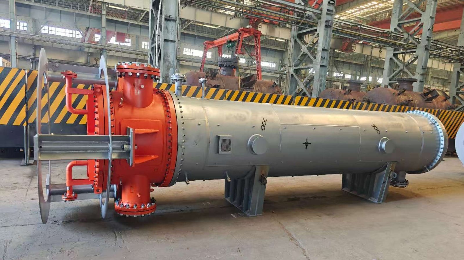
Shell and tube heat exchangers are widely used across industries like chemical processing, oil refining, HVAC, power generation, and pharmaceuticals due to their robust design and high thermal efficiency. However, the complexity and variability in their configurations often confuse buyers and engineers, leading to incorrect selections that cause reduced heat transfer performance, operational inefficiencies, and increased maintenance costs. The choice of the right configuration depends on many factors like operating pressure, temperature, thermal expansion, fouling tendencies, and cleaning frequency. This article provides a comprehensive technical breakdown of all major shell and tube configurations and helps you select the best one for your application.
There are five primary shell and tube heat exchanger design configurations: fixed tube sheet, U-tube, floating head, kettle type, and pull-through floating head. The most suitable configuration depends on operating conditions, ease of maintenance, fouling characteristics, and thermal expansion demands. For example, U-tube exchangers are compact and cost-effective but harder to clean, while floating head types handle thermal expansion better and allow easy cleaning of both tube and shell sides.
Choosing the wrong configuration can lead to mechanical failures from thermal stress or operational inefficiencies due to fouling and poor cleanability. That’s why understanding each configuration in detail, along with its pros, cons, and typical application environments, is vital. Keep reading to determine which shell and tube heat exchanger design aligns best with your system requirements.
U-tube heat exchangers are easier to clean than straight tube designs.False
U-tube designs are harder to clean on the tube side because the bend makes mechanical cleaning difficult.
Floating head heat exchangers can handle differential thermal expansion between shell and tubes.True
Floating head designs allow free movement of the tube bundle to relieve thermal stresses caused by temperature differences.
Understanding the Five Core Shell and Tube Heat Exchanger Designs
Shell and tube heat exchangers can be custom-designed in a variety of ways, but most commercial units fall into five main configurations. Each has distinct structural elements and functional characteristics. The following table provides a comparative overview:
| Configuration | Description | Advantages | Limitations | Typical Applications |
|---|---|---|---|---|
| Fixed Tube Sheet | Tubes are permanently attached (welded or expanded) to the tube sheets at both ends. | Simple, cost-effective, good for clean fluids | Difficult to clean tube side, thermal expansion stress | Steam heaters, lubricating oil coolers |
| U-Tube | Tubes are bent into a “U” shape and fixed at one end only. | Allows for thermal expansion, compact design | Harder to clean tube side, cannot handle dirty fluids | Economizers, heat recovery units |
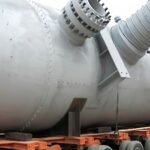
| Floating Head | One end of the tube bundle is fixed, the other end floats inside the shell. | Handles thermal expansion, easy cleaning | More expensive, complex construction | High-temperature, high-pressure services |
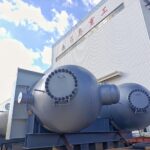
| Kettle Type | Shell has a large reservoir (“kettle”) with a horizontal tube bundle immersed inside. | Great for phase-change (condensation or evaporation), large heat duty | Bulky, high initial cost | Reboilers, condensers |
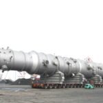
| Pull-Through Floating Head | Modified floating head that allows the entire tube bundle to be pulled out | Best cleanability, excellent for fouling fluids | Highest cost, larger size | Crude oil heating, waste heat recovery |
Let us now explore each configuration with engineering depth and real-world considerations.
Fixed Tube Sheet Exchanger
Fixed tube sheet designs are the most economical and are suitable where no differential thermal expansion is expected between shell and tubes. In this design, both ends of the tubes are rigidly attached to the tube sheets, which are welded to the shell. As a result, they are suitable only when the shell and tube materials have similar thermal expansion coefficients.
Key Technical Considerations:
- Design Pressure: Up to 50 bar
- Design Temperature: Up to 400°C
- Tube Cleaning: Only outside (shell side) cleaning possible
- Thermal Stress: High due to fixed nature; expansion joints may be needed
Best Used For:
- Clean fluids with no fouling
- Applications with no significant thermal differential
- Simple water heating or cooling applications
U-Tube Heat Exchanger
U-tube designs use a single tube sheet and bend tubes back in a U shape, allowing the bundle to expand and contract freely. This design avoids the need for expansion joints, making it ideal for high-temperature differential applications.
Technical Details:
- Max Tube Length: Shorter than straight tubes
- Thermal Expansion: Excellent tolerance due to U-bend
- Tube Cleaning: Difficult on the inside bend side
- Tube Replacement: Partial bundle replacement is complicated
Ideal Scenarios:
- Moderate fouling fluids (outside tube side)
- Compact installations with limited space
- Heat recovery units in industrial HVAC
Floating Head Exchanger
In this configuration, one end of the tube bundle is fixed while the other is free to move inside the shell. This floating head moves axially, reducing thermal stress and allowing easy disassembly for cleaning.
Engineering Performance:
- Design Life: Long, due to low thermal stress
- Maintenance: Easy to clean both shell and tube sides
- Leakage Risk: Higher due to gasketed head
- Cost: Higher than fixed or U-tube due to complexity
Best Use Cases:
- Refineries with frequent cleaning cycles
- Fouling-prone fluids
- High-pressure and high-temperature chemical processes
Kettle Type Reboiler Design
A kettle reboiler is a horizontal exchanger used for vaporizing part of the bottom product in a distillation column. It consists of a large shell (kettle) where liquid boils over the immersed tube bundle.
Specialized Attributes:
- Operation Mode: Always horizontal
- Two-phase Flow: Excellent for vapor-liquid phase change
- Capacity: Can handle large volumes
- Control Complexity: Requires proper vapor disengagement design
Best Suited For:
- Distillation column bottoms
- Ammonia and methanol plants
- Low-pressure boiling fluids
Pull-Through Floating Head Exchanger
A modified version of the floating head that allows the tube bundle to be pulled entirely through the shell for maintenance. Offers excellent accessibility and long-term reliability.
Engineering Specifications:
- Cleaning: Best possible
- Inspection Access: 100% of internal surfaces
- Size: Requires more space and support
- Cost: Most expensive option
Perfect For:
- High-fouling services (e.g., crude oil preheating)
- Shutdown-sensitive industries (e.g., petrochemicals)
- Applications where hygiene and cleaning are critical (e.g., food and pharma)
Comparative Engineering Chart
Here is a visual performance comparison chart based on four critical parameters: thermal expansion tolerance, ease of maintenance, cost, and fouling resistance.
| Configuration | Thermal Expansion | Maintenance | Cost | Fouling Resistance |
|---|---|---|---|---|
| Fixed Tube Sheet | Low | Low | Low | Low |
| U-Tube | Medium | Medium-Low | Medium | Medium |
| Floating Head | High | High | High | High |
| Kettle Type | Medium | Medium | High | Medium |
| Pull-Through Floating Head | Highest | Highest | Very High | Very High |
Which Design is Most Suitable for Your Application?
The selection must be tailored to the exact process parameters of your plant. Let’s use a simplified decision matrix based on four common industrial conditions:
| Criteria | Option 1: High Temp, Clean Fluids | Option 2: High Fouling | Option 3: Moderate Temp, Budget-Constrained | Option 4: Phase Change |
|---|---|---|---|---|
| Recommended Design | U-Tube | Floating Head or Pull-Through | Fixed Tube Sheet | Kettle Type |
When choosing the right configuration, you must consider:
- Fluid properties: Is the fluid corrosive, fouling, or temperature-sensitive?
- Maintenance schedule: How often will it be cleaned or inspected?
- Thermal differential: Are the inlet and outlet temperatures significantly different?
- Space availability: Is the plant footprint limited?
- Budget: Is capital cost a limiting factor or is OPEX optimization key?
Every configuration has trade-offs. For example, a floating head exchanger may be overkill for clean water-to-water applications, while a fixed tube sheet design would fail prematurely in a high-temperature crude oil pre-heating system.
Final Thoughts
Shell and tube heat exchanger design is not a one-size-fits-all scenario. The operating environment, thermal loads, fouling potential, and maintenance requirements must guide your decision. Selecting the wrong type may lead to higher lifecycle costs, frequent shutdowns, or even catastrophic failures.
Ready to Choose the Right Heat Exchanger Configuration?
Contact us today to discuss your application in detail. Our engineering team can help you model the process conditions, simulate thermal performance, and recommend the most efficient, cost-effective, and durable design tailored to your specific industrial needs.
References
- Heat Exchanger Design Handbook – https://www.heat-exchanger-world.com/
- TEMA Standards – https://www.tema.org/
- Shell and Tube Heat Exchanger Types – https://www.thermopedia.com/content/782/
- API Standard 660 – https://www.api.org/products-and-services/standards
- Engineering Toolbox – https://www.engineeringtoolbox.com/heat-exchanger-shell-tube-d_948.html
- Chemical Engineering Guide – https://chemengonline.com/
- Heat Exchanger Selection Guide (Alfa Laval) – https://www.alfalaval.com/