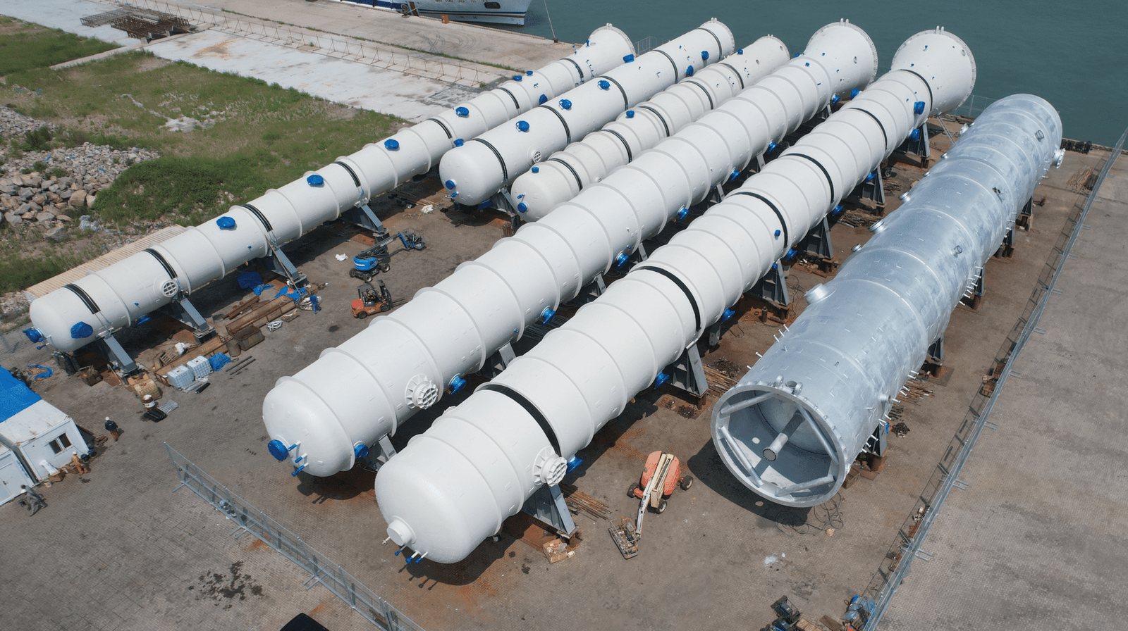
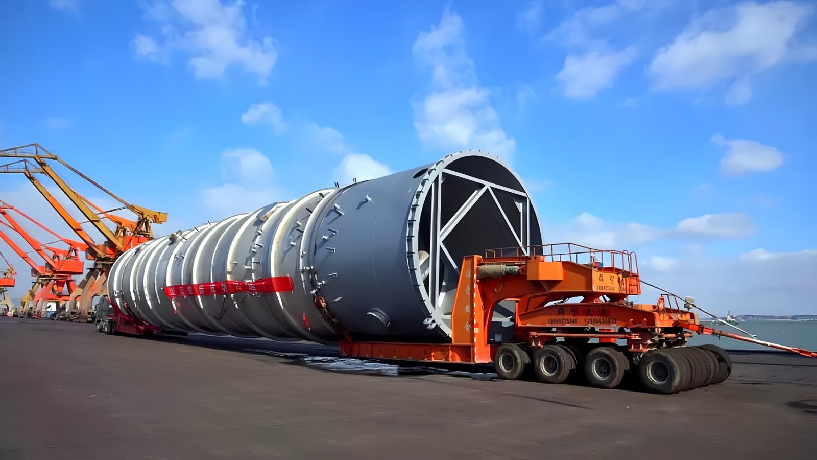
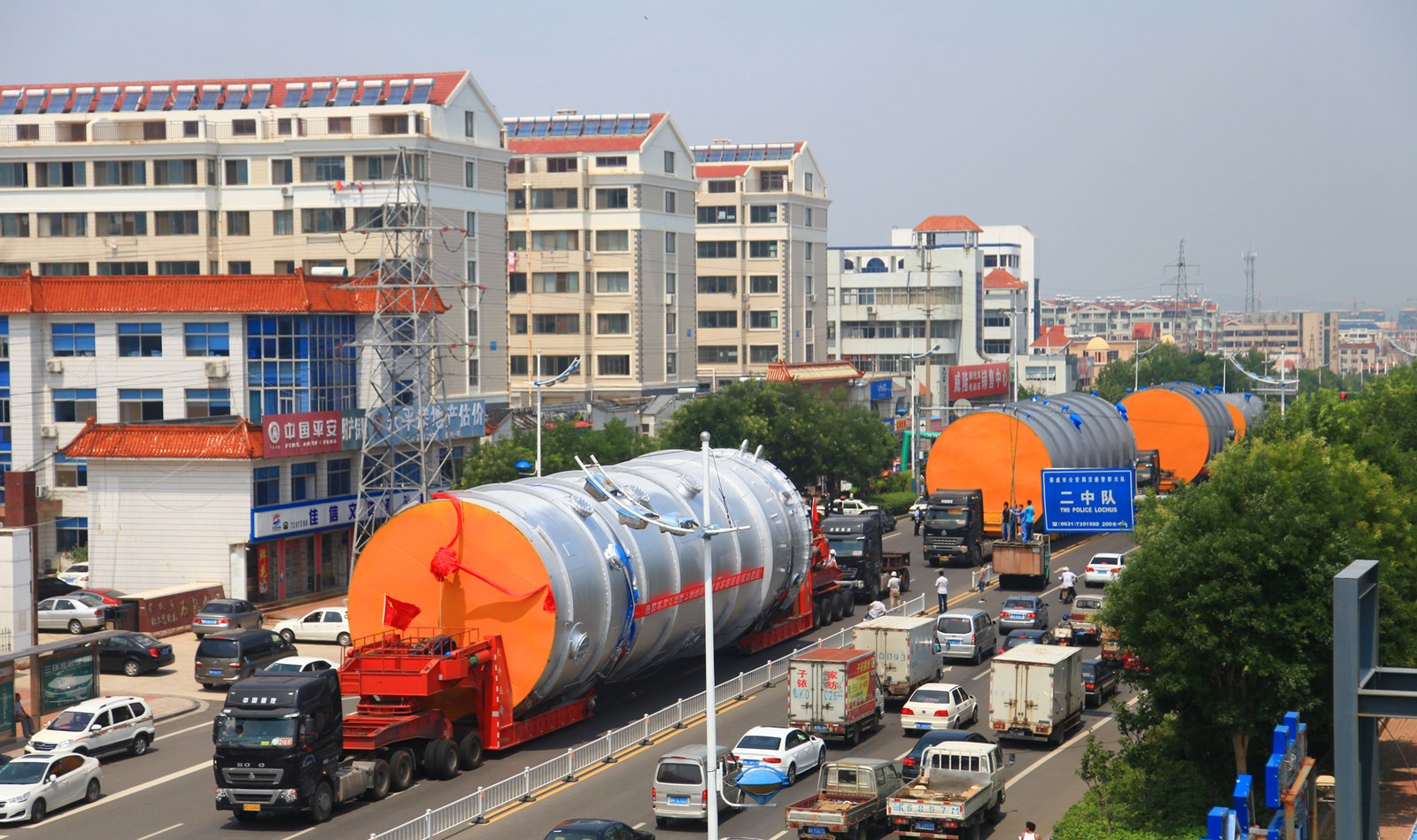
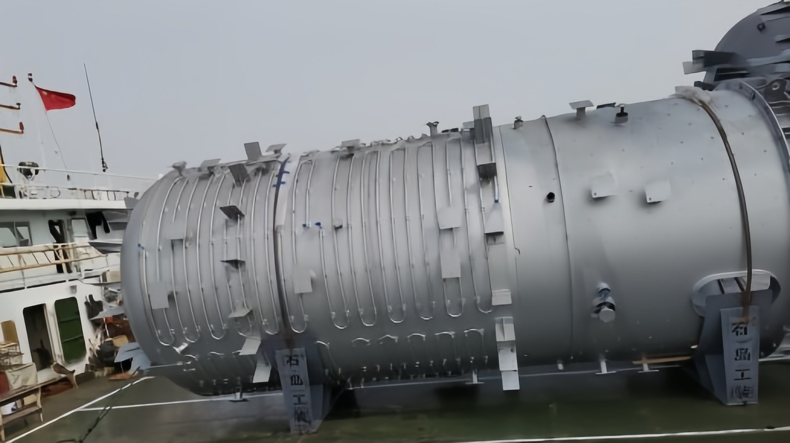
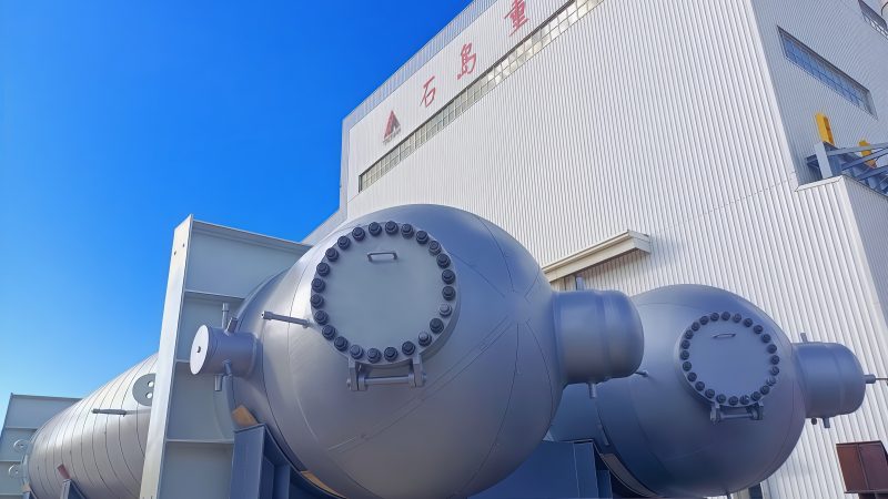
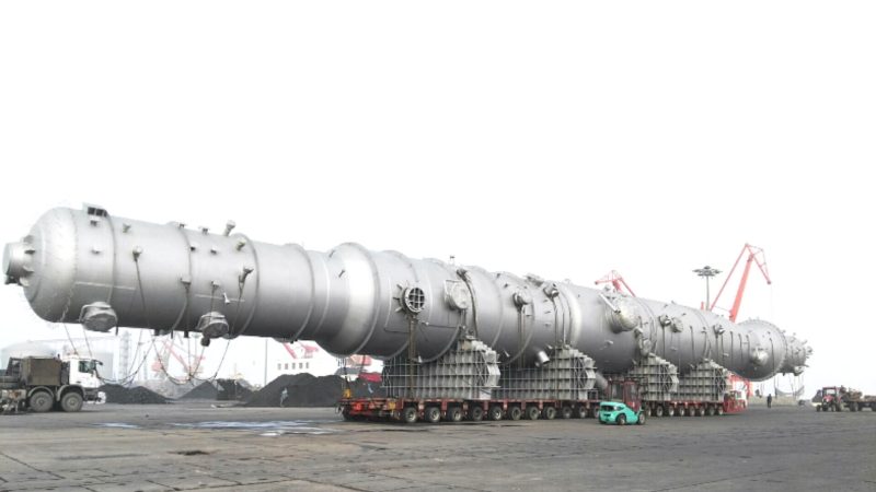
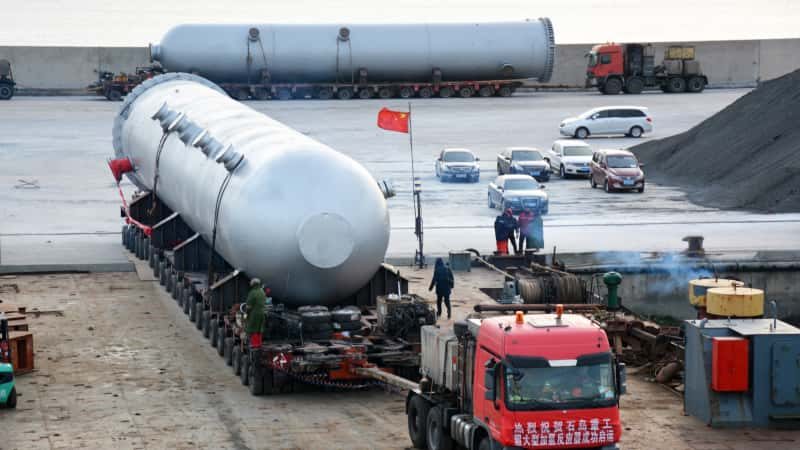
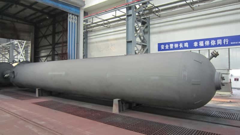
In the industrial production of ammonia, efficiency, safety, and yield are key concerns. Yet, many engineers and plant operators struggle to understand the inner workings of one of the most critical components: the ammonia synthesis tower. Misunderstandings or poor design choices can lead to reduced ammonia yields, higher energy consumption, and costly downtime. To optimize performance and ensure long-term reliability, it’s essential to understand what an ammonia synthesis tower is, how it operates, and what factors influence its effectiveness.
An ammonia synthesis tower is a high-pressure reactor used in the Haber-Bosch process to catalytically convert hydrogen and nitrogen gases into ammonia (NH₃) under specific conditions of temperature and pressure. It functions by compressing reactant gases and passing them over iron-based catalysts inside a vertical pressure vessel, where chemical equilibrium favors the formation of ammonia.
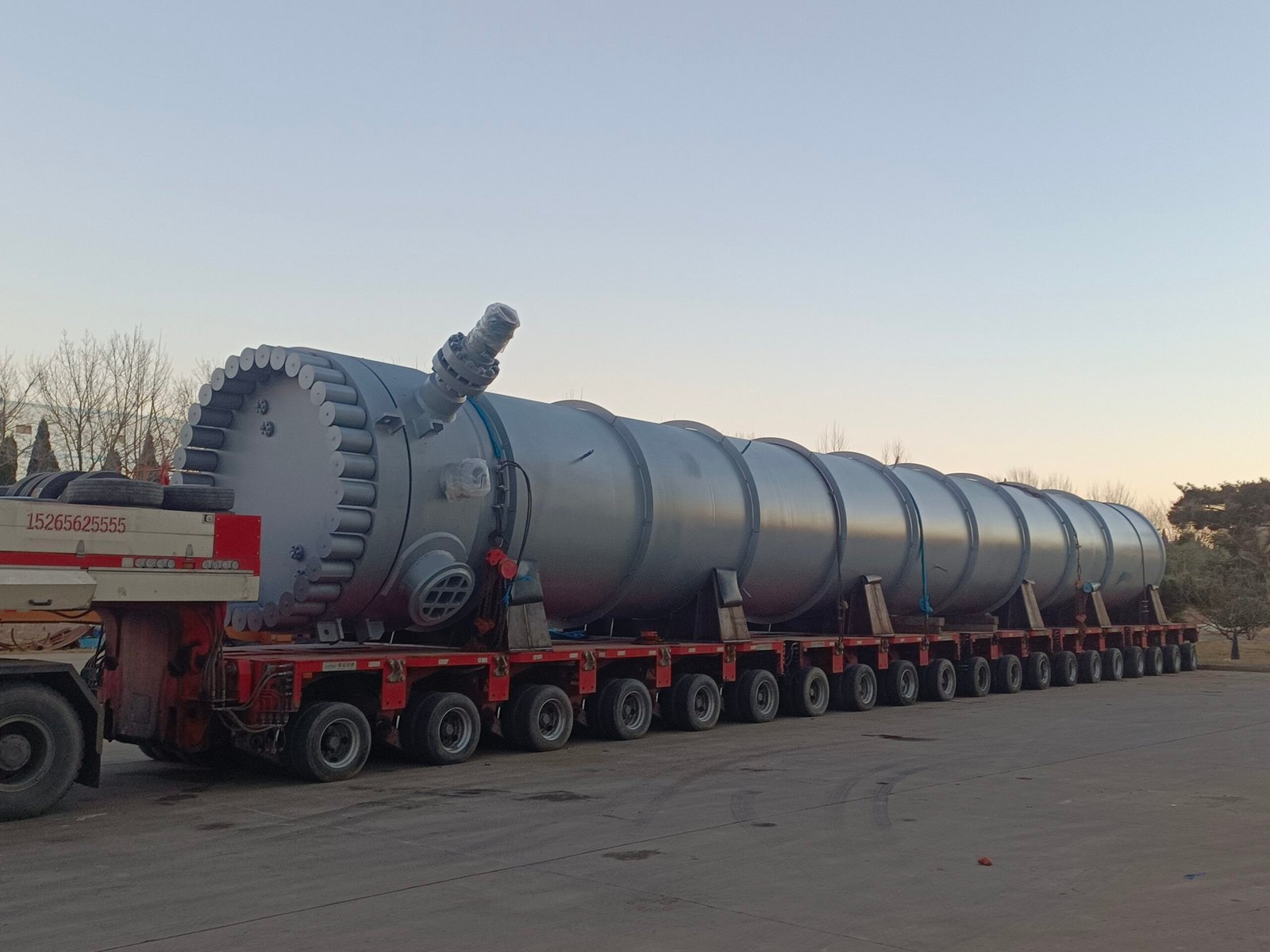
Understanding this process is key to optimizing ammonia production. In the rest of this article, we’ll explore how ammonia synthesis towers are designed, how they operate, and what technical considerations impact their efficiency and longevity.
What is the basic structure and function of an ammonia synthesis tower?
In modern chemical manufacturing, ammonia synthesis is a vital process—especially in the production of fertilizers. But one of the biggest pain points for engineers and operators is the complexity and maintenance demands of the ammonia synthesis tower, which is the heart of the Haber-Bosch process. Without a clear understanding of its internal structure and thermodynamic functions, operators risk suboptimal yields, costly shutdowns, or even dangerous pressure build-ups. Fortunately, with a proper breakdown of the tower’s structure and function, this highly pressurized, high-temperature chemical reactor can be safely and efficiently operated. This article will walk you through everything you need to know about the basic structure and function of an ammonia synthesis tower from a practical and engineering-focused perspective.
An ammonia synthesis tower is a high-pressure reactor where nitrogen (N₂) and hydrogen (H₂) gases react over an iron-based catalyst at high temperatures (400–500°C) and pressures (150–300 bar) to form ammonia (NH₃); the tower is structured with multiple catalyst beds, internal heat exchangers, and quench systems to optimize reaction equilibrium and thermal efficiency.
Understanding this fundamental structure is the first step in mastering the operation and optimization of ammonia synthesis units. If you’re involved in fertilizer production, hydrogen economy development, or large-scale chemical process engineering, you’ll find that a working knowledge of this reactor’s design is critical to ensuring high conversion rates and long-term plant reliability.
Ammonia synthesis towers always operate at atmospheric pressure.False
Ammonia synthesis requires high-pressure conditions (typically 150–300 bar) to shift the equilibrium toward ammonia production according to Le Chatelier’s Principle.
Catalyst beds inside ammonia synthesis towers must be periodically replaced.True
Catalyst beds lose activity over time due to sintering, poisoning, or fouling, requiring scheduled maintenance and replacement.
The ammonia synthesis reaction is exothermic.True
The reaction N₂ + 3H₂ ⇌ 2NH₃ releases heat, making it exothermic and requiring temperature management to avoid equilibrium inhibition.
Structure of an Ammonia Synthesis Tower
The ammonia synthesis tower (also called a synthesis converter) is a cylindrical pressure vessel typically constructed from high-strength alloy steel to withstand both the high pressure and temperature of the process. Below is a detailed overview of its main internal components:
| Component | Description | Function |
|---|---|---|
| Shell and Liner | Alloy steel outer shell with internal stainless steel or nickel lining | Withstands pressure, protects against hydrogen embrittlement |
| Catalyst Beds | Iron-based catalyst supported in porous trays or baskets | Promotes the reaction N₂ + 3H₂ ⇌ 2NH₃ |
| Heat Exchangers | Internal exchangers or feed/effluent heat exchangers | Recovers heat and preheats incoming gases |
| Quench Systems | Cold gas injection points between catalyst beds | Controls temperature and maximizes yield |
| Gas Distributor/Collector | Ensures even flow of gases across catalyst beds | Uniform flow distribution to avoid channeling and dead zones |
| Outlet Separator | At the top of the tower, where ammonia is condensed and separated | Removes NH₃ from unreacted N₂ and H₂, which are recycled |
Catalyst Bed Configuration (Typical 3-Bed Design):
| Bed Number | Purpose | Quench Between Beds? | Temperature Range (°C) |
|---|---|---|---|
| 1st Bed | Initial high-conversion pass | Yes | 400–500 |
| 2nd Bed | Intermediate conversion | Yes | 380–450 |
| 3rd Bed | Final polishing reaction | No | 350–420 |
Function of the Ammonia Synthesis Tower
At its core, the synthesis tower facilitates the reaction of nitrogen and hydrogen into ammonia under optimal thermodynamic and kinetic conditions. The ammonia synthesis reaction:
\text{N}_2 + 3\text{H}_2 \rightleftharpoons 2\text{NH}_3 + \text{Heat}
This reaction is:
- Exothermic (releases heat)
- Equilibrium-limited
- Favored by high pressure and low temperature (but not too low due to kinetics)
Functional Phases:
- Gas Pre-treatment: N₂ and H₂ are purified, dried, and mixed in a 1:3 molar ratio.
- Gas Pre-heating: Mixed gases are heated using the effluent from the tower.
- Catalytic Reaction: The gases pass through multiple catalyst beds, where ammonia is formed.
- Quenching: Cold gases are injected between beds to control temperature and prevent catalyst deactivation.
- Heat Recovery: Hot outlet gases are used to preheat incoming gases, improving energy efficiency.
- Ammonia Separation: Ammonia is condensed and removed; unreacted gases are recycled.
Technical Diagram: Flow Inside an Ammonia Synthesis Tower
| Step | Component Involved | Temperature (°C) | Pressure (bar) | Reaction Occurring |
|---|---|---|---|---|
| 1 | Inlet Gas Distributor | \~250 | 200–300 | None – only distribution |
| 2 | 1st Catalyst Bed | 400–500 | 200–300 | Fast forward reaction (high conversion) |
| 3 | Quench Zone 1 | Drops 20–40°C | Slight drop | Temperature moderation |
| 4 | 2nd Catalyst Bed | 380–450 | 190–280 | Further conversion |
| 5 | Quench Zone 2 | Drops 20–30°C | Slight drop | More temperature control |
| 6 | 3rd Catalyst Bed | 350–420 | 180–270 | Final conversion push |
| 7 | Ammonia Condenser | \~30 | 180–200 | NH₃ condensation and separation |
| 8 | Gas Recycle Loop | Ambient–200 | 180–300 | Unreacted gases returned |
Operational Considerations
Maintaining optimal temperature, pressure, and gas purity is essential. Major risks include:
- Catalyst poisoning (e.g., by sulfur or CO)
- Hydrogen embrittlement of reactor walls
- Thermal stress from rapid temperature changes
- Inefficient separation and recycle losses
To extend equipment life and optimize yield, advanced process control (APC), online gas chromatography, and predictive maintenance tools are often implemented.
Real-World Case: Yara Ammonia Plant Optimization
A study from Yara’s ammonia plant in Norway showed that by adjusting the quench flow between catalyst beds and increasing pressure slightly, they improved the NH₃ yield by 4.2% while reducing energy consumption by 2.5%. This case illustrates the massive impact of proper synthesis tower design and operation on both economics and sustainability.
Summary and Takeaway
The ammonia synthesis tower is not just a static vessel—it is an intricately engineered, thermodynamically optimized reactor core. Every internal component—from catalyst beds to quench zones—plays a role in driving the reaction forward efficiently. Mastery of this structure allows for increased ammonia production, reduced energy costs, and safer operation in chemical plants.
How Does the Ammonia Synthesis Tower Facilitate the Haber-Bosch Process?
Ammonia production is central to the global agricultural industry, yet the underlying chemical process—the Haber-Bosch method—is incredibly energy-intensive and equilibrium-limited. A critical challenge lies in enabling the nitrogen (N₂) and hydrogen (H₂) gases, both of which are inherently inert under normal conditions, to react efficiently. Without a proper reactor design, such as the ammonia synthesis tower, conversion rates would be uneconomically low. The synthesis tower plays a pivotal role by creating the precise environment—temperature, pressure, catalyst contact, and flow dynamics—needed to make the Haber-Bosch process industrially viable. This article will explore how the structure and operation of the ammonia synthesis tower is engineered specifically to overcome these challenges.
The ammonia synthesis tower facilitates the Haber-Bosch process by providing a high-pressure, high-temperature catalytic environment where nitrogen and hydrogen gases react to form ammonia; it optimizes conversion efficiency through multiple catalyst beds, interstage cooling (quenching), and heat recovery systems—all crucial to driving the exothermic, equilibrium-limited reaction forward.
This summary highlights why the synthesis tower is the linchpin of ammonia production. But to fully understand its contribution, one must delve deeper into its internal configuration, chemical engineering principles, and real-world performance metrics. Let’s continue.
The ammonia synthesis tower functions only as a storage tank.False
The tower is a high-pressure catalytic reactor, not a storage tank; it actively facilitates the Haber-Bosch reaction.
The Haber-Bosch process relies on an iron catalyst to enable ammonia synthesis.True
An iron-based catalyst is essential for promoting the reaction of nitrogen and hydrogen to form ammonia under industrial conditions.
High temperature alone is sufficient for high ammonia conversion.False
While high temperature increases reaction rate, excessive heat shifts equilibrium unfavorably for ammonia; optimal balance with high pressure is required.
The Core Chemistry of the Haber-Bosch Process
At the heart of the process is this reversible reaction:
\text{N}_2 (g) + 3\text{H}_2 (g) \rightleftharpoons 2\text{NH}_3 (g) + \text{Heat}
- Exothermic: Releases about −92 kJ/mol
- Dynamic Equilibrium: Forward rate vs. reverse rate determines yield
- Le Chatelier’s Principle: Reaction favors high pressure, lower temperatures
The synthesis tower is engineered to exploit these principles through a combination of pressure, heat, and catalyst surface area, making the reaction industrially feasible.
Internal Design Features That Enable the Haber-Bosch Process
| Feature | Description |
|---|---|
| High Pressure Containment | 150–300 bar to favor ammonia production via Le Chatelier’s principle |
| Iron Catalyst Beds | Activates nitrogen and promotes molecular collision with hydrogen |
| Multiple Reaction Stages | 2–4 catalyst beds with intermediate cooling to optimize conversion |
| Heat Recovery Units | Use hot product gas to preheat feed gas—enhancing energy efficiency |
| Quench Injection | Inter-stage cooling reduces temperature spikes and avoids equilibrium loss |
| Recycling Loop | Unconverted gases are separated and recirculated through the system |
Let’s examine each of these components in greater technical depth.
Catalyst Bed Configuration and Temperature Management
The exothermic nature of the reaction means heat builds up as the gas mixture moves through the catalyst. To manage this:
- First Bed: Receives the coldest gas and achieves the highest conversion rate.
- Intermediate Quench: Injects cold hydrogen/nitrogen gas to reduce temperature.
- Subsequent Beds: Smaller conversion, but still significant to push equilibrium.
| Catalyst Bed | Inlet Temp (°C) | Outlet Temp (°C) | Conversion Rate |
|---|---|---|---|
| 1st | 350–400 | 450–500 | 20–30% |
| 2nd | 370–400 | 450–480 | 10–15% |
| 3rd | 360–390 | 440–470 | 5–10% |
| Final Yield | – | – | 15–25% per pass |
Why not use a single bed? Because after a certain point, the forward rate slows and reverse reaction begins to dominate if the gas becomes too hot. Multi-bed systems with cooling help prevent this.
Schematic: Reaction Optimization Inside the Tower
| Step | Function | Engineering Role |
|---|---|---|
| 1 | Feed gas preheating | Uses hot effluent to preheat incoming gas |
| 2 | Entry to first catalyst bed | High initial reaction rate |
| 3 | Quenching | Lowers gas temp to reset for next reaction |
| 4 | Second/Third catalyst bed | Continues conversion |
| 5 | Ammonia condensation | Removes NH₃ from mixture |
| 6 | Gas recycling | Returns unconverted N₂ and H₂ |
Pressure and Its Importance
| Parameter | Value | Impact on Process |
|---|---|---|
| Reaction Pressure | 150–300 bar | Shifts equilibrium toward ammonia formation |
| Compressor Stage | Multi-stage, intercooled | Reduces power consumption and gas heating |
| Vessel Strength | Alloy steel, ASME Class | Ensures integrity under high pressure |
Note: Increasing pressure boosts ammonia yield but also raises operational cost due to compressor power demand and material stress.
Real-World Optimization Strategy: Pressure vs. Yield Curve
| Pressure (bar) | Temp (°C) | Ammonia Yield (%) |
|---|---|---|
| 100 | 450 | 10–12 |
| 200 | 450 | 18–22 |
| 300 | 450 | 26–30 |
This data, from BASF and KBR reactor designs, shows why synthesis towers typically operate in the 200–300 bar range: beyond that, the yield increase is marginal compared to cost.
Energy Efficiency and Heat Recovery
In the Haber-Bosch process, energy recovery is critical because:
- The process is endothermic on the front-end (gas production)
- Exothermic in the tower (synthesis reaction)
- Most energy lost as heat unless recovered
Key Strategies:
- Feed/effluent heat exchanger: Recovers \~80% of energy
- Waste heat boiler: Generates steam for use in compressors or elsewhere
- Condenser heat: Used to preheat boiler feed water
| Energy Unit | Purpose | Efficiency (%) |
|---|---|---|
| Feed Gas Preheater | Heat recovery from effluent | 80–85 |
| Waste Heat Boiler | Generates high-pressure steam | 70–75 |
| Steam Turbine Drive | Powers compressors (indirect) | 65–70 |
Automation and Control Systems
Modern synthesis towers use:
- DCS/PLC systems for automated pressure/temperature control
- Gas chromatographs to monitor N₂, H₂, NH₃ composition
- Real-time quench control to maintain optimal temperatures
- Catalyst health monitoring to determine fouling or deactivation trends
These technologies ensure stable yield, protect equipment, and reduce downtime.
Summary: Why the Tower is Crucial
Without the ammonia synthesis tower:
- The Haber-Bosch process would be thermodynamically inefficient
- Conversion rates would be too low for practical use
- Catalyst degradation and thermal loss would reduce profitability
With the tower:
- High-pressure, multi-stage catalytic conversion is feasible
- Reaction heat is harnessed and managed efficiently
- Unconverted gases are recovered and reused
This is why the ammonia synthesis tower remains the centerpiece of modern nitrogen-based fertilizer production.
What Are the Optimal Temperature and Pressure Conditions Inside an Ammonia Synthesis Tower?
One of the most critical aspects of operating an ammonia synthesis tower efficiently is maintaining the right temperature and pressure conditions. If the temperature is too high, the reaction equilibrium shifts away from ammonia formation. If it’s too low, the reaction rate plummets. Similarly, pressure must be sufficiently high to favor ammonia yield, but not so excessive that it causes material stress or skyrocketing energy costs. Many operators struggle to strike this delicate balance, leading to reduced output, high energy bills, or even catalyst degradation. Understanding the optimal range for temperature and pressure within the reactor is essential for maximizing conversion efficiency, plant uptime, and economic return.
The optimal operating temperature inside an ammonia synthesis tower is typically between 400°C and 500°C, while the optimal pressure ranges from 150 to 300 bar; these conditions are carefully selected to balance reaction kinetics with thermodynamic equilibrium, ensuring high conversion efficiency of nitrogen and hydrogen into ammonia without excessive energy consumption or catalyst degradation.
These values aren’t arbitrary—they’re the result of over a century of industrial process engineering and thermodynamic modeling. Maintaining this balance is key to sustaining the Haber-Bosch process on a continuous basis, especially in high-throughput ammonia plants. Below, we delve into the why and how of these values, with detailed technical backing and process diagrams.
Ammonia synthesis is more efficient at higher temperatures.False
Although higher temperatures increase reaction rate, they shift the equilibrium toward the reactants, reducing ammonia yield.
High pressure promotes ammonia formation in the Haber-Bosch process.True
According to Le Chatelier’s Principle, increased pressure favors the side of the reaction with fewer gas molecules—in this case, ammonia.
Operating above 600°C enhances catalyst performance in ammonia synthesis.False
Temperatures above 600°C can degrade the iron catalyst and reduce ammonia yield due to equilibrium limitations.
Thermodynamics and Kinetics: Why These Conditions?
The ammonia synthesis reaction is:
\text{N}_2 (g) + 3\text{H}_2 (g) \rightleftharpoons 2\text{NH}_3 (g) + \text{Heat}
- ΔH = −92.4 kJ/mol (exothermic)
- 4 moles of gas → 2 moles of gas (volume reduction)
Therefore:
- Lower temperatures increase yield but slow reaction.
- Higher pressures push the equilibrium toward ammonia.
- A catalyst is needed to activate N₂ and accelerate reaction rate.
Optimal Operating Conditions in Detail
| Parameter | Optimal Range | Why It’s Optimal |
|---|---|---|
| Temperature | 400–500°C | Ensures a balance between fast kinetics and acceptable yield |
| Pressure | 150–300 bar | Shifts equilibrium toward ammonia while keeping energy use in check |
| Catalyst Type | Iron-based (Fe, K₂O, Al₂O₃ promoters) | Durable, active at moderate T and P |
| Space Velocity | 3,000–10,000 h⁻¹ | Controls residence time for reactants |
Temperature vs Yield
| Temperature (°C) | Ammonia Yield per Pass (%) | Catalyst Life (years) | Reaction Rate |
|---|---|---|---|
| 350 | 30–35 | 10–12 | Very Low |
| 450 | 15–20 | 7–10 | High |
| 500 | 10–12 | 4–6 | Very High |
| 550+ | <10 | < 3 | Catalyst damage |
Pressure vs Yield
| Pressure (bar) | Ammonia Yield per Pass (%) | Energy Use (kWh/ton NH₃) | Equipment Cost |
|---|---|---|---|
| 100 | 8–10 | \~9,000 | Moderate |
| 150 | 12–15 | \~10,000 | High |
| 250 | 18–22 | \~11,000 | Very High |
| 300+ | 22–25 | \~12,500 | Extremely High |
Takeaway: The sweet spot for modern reactors is 150–250 bar and 400–500°C to strike an efficient balance between capital cost, operational energy, and yield.
Reactor Temperature Profile
A multi-bed catalyst configuration allows staged temperature control:
| Reactor Bed | Inlet Temp (°C) | Outlet Temp (°C) | Quench Required? |
|---|---|---|---|
| 1st Bed | 400 | 480–500 | Yes |
| 2nd Bed | 430 | 470–490 | Yes |
| 3rd Bed | 420 | 460–480 | No |
A quench gas is injected between beds to cool the reaction mixture. This maintains the reaction rate without overheating the catalyst and shifting equilibrium away from NH₃.
Process Flow and Optimization
| Stage | Description |
|---|---|
| Feed Gas Entry | Preheated via heat exchanger with outgoing product gas |
| 1st Catalyst Bed | Highest conversion due to fresh gas |
| Quench Injection | Lowers temperature \~30–40°C before next catalyst bed |
| 2nd Catalyst Bed | Further conversion with controlled exothermic heat |
| Effluent Cooling | Heat exchanged with incoming feed |
| NH₃ Condensation | Ammonia removed at \~30°C under pressure |
| Recycle Loop | Unreacted gases returned via compressor |
Advanced Control Systems for Optimal Conditions
Modern synthesis towers use:
- PID temperature control loops
- DCS automation with feedforward control
- Thermocouple arrays inside catalyst beds
- Pressure alarms and interlocks
- Catalyst bed differential pressure sensors
These tools allow fine-grained control of the ammonia reactor environment, ensuring optimal performance within the narrow window of ideal conditions.
Real-World Case Study: KBR Purifier™ Reactor
KBR’s Purifier™ synthesis loop operates at:
- Temperature: 450–480°C
- Pressure: 170–180 bar
- Per-pass yield: \~18%
- Total loop conversion: >98% after recycle
By using advanced internals like radial flow catalyst baskets and axial quenching, this reactor achieves extremely efficient operation while reducing power demands by \~5%.
Conclusion: The Critical Role of T and P
The ammonia synthesis tower is a finely tuned high-pressure reactor, and its success depends almost entirely on hitting the correct combination of temperature and pressure. Deviating from this operating window—even slightly—can result in reduced yield, increased energy costs, and shortened catalyst life. Mastering these conditions is not just a theoretical concern—it is the key to profitable, sustainable ammonia production.
What Role Do Catalysts Play in the Ammonia Synthesis Tower’s Operation?
The ammonia synthesis tower is the cornerstone of the Haber-Bosch process, enabling the conversion of nitrogen and hydrogen gases into ammonia under high pressure and temperature. However, despite extreme conditions, the natural chemical reaction between N₂ and H₂ is incredibly slow due to the stability of the nitrogen molecule. This bottleneck makes industrial-scale ammonia production impossible without intervention. The game-changer is the catalyst—a material that dramatically accelerates reaction rates without being consumed. Without catalysts, ammonia production would grind to a halt, even under ideal pressure and temperature. This article explores how catalysts function inside the synthesis tower, why iron remains the industry standard, and how emerging innovations are changing reactor efficiency.
Catalysts in the ammonia synthesis tower accelerate the reaction between nitrogen and hydrogen by lowering the activation energy required to break the strong triple bond in nitrogen (N₂); iron-based catalysts, promoted with potassium and alumina, provide active surface sites where adsorption, dissociation, and recombination of gas molecules occur, enabling continuous ammonia formation at industrially viable rates.
Catalysts are not optional in this process—they are essential. Their surface chemistry and thermal stability directly dictate the performance, efficiency, and cost-effectiveness of ammonia production. Let’s explore exactly how.
The nitrogen molecule (N₂) has a triple bond that is difficult to break.True
The N≡N triple bond has a bond energy of 941 kJ/mol, making it extremely stable and requiring catalytic activation for reaction.
Catalysts are consumed in the ammonia synthesis reaction.False
Catalysts facilitate the reaction but are not consumed; however, they may degrade over time due to sintering or poisoning.
Only platinum group metals can be used as ammonia synthesis catalysts.False
Iron is the most widely used and cost-effective catalyst in ammonia synthesis, not platinum group metals.
Why Catalysts Are Needed in the Haber-Bosch Process
The core reaction is:
\text{N}_2 + 3\text{H}_2 \leftrightarrow 2\text{NH}_3 + \text{Heat}
- Thermodynamics favor the forward reaction under high pressure.
- Kinetics, however, are extremely slow without a catalyst because:
- N₂ is inert due to its strong triple bond.
- H₂ requires dissociation before bonding with nitrogen.
Without a catalyst, the rate of ammonia formation is negligible, even at 500°C and 300 bar.
| Factor | Without Catalyst | With Catalyst |
|---|---|---|
| Activation Energy | >250 kJ/mol | 100–125 kJ/mol |
| Time to Equilibrium | Days to weeks | Seconds to minutes |
| Per-pass Yield | <0.1% | 15–25% |
| Industrial Feasibility | Impossible | Economically viable |
Catalyst Composition in the Synthesis Tower
The standard catalyst used in ammonia synthesis towers is based on magnetite (Fe₃O₄), which is reduced in-situ to metallic iron (Fe) under hydrogen at startup. It includes promoters that enhance performance.
| Component | Purpose |
|---|---|
| Iron (Fe) | Active catalyst surface |
| Potassium Oxide (K₂O) | Electronic promoter – enhances nitrogen adsorption |
| Aluminum Oxide (Al₂O₃) | Structural promoter – prevents sintering |
| Calcium Oxide (CaO) | Improves thermal stability |
| Silica (SiO₂) | Mechanical strength |
These components are mixed, pelletized, and activated before use.
Surface Chemistry: How Catalysis Works Inside the Reactor
Ammonia synthesis proceeds on the catalyst surface via multiple steps:
- Adsorption of N₂ and H₂ onto iron surface
- Dissociation of H₂ → H and N₂ → N atoms
- Surface migration of H and N atoms
- Association of N + 3H → NH₃ molecule
- Desorption of ammonia gas from surface
| Step | Reaction Phase | Energy Role |
|---|---|---|
| 1 | Physisorption | Weak van der Waals forces |
| 2 | Chemisorption | Breaks N≡N and H–H bonds |
| 3 | Surface mobility | Allows atoms to meet |
| 4 | Reaction | NH₃ formation |
| 5 | Desorption | Releases product |
The rate-limiting step is nitrogen dissociation, which is only feasible on highly active metal surfaces like reduced iron.
Catalyst Bed Configuration in the Tower
Modern ammonia towers use multiple catalyst beds, with inter-stage cooling (quenching). This design manages the exothermic nature of the reaction while maximizing conversion.
| Catalyst Bed | Temperature Range (°C) | Role in Reaction |
|---|---|---|
| First Bed | 400–500 | Highest activity, greatest conversion |
| Second Bed | 420–480 | Additional conversion, cooled gas |
| Third Bed | 420–470 | Final polishing of unreacted gases |
Note: Catalyst deactivation occurs if temperatures exceed 550°C or if impurities (e.g., sulfur, CO) are present.
Catalyst Performance Over Time
| Performance Metric | Initial Catalyst | After 3 Years | After 5+ Years |
|---|---|---|---|
| Surface Area (m²/g) | 100+ | 80–90 | <60 |
| NH₃ Yield per Pass (%) | 20–25 | 18–22 | 15–18 |
| Activity | 100% | 85–90% | 70–80% |
Common Deactivation Mechanisms:
- Sintering: Particle fusion reduces surface area.
- Poisoning: Sulfur, chlorine, or carbon monoxide block active sites.
- Abrasion: Loss of shape and integrity in fluidized systems.
Advanced Catalysts and Trends
Recent advancements are exploring:
| Catalyst Type | Advantages | Limitations |
|---|---|---|
| Ruthenium-based | High activity at lower pressures | Very expensive |
| Cobalt-molybdenum | Resistance to poisoning | Lower activity than iron |
| Barium-promoted Fe | Enhanced electron transfer for N₂ cleavage | Stability at high T questionable |
| Nanostructured Fe/Al₂O₃ | Higher surface area, faster kinetics | Production complexity |
Real-World Data: BASF and Topsoe Plants
| Plant Location | Catalyst Used | NH₃ Yield (%) | Catalyst Life (Years) | Pressure (bar) |
|---|---|---|---|---|
| BASF, Germany | Fe + K₂O/Al₂O₃ | 18–20 | 6–8 | 200–250 |
| Topsoe, Denmark | Advanced Fe matrix | 20–22 | 8–10 | 150–200 |
These performance numbers show the importance of high-quality catalyst manufacturing and protection systems.
Economic Impact of Catalyst Efficiency
| Metric | Without Catalyst | With Optimized Catalyst |
|---|---|---|
| Energy Required (kWh/ton NH₃) | >50,000 | 8,000–10,000 |
| Reactor Volume Needed (m³) | 5–10× larger | Compact |
| Annual Output (tons) | <100,000 | >1,000,000 |
| Downtime for Maintenance | Frequent | Minimal |
Catalyst selection directly affects the economic viability of ammonia plants.
Summary: The Catalyst’s Central Role
The ammonia synthesis tower cannot function without a catalyst. Iron-based catalysts serve as the reaction’s foundation, enabling high conversion rates and economic feasibility under extreme conditions. Their performance determines the tower’s temperature profile, energy efficiency, product yield, and maintenance schedule. Proper selection, protection, and regeneration of catalysts are therefore among the most critical factors in operating a world-class ammonia plant.
What Are the Common Challenges in Ammonia Synthesis Tower Operation and How Can They Be Resolved?
Operating an ammonia synthesis tower, the heart of the Haber-Bosch process, is a feat of precision engineering. But even the best-designed systems are vulnerable to numerous challenges—ranging from catalyst degradation and heat management issues to pressure fluctuations and contamination. These problems not only reduce production efficiency but also increase operational costs and the risk of unplanned shutdowns. Many plants experience severe productivity losses due to undiagnosed mechanical or chemical faults in the tower. Fortunately, with a clear understanding of these challenges and their proven solutions, operators can maintain optimal performance and extend equipment life.
Common challenges in ammonia synthesis tower operation include catalyst deactivation, heat exchanger fouling, pressure drop across catalyst beds, gas contamination, and improper temperature control; these can be resolved by regular catalyst monitoring and replacement, quench zone optimization, use of high-efficiency feed gas purification systems, advanced process control (APC), and predictive maintenance strategies.
Addressing these issues requires more than just technical knowledge—it demands a holistic strategy that spans design, operation, monitoring, and preventive maintenance. In the sections below, we provide in-depth insights into each challenge and offer actionable solutions based on industrial best practices.
Catalyst beds in ammonia synthesis towers require no maintenance during their lifespan.False
Catalyst beds degrade over time due to sintering, fouling, and poisoning; periodic inspection and replacement are required.
Fluctuations in temperature within the reactor can negatively affect ammonia yield.True
Unstable temperatures can shift reaction equilibrium and deactivate the catalyst, leading to lower ammonia production.
Feed gas purity does not affect the operation of the ammonia synthesis tower.False
Impurities such as sulfur, chlorine, and CO can poison the catalyst and severely impact reaction efficiency.
1. Catalyst Deactivation
Catalyst life is directly tied to tower performance. Over time, even the most robust iron-based catalysts lose activity due to:
| Cause | Description | Effect on Tower |
|---|---|---|
| Sintering | High temperatures cause particles to fuse | Reduced surface area |
| Poisoning | Sulfur, CO, and chlorine bind to active sites | Complete deactivation in areas |
| Fouling | Dust or impurities block pores | Lower reaction rates |
| Mechanical Breakdown | Vibration or abrasion causes pellet disintegration | Uneven flow, bed collapse |
Solutions:
- Use feed gas purifiers (ZnO beds, guard beds).
- Schedule catalyst performance audits every 12–18 months.
- Install multi-layer catalyst grading (inert + guard + active).
- Rotate in fresh catalyst or regenerate used catalyst off-site.
| Catalyst Lifespan Scenario | Catalyst Life (Years) | Notes |
|---|---|---|
| Ideal Operations | 8–10 | With clean gas and stable operation |
| Moderate Contamination | 5–7 | Partial fouling |
| Severe Poisoning | < 3 | Emergency shutdown likely |
2. Temperature Control Issues
Ammonia formation is highly temperature-sensitive. Excessive heat can reduce yield, while low temperatures stall the reaction.
| Problem Type | Cause | Consequence |
|---|---|---|
| Overheating | Poor quenching or excessive gas compression | Catalyst sintering, yield drop |
| Cold zones | Inadequate preheat or exchanger fouling | Incomplete reaction |
| Temperature spike | Quench system failure | Pressure surges, thermal shock |
Solutions:
- Use multi-point temperature sensors inside catalyst beds.
- Calibrate quench gas injection regularly.
- Employ Advanced Process Control (APC) to maintain setpoint.
Recommended Quenching Protocol:
| Catalyst Bed | Inlet Temp (°C) | Quench Gas Flow | Temp Drop (°C) |
|---|---|---|---|
| 1st to 2nd | 480 → 430 | 3–5% feed gas | \~50 |
| 2nd to 3rd | 460 → 420 | 2–3% feed gas | \~40 |
3. Pressure Drop Across Catalyst Beds
Excessive pressure drop is a sign of internal flow resistance—often due to mechanical issues or fouling.
| Source of Pressure Drop | Indicator | Resolution |
|---|---|---|
| Dust accumulation | Gradual increase over months | Replace or clean guard bed |
| Collapsed catalyst bed | Sudden spike in dP readings | Shut down and inspect internals |
| Clogged gas distributor | Uneven flow temperatures | Clean internals, replace trays |
| Optimal ΔP Range | Typical Value | Maximum Allowable |
|---|---|---|
| Catalyst Section | 0.3–0.5 bar | 1.0 bar |
Solutions:
- Install differential pressure transmitters per bed.
- Implement regular gas flow mapping using tracer studies.
- Use layered catalysts with particle size grading to reduce compaction.
4. Contaminants in Feed Gas
Impurities in N₂ and H₂ feed gases can irreversibly poison catalysts and lead to long-term yield losses.
| Common Contaminant | Source | Impact |
|---|---|---|
| Sulfur (H₂S, COS) | Natural gas, process leaks | Strong poisoning, catalyst death |
| CO/CO₂ | Reforming stage | Slows reaction, carbon fouling |
| Chlorides | Cooling water leaks | Corrosion, catalyst poisoning |
| Water/Oil vapor | Compressor carryover | Steam formation, channeling |
Solutions:
- Install guard beds with ZnO, CuO, and molecular sieves.
- Maintain compressor oil seals and heat exchanger integrity.
- Use online gas chromatographs for purity verification.
5. Mechanical Failures
Internal mechanical components (trays, baskets, thermocouples) can degrade due to thermal cycling and vibration.
| Component Affected | Failure Mode | Symptom |
|---|---|---|
| Tray support beams | Creep, corrosion | Catalyst shifting, bed collapse |
| Thermocouples | Burnout | No temp feedback, runaway heating |
| Quench nozzle | Plugging, misalignment | Poor cooling, temp rise |
| Catalyst baskets | Warping | Uneven flow, catalyst escape |
Solutions:
- Schedule internal inspections during annual turnarounds.
- Use alloy steels and ceramic components for high durability.
- Adopt Finite Element Analysis (FEA) during design to identify stress zones.
6. Poor Gas Flow Distribution
Uneven flow can cause:
- Hot spots
- Catalyst bypassing
- Dead zones
| Cause | Solution |
|---|---|
| Poor distributor design | Use CFD modeling for redesign |
| Catalyst settling | Use multi-sized grading |
| Blocked flow channels | Regular cleanout and distribution tuning |
CFD Simulation Example:
A plant in Southeast Asia found that retrofitting a radial gas distributor improved NH₃ yield by 4% and extended catalyst life by 2 years.
Summary Table of Challenges and Resolutions
| Challenge | Detection Method | Solution Strategy |
|---|---|---|
| Catalyst Deactivation | Activity testing, GC | Regeneration, grading, pure feed gas |
| Temperature Control Issues | Thermocouple arrays | APC tuning, quench optimization |
| Pressure Drop | Differential P sensors | Guard beds, flow mapping, filter cleaning |
| Contamination | Gas chromatography | Purifiers, leak sealing, separator checks |
| Mechanical Failures | Visual inspection, NDT | Alloy upgrades, robust design |
| Flow Distribution Problems | CFD + thermography | Flow redistributor, basket redesign |
Real-World Case Study: Yara’s Reactor Retrofit
Problem: Frequent temperature spikes and yield loss at Yara’s ammonia plant in the Netherlands
Diagnosis: Improper quench gas distribution + fouled catalyst
Action: Redesigned quench nozzles, added ZnO guard bed, installed smart thermocouples
Result:
- NH₃ yield increased by 5.8%
- Catalyst life extended by 3 years
- Downtime reduced by 70%
Final Thoughts
Ammonia synthesis tower operation is a balance of precision, chemistry, and mechanical integrity. While challenges are inevitable due to the process’s extreme conditions, they can be proactively managed with the right technologies and preventive strategies. Whether you’re facing performance degradation, frequent maintenance issues, or low conversion rates, the solutions often lie in better catalyst handling, gas purification, thermal management, and flow engineering.
How Can Ammonia Synthesis Tower Efficiency Be Improved Through Modern Engineering Advancements?
Despite over a century of operation, ammonia synthesis via the Haber-Bosch process remains energy-intensive and complex. Traditional towers operate under extreme pressure (150–300 bar) and temperature (400–500°C), consuming 1–2% of global energy. With rising energy costs, stricter emission goals, and growing fertilizer demand, inefficiencies in synthesis towers can no longer be tolerated. Legacy designs are limited by equilibrium constraints, thermal losses, and outdated process controls. However, modern engineering advancements now offer powerful solutions—from AI-assisted automation to nanostructured catalysts—that significantly boost performance, cut emissions, and reduce downtime. This article explores the technologies that are transforming ammonia reactor efficiency today.
Ammonia synthesis tower efficiency can be significantly improved through modern engineering advancements such as high-activity nanocatalysts, dynamic quench control systems, process intensification (e.g., modular reactors and membrane integration), advanced process control (APC), real-time analytics, and AI-driven optimization; these innovations increase conversion rates, lower energy consumption, reduce maintenance, and enable flexible, low-carbon operation.
These breakthroughs allow older plants to be retrofitted for higher throughput, and new plants to be built smaller, cleaner, and smarter. Let’s examine each innovation and how it integrates into the reactor operation.
Modern engineering advancements can reduce energy consumption in ammonia synthesis.True
Technologies like advanced catalysts, heat recovery, and AI-driven controls significantly reduce the energy input required for ammonia production.
Ammonia synthesis tower design has remained unchanged since the 1900s.False
While the basic chemistry is the same, reactor internals, catalysts, control systems, and integration with digital technologies have evolved dramatically.
Using AI and sensors in ammonia plants can improve yield and safety.True
AI and sensor-based systems provide real-time insights that optimize temperature, pressure, and catalyst performance, enhancing both efficiency and safety.
1. High-Performance Catalysts: Nanotechnology and Beyond
The foundation of efficiency improvement is the catalyst. Traditional iron-based systems are robust but limited in activity and temperature range.
| Catalyst Type | Advantages | Limitation |
|---|---|---|
| Nanostructured Fe | High surface area, faster kinetics | Sensitive to sintering |
| Ruthenium-based | Active at lower pressure and temperature | Expensive, sensitive to poisoning |
| Cobalt/Molybdenum | Sulfur-resistant, low pressure capable | Lower conversion at high rates |
| Layered Double Hydroxides (LDH) | High dispersion, tunable properties | Under development |
Impact on Reactor Efficiency:
| Catalyst Upgrade | Ammonia Yield Increase (%) | Energy Savings (%) | Catalyst Life (Years) |
|---|---|---|---|
| Standard Fe | Baseline | Baseline | 6–8 |
| Nano-Fe/Al₂O₃ | +5–8 | −8–12 | 5–6 |
| Ru-based on carbon | +10–15 | −15–20 | 3–5 |
These materials can reduce required operating pressure from 250 to 150 bar while maintaining similar yields.
2. Advanced Heat Integration and Recovery Systems
Heat losses account for 30–40% of energy waste in ammonia synthesis. Improved heat exchanger design, including plate-fin exchangers, counterflow systems, and waste heat boilers, are transforming thermal efficiency.
| Heat Recovery Unit | Function | Efficiency Gain |
|---|---|---|
| Feed/effluent exchanger | Preheats reactants using hot outlet gas | +15–20% |
| Waste heat boiler (WHB) | Generates steam from reactor effluent | +10–15% |
| Condenser heat integration | Reuses cooling energy | +5–7% |
Case Study: Johnson Matthey’s heat integration in European plant
- Resulted in 8% fuel gas savings
- Steam generation increased by 12%
- ROI in less than 24 months
3. Quench Zone Optimization with Intelligent Injection
In multi-bed towers, temperature control is managed through quenching—injecting cold gas between catalyst beds.
Old Approach:
- Fixed-rate quenching
- Manual adjustments
Modern Approach:
- Real-time feedback loop with thermocouples
- Smart valve control for responsive gas injection
- AI-model prediction to prevent overheating
| Benefit | Description |
|---|---|
| Prevents catalyst sintering | Keeps bed temp under 500°C |
| Increases conversion | Maintains temperature near optimal 450°C |
| Improves safety | Avoids thermal runaway and pressure spikes |
4. Process Intensification via Modular and Membrane Reactors
Process intensification means packing more reaction into less space with less energy.
Key Technologies:
- Membrane Reactors: Separate ammonia as it forms → shifts equilibrium → more yield
- Modular Microreactors: Compact units with high surface-to-volume ratio
- Loop Redesign: Removing mechanical compressors with chemical looping
| Reactor Type | Yield Increase (%) | Footprint Reduction | Energy Savings |
|---|---|---|---|
| Membrane-integrated | +20–30 | 20–40% | 15–20% |
| Modular skid-based | +10–15 | 50% | 10–15% |
5. AI, Digital Twin & Real-Time Process Control
Industry 4.0 tools are transforming ammonia plants into smart systems.
| Technology | Function | Impact on Efficiency |
|---|---|---|
| Digital Twin | Simulates reactor behavior under any condition | Prevents downtime, optimizes start-up |
| Predictive Analytics | Forecasts catalyst fouling, heat loss trends | Enables preemptive maintenance |
| AI-Based APC | Optimizes quench, pressure, feed gas ratios | +5–10% yield improvement |
| Smart Sensors | Continuous monitoring of T/P/flow | Enhances safety and stability |
Data Dashboard Example:
| Parameter | Live Value | AI-Optimized Range | Alert Threshold |
|---|---|---|---|
| Reactor Temp (°C) | 472 | 450–480 | >490 |
| Bed Pressure (bar) | 245 | 240–260 | >270 |
| NH₃ Yield (%) | 21.4 | >20.5 | <19.0 |
6. Decarbonization Integration
Modern engineering also focuses on sustainable ammonia production.
| Innovation | Environmental Impact | Efficiency Benefit |
|---|---|---|
| Green H₂ (via electrolysis) | Reduces CO₂ emissions from SMR reforming | Cleaner feedstock |
| Heat pump recovery | Uses low-grade waste heat | Reduces fuel gas usage |
| CO₂ capture & reuse | Prevents venting from front-end process | Enables urea production |
Plants combining electrification + green hydrogen + smart synthesis towers are already achieving 90%+ decarbonization targets.
Comparative Table: Traditional vs. Modern Ammonia Tower
| Feature | Traditional Tower | Modernized Tower |
|---|---|---|
| Catalyst | Fe-based | Nano-Fe / Ru-based / dual-layer |
| Pressure | 250–300 bar | 150–200 bar |
| Temperature | 450–500°C | 400–480°C |
| Control System | Manual or PID | AI-assisted APC + Digital Twin |
| Heat Recovery | Partial | Fully integrated + WHB |
| Yield per Pass | 15–18% | 20–25% |
| CO₂ Emissions | High | Low to near-zero |
| Downtime | Moderate to frequent | Predictive-based minimal |
Ending Thoughts
Ammonia synthesis tower efficiency is no longer limited by traditional engineering boundaries. With modern catalysts, intelligent process control, heat recovery systems, and digital transformation, even old plants can achieve next-generation performance. These innovations don’t just cut costs—they extend catalyst life, reduce environmental impact, and allow for flexible operation under varying feedstock or market conditions. The integration of AI and smart sensors means your reactor learns and improves continuously—marking a new era in ammonia manufacturing.
Conclusion
Understanding the ammonia synthesis tower’s structure and function is essential for anyone involved in chemical plant design, maintenance, or optimization. With proper knowledge, you can ensure higher yield, lower operational costs, and safer plant operation.
If you’re seeking professional guidance or equipment solutions for ammonia synthesis towers, contact us today for expert support and tailored recommendations.
FAQ
1.What is the main function of an ammonia synthesis tower?
A1:
An ammonia synthesis tower, also known as an ammonia converter, is designed to facilitate the chemical reaction between nitrogen (N₂) and hydrogen (H₂) gases under high pressure and temperature to produce ammonia (NH₃). This process is central to the Haber-Bosch method of ammonia production. The tower provides the necessary environment for the catalyst to initiate and sustain the reaction, maintaining optimal pressure, temperature, and gas flow for efficient conversion.
2.How is an ammonia synthesis tower structured?
A2:
The ammonia synthesis tower is typically a vertical cylindrical vessel made from high-strength alloy steel. Internally, it houses multiple catalyst beds, heat exchangers, and insulation layers. The gases flow through the catalyst beds, where the reaction occurs. Heat exchangers are used to recover and redistribute heat within the system to maintain the necessary reaction temperatures. The structural design ensures optimal contact time between reactants and catalyst while minimizing pressure drops and maximizing conversion rates.
3.Why are high pressure and temperature necessary in ammonia synthesis?
A3:
Ammonia synthesis is an exothermic reaction that favors high pressure to shift the chemical equilibrium toward ammonia production. High temperatures (typically around 400–500°C) are required to increase the reaction rate, although too high a temperature can reduce yield due to equilibrium limitations. A pressure of 150–300 atmospheres is common, as it promotes the forward reaction and increases overall production efficiency within the tower.
4.What type of catalyst is used in an ammonia synthesis tower?
A4:
The most commonly used catalyst in ammonia synthesis towers is iron-based with promoters like potassium and aluminum oxides. These catalysts enhance the rate of reaction by lowering the activation energy, allowing the nitrogen and hydrogen gases to combine more readily. Catalysts are arranged in multiple beds within the tower to ensure efficient conversion and thermal management across stages of the reaction.
5.How does gas flow through the ammonia synthesis tower?
A5:
Gas flow in an ammonia synthesis tower typically follows a countercurrent or radial flow pattern, depending on the tower design. The hydrogen and nitrogen mixture enters the reactor and passes through preheating and heat exchange systems before reaching the catalyst beds. As the reaction occurs and heat is generated, internal heat exchangers help maintain consistent temperatures. Unreacted gases are often recycled back through the system to improve efficiency.
References
Ammonia Production – Wikipedia
https://en.wikipedia.org/wiki/Ammonia_production
Source: WikipediaHaber Process – Royal Society of Chemistry
https://edu.rsc.org/resources/haber-process/4010182.article
Source: Royal Society of ChemistryAmmonia Synthesis – ScienceDirect
https://www.sciencedirect.com/topics/chemical-engineering/ammonia-synthesis
Source: ScienceDirectCatalysts in the Haber Process – Compound Interest
https://www.compoundchem.com/2014/09/03/haberprocess/
Source: Compound InterestAmmonia Synthesis Loop – Haldor Topsoe
https://www.topsoe.com/processes/ammonia/ammonia-synthesis-loop
Source: Haldor TopsoeDesign of Ammonia Reactors – Engineering Toolbox
https://www.engineeringtoolbox.com/ammonia-reactor-design-d_1996.html
Source: Engineering ToolboxHow Ammonia is Made – The Chemical Engineer
https://www.thechemicalengineer.com/features/how-ammonia-is-made/
Source: The Chemical EngineerAmmonia Plant Safety and Operation – AIChE
https://www.aiche.org/resources/publications/cep/2019/september/ammonia-plant-safety-and-operation
Source: AIChEAmmonia Synthesis Catalysts – Johnson Matthey
https://matthey.com/products-and-markets/chemicals/ammonia-synthesis-catalysts
Source: Johnson MattheyProcess Engineering in Ammonia Synthesis – Elsevier
https://www.elsevier.com/books/process-engineering-in-ammonia-synthesis/prausnitz/978-0-444-42882-4
Source: Elsevier


