In many critical industrial processes—such as in petrochemical, oil & gas, and power generation—selecting the wrong heat exchanger can lead to system inefficiencies, increased operational costs, or even equipment failure. Hairpin heat exchangers, known for their compact design and high thermal efficiency, are often ideal for demanding applications. However, choosing the right hairpin heat exchanger for your specific use case requires careful evaluation of several factors. Failing to do so can result in underperformance or costly retrofits. This article helps you navigate the key considerations to make the right selection confidently.
The right hairpin heat exchanger is chosen based on factors such as process fluid properties, pressure and temperature requirements, thermal duty, fouling tendencies, material compatibility, and maintenance accessibility. Matching exchanger design to these operational parameters ensures optimal heat transfer, operational safety, and long-term reliability in your specific application.

Choosing the right hairpin heat exchanger isn’t a one-size-fits-all decision. Read on to understand which variables matter most, how to match exchanger types with your system needs, and what to ask your supplier before finalizing your purchase.
What Are the Key Design Considerations When Selecting a Hairpin Heat Exchanger?
In high-efficiency thermal systems, especially where compactness and versatility are required, improper selection of heat exchangers can lead to underperformance, higher maintenance, and system inefficiency. One commonly used option in process industries is the hairpin heat exchanger, valued for its modularity, thermal effectiveness, and adaptability to both phase-change and non-phase-change duties. However, choosing the wrong configuration or sizing can lead to pressure losses, fouling issues, and increased operational costs. This article explores the critical design factors that must be considered when selecting a hairpin heat exchanger to ensure long-term performance, reliability, and cost-effectiveness.
The key design considerations when selecting a hairpin heat exchanger include thermal duty, pressure drop limits, fluid properties, fouling tendencies, phase change behavior, material compatibility, cleaning and maintenance needs, and space constraints. Additionally, choices between single- or double-pipe construction, number of hairpins, and use of longitudinal baffles or double tubesheets depend heavily on the specific process requirements.
Understanding the specifics of your application—fluid characteristics, required heat transfer rate, and pressure constraints—is essential. This helps determine whether a hairpin configuration is appropriate compared to shell-and-tube or plate exchangers. Let’s dive deeper into these core parameters that directly affect the selection and design of a hairpin heat exchanger.
Hairpin heat exchangers are ideal for applications with large temperature cross and limited space.True
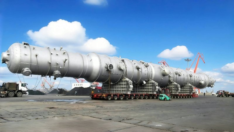
Hairpin heat exchangers are compact and offer high heat recovery efficiency, especially in applications involving phase change or high temperature differentials.
Thermal Duty and Heat Transfer Requirements
![]()
Hairpin exchangers are particularly well-suited to duties where:
- One fluid is undergoing phase change (e.g., condensing steam).
- There is a large temperature cross (i.e., the outlet temperature of one stream is higher than the inlet of the other).
- A counter-current flow design maximizes LMTD.
| Fluid Type | Typical U-Value (W/m²·K) | Suitability for Hairpin Design |
|---|---|---|
| Steam Condensation | 2500–10000 | Excellent |
| Oil–Water | 100–300 | Good |
| Gas–Gas | 10–100 | Moderate (requires larger area) |
Pressure Drop Considerations
Hairpin heat exchangers allow for customizable pressure drop control because the flow is divided across multiple tubes. The pressure drop must be evaluated for both the shell and tube sides to avoid excessive pumping requirements.
Factors affecting pressure drop:
- Tube length and diameter
- Fluid velocity
- Fouling factor
- Presence of flow-enhancing devices (e.g., inserts or turbulators)
Pressure drop constraints often determine:
- Number of hairpin modules
- Pass arrangements (1-pass, 2-pass)
- Tube diameter
| Design Variable | Effect on Pressure Drop |
|---|---|
| Smaller Tube Diameter | Increases pressure drop |
| More Hairpin Sections | Reduces per-tube velocity, lowers drop |
| Increased Tube Length | Increases drop due to friction |
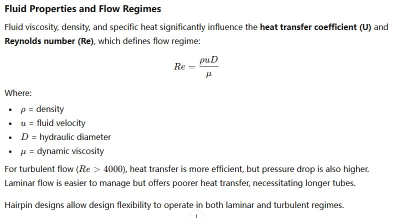
Fluid Properties and Flow Regimes
Phase Change and Two-Phase Flow
Hairpin heat exchangers are often selected for condensation or boiling duties, such as:
- Steam condensers in power and chemical plants
- Evaporators in refrigeration
- Reboilers for distillation columns
When phase change is involved:
- Tube orientation (horizontal vs. vertical) affects performance.
- Proper drainage is crucial in condensers.
- Flow distribution must avoid maldistribution and slugging.
| Phase Change Application | Hairpin Suitability | Notes |
|---|---|---|
| Condensation (Steam) | High | Compact and efficient; avoids subcooling |
| Evaporation (Refrigerants) | Moderate to High | Requires careful control of dry-out |
| Flash Cooling | High | Maximizes temperature difference |
Fouling, Maintenance, and Cleanability
Fouling can drastically reduce exchanger performance. Hairpin exchangers offer advantages in cleanability, particularly if removable bundles or straight tubes are used.
Common fouling factors:
- Scaling (e.g., from hard water)
- Biological fouling (e.g., algae, biofilm)
- Chemical deposition (e.g., polymerization)
To manage fouling:
- Use fouling-resistant materials
- Design for ease of disassembly
- Incorporate cleaning ports or CIP systems
| Cleaning Option | Suitable Hairpin Feature |
|---|---|
| Mechanical rod cleaning | Straight tube hairpin |
| Chemical cleaning (CIP) | Detachable bundle design |
| Pigging system | Dual-pipe removable bundle |
Hairpin heat exchangers are harder to clean than shell-and-tube types.False
Hairpin heat exchangers can be designed with removable bundles and straight tubes, allowing easier mechanical or chemical cleaning compared to large shell-and-tube exchangers.
Materials and Corrosion Resistance
Material selection must consider:
- Process fluid compatibility
- Operating temperature and pressure
- Corrosion or erosion risks
Common materials used:
- Carbon steel (for oil/gas, low corrosion)
- Stainless steel (food, pharma, corrosive chemicals)
- Duplex or Hastelloy (chlorides, high temp)
Material choice affects cost, lifespan, and regulatory compliance (e.g., ASME codes).
| Material | Corrosion Resistance | Cost | Common Applications |
|---|---|---|---|
| Carbon Steel | Low | Low | Hydrocarbons, low-corrosion fluids |
| Stainless Steel | High | Medium | Food, beverage, chemicals |
| Hastelloy C-276 | Very High | High | Chlorides, acids |
Compactness and Space Constraints
Hairpin exchangers are particularly suited for applications with limited plot space due to their compact footprint and modular design. Vertical or horizontal mounting options provide flexibility in:
- Offshore platforms
- Skid-mounted systems
- Retrofits in confined spaces
In contrast to large horizontal shell-and-tube designs, hairpin exchangers require less shell diameter for the same surface area by extending in length rather than width.
| Comparison | Shell & Tube Exchanger | Hairpin Exchanger |
|---|---|---|
| Footprint | Large (horizontal area) | Compact (elongated) |
| Modularity | Fixed | Easy to scale (add hairpins) |
| Orientation | Usually horizontal | Horizontal or vertical |
Common Configurations and When to Use Them
| Configuration | Best For | Notes |
|---|---|---|
| Single Tube Hairpin | Low-flow, high-temp duties | Simplest, easiest to clean |
| Double Pipe with Annulus | Steam condensers, oil coolers | Compact, good for phase change |
| Finned Tube Hairpin | Air-side cooling/heating | Enhanced heat transfer on gas side |
| Multi-Hairpin Parallel | High-duty, low pressure drop systems | Distributes flow across multiple units |
| Longitudinal Fin Hairpin | Viscous fluids | Compensates for poor convection |
Case Study: Hairpin Heat Exchanger in Steam Condensing Application
Industry: Petrochemical
Fluid: High-pressure steam
Thermal Duty: 2.5 MW
Temperature Cross: 180°C steam in → 70°C condensate out; 30°C process water in → 90°C out
Chosen Design: Dual hairpin with double-pipe configuration, stainless steel
Performance: Achieved 92% heat recovery, reduced plot space by 40% vs. shell-and-tube
In summary, the selection of a hairpin heat exchanger involves a balanced understanding of thermal performance, mechanical limitations, material durability, and operational considerations. By addressing each design factor—heat duty, flow regime, fouling, pressure drop, and spatial constraints—you can ensure a reliable and efficient exchanger tailored to your specific process conditions.
How Do Fluid Properties Impact the Selection of a Hairpin Heat Exchanger?
When engineers overlook fluid properties during heat exchanger design, they risk oversized equipment, inefficient heat transfer, increased pressure drops, and even equipment failure due to corrosion or fouling. In systems using hairpin heat exchangers, fluid characteristics are especially critical, because these exchangers are often deployed for challenging heat transfer scenarios such as large temperature crosses, high-viscosity fluids, or phase-change operations. To avoid costly mistakes and maximize performance, it’s essential to understand how fluid properties directly influence the sizing, materials, configuration, and maintenance of hairpin heat exchangers.
Fluid properties such as viscosity, thermal conductivity, density, specific heat, fouling tendency, and corrosiveness significantly influence the selection and design of a hairpin heat exchanger. These properties determine the heat transfer coefficient, pressure drop, flow regime (laminar or turbulent), and material compatibility—all of which impact exchanger size, layout, and performance efficiency.
Choosing a hairpin heat exchanger without considering these fluid properties can lead to poor thermal performance and increased operational costs. Understanding these parameters allows for a tailored solution that ensures both optimal heat transfer and mechanical integrity.
Fluid viscosity has minimal impact on heat exchanger performance.False
Fluid viscosity greatly affects heat transfer efficiency and pressure drop, especially in laminar flow regimes, making it a critical design factor.
The Core Fluid Properties That Influence Hairpin Heat Exchanger Design
Hairpin heat exchangers rely on precise thermal and hydraulic calculations. These calculations are governed by the following key fluid properties:
| Property | Impact on Heat Exchanger Selection |
|---|---|
| Viscosity (μ) | Affects pressure drop and flow regime; high μ → laminar flow |
| Thermal Conductivity (k) | Higher k improves heat transfer rate |
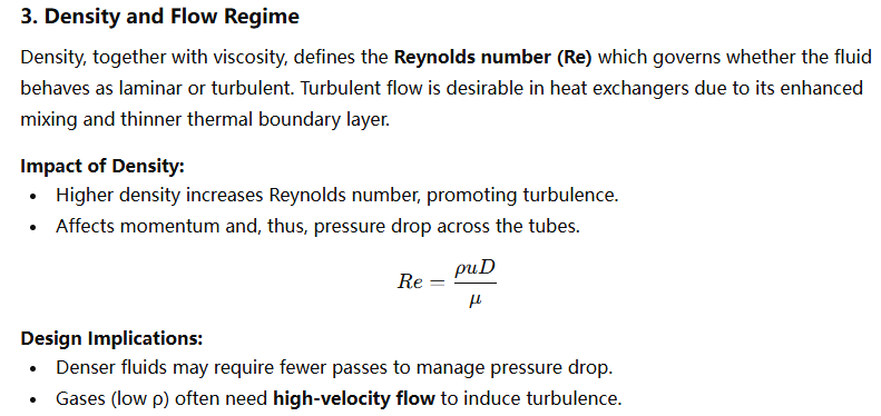
| Density (ρ) | Impacts Reynolds number and pressure drop |
| Specific Heat (Cp) | Affects required surface area to meet duty |
| Fouling Tendency | Influences need for cleaning and fouling factors |
| Corrosiveness | Dictates material selection and service life |
Below, we explore each in detail and how it directly affects design decisions.
1. Viscosity: The Flow Controller
Viscosity is one of the most influential fluid properties in determining the thermal and hydraulic performance of a hairpin heat exchanger. Fluids with high viscosity (e.g., heavy oils, polymers) typically exhibit laminar flow (Re < 2300), resulting in lower heat transfer coefficients.
Impact of Viscosity:
- Increases pressure drop: Higher viscous drag in narrow tubes.
- Reduces convective heat transfer: Laminar flows form thick boundary layers.
- Requires larger surface area: To compensate for lower heat transfer coefficient.
Design Solutions:
- Increase tube diameter (reduces velocity, lowers friction).
- Add internal turbulators to promote turbulence.
- Use finned tubes to enhance area for poor heat conductors.
| Fluid | Viscosity @ 40°C (cP) | Recommended Design Strategy |
|---|---|---|
| Water | 1 | Standard hairpin configuration |
| Crude Oil | 20–1000 | Large diameter tubes, longer length |
| Glycerin | 1000+ | Finned tubes, low-velocity design |
2. Thermal Conductivity: Driving Heat Transfer
Thermal conductivity defines how well a fluid can transfer heat through conduction. Low-k fluids (e.g., oils, gases) are poor heat conductors and require enhanced design to achieve target heat transfer.
Impact of Thermal Conductivity:
- Directly affects the overall heat transfer coefficient (U).
- Low k results in increased thermal resistance on the fluid side.
Design Solutions:
- Use counter-current flow to maximize LMTD.
- Add extended surface area (fins) inside or outside tubes.
- Increase turbulence to minimize boundary layer thickness.
| Fluid | Thermal Conductivity (W/m·K) | Heat Transfer Implication |
|---|---|---|
| Water | 0.6 | Excellent transfer, small area needed |
| Air | 0.025 | Poor conductor, needs enhanced surfaces |
| Oil | 0.1–0.2 | Requires larger surface or turbulence |
3. Density and Flow Regime
| Fluid | Density (kg/m³) | Recommended Approach |
|---|---|---|
| Steam | 0.6–3 | Small tubes, high velocity |
| Water | 1000 | Standard configuration |
| Ethylene Glycol | 1100 | Larger diameter or parallel pass design |
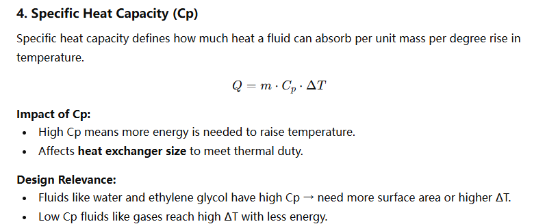
4. Specific Heat Capacity (Cp)
| Fluid | Specific Heat (kJ/kg·K) | Implication for Hairpin Design |
|---|---|---|
| Water | 4.18 | Efficient heat transfer, compact unit |
| Oil | 1.8–2.5 | Requires higher surface area |
| Air | 1.0 | Low energy storage, steep temp rise |
5. Fouling Characteristics
Fouling reduces effective heat transfer by introducing a thermal resistance layer on heat transfer surfaces.
Causes:
- Precipitation of salts (scaling)
- Biological growth (biofouling)
- Polymerization (chemical fouling)
Design Considerations:
- Use fouling factors in calculations (e.g., 0.0005–0.002 m²·K/W)
- Ensure easy cleaning access (removable bundles, straight tubes)
- Opt for anti-fouling materials or coatings
| Application | Fouling Risk | Mitigation Strategy |
|---|---|---|
| Wastewater Heating | High | Regular cleaning ports, stainless tubes |
| Clean Steam Heating | Low | Standard design |
| Crude Oil Processing | Very High | Low velocity, removable U-bundle configuration |
Fouling is typically not a concern in hairpin heat exchanger applications.False
Fouling can be significant depending on the process fluid and must be accounted for in both thermal design and maintenance planning.
6. Corrosiveness and Material Compatibility
Chemical compatibility between fluids and construction materials is critical for long-term durability and safety.
Common Corrosive Fluids:
- Chlorinated hydrocarbons
- Acids and alkalis
- Saltwater/brine
Design Actions:
- Select corrosion-resistant alloys: e.g., Hastelloy, Monel, Duplex stainless
- Use cladded tubesheets or double tubesheets to isolate fluids
- Apply internal coatings (e.g., PTFE-lined pipes)
| Fluid | Risk Level | Recommended Material |
|---|---|---|
| Seawater | High | Duplex SS, Titanium |
| Sulfuric Acid | High | Tantalum or PTFE-lined carbon steel |
| Organic Solvents (nonpolar) | Moderate | 316L SS or Alloy 20 |
Fluid Property Summary Table
| Property | Affects | Design Outcome |
|---|---|---|
| Viscosity | Re, Pressure Drop | Tube sizing, velocity control |
| Thermal Conductivity | U-value | Heat transfer efficiency |
| Density | Re, Pressure Drop | Flow regime, pressure losses |
| Specific Heat | Q, ∆T required | Area sizing, LMTD optimization |
| Fouling Tendency | U-value degradation | Cleaning provisions, tube access |
| Corrosiveness | Material longevity | Alloy selection, protection design |
Summy
Fluid properties are not just data points—they are foundational to every heat exchanger decision. In the case of hairpin heat exchangers, which are often applied in compact, high-efficiency systems, fluid characteristics determine not only sizing but also performance, longevity, and cost. From selecting the correct materials to determining tube configuration and flow velocity, each fluid attribute plays a role in the successful implementation of your exchanger.
💡 When designing or specifying a hairpin heat exchanger, always consult fluid property tables or conduct lab analysis to get accurate, temperature-dependent data. This ensures your design is precise and reliable.
Why Are Operating Pressure and Temperature Crucial in Choosing the Right Hairpin Heat Exchanger?
When engineers neglect to account for operating pressure and temperature during heat exchanger design, it can lead to catastrophic failures, system downtime, material degradation, and even safety hazards. This is particularly critical in high-pressure and high-temperature applications common in refineries, power plants, and chemical processing. Hairpin heat exchangers, known for their versatility and compact footprint, are often selected in such demanding conditions. However, unless these operating parameters are precisely defined and accommodated, the exchanger may suffer from mechanical failure, poor performance, or non-compliance with pressure vessel codes.
Operating pressure and temperature are crucial in selecting a hairpin heat exchanger because they directly influence the mechanical design, material selection, pressure vessel code compliance, safety margins, and thermal efficiency of the system. These parameters determine the exchanger’s ability to withstand internal stresses, avoid corrosion or creep, and deliver reliable long-term performance under harsh conditions.
Choosing a hairpin heat exchanger without considering its pressure and temperature limits can result in underspecified equipment, rapid degradation, or code violations. Let’s explore exactly why these parameters matter and how they shape every aspect of exchanger selection.
Hairpin heat exchangers are suitable only for low-pressure, low-temperature applications.False
Hairpin heat exchangers are designed for a wide range of pressures and temperatures and are commonly used in high-pressure and high-temperature industrial services.
The Core Role of Operating Pressure and Temperature in Hairpin Heat Exchanger Selection
Hairpin heat exchangers are pressure vessels and heat transfer units simultaneously. Their design must withstand both mechanical stress from pressure and thermal stress from temperature gradients. These stresses affect:
- Wall thickness and geometry
- Gasket and sealing methods
- Thermal expansion handling
- Choice of materials
- Welding methods and inspections
Below is a summary table illustrating how each parameter impacts design:
| Parameter | Design Impact |
|---|---|
| Operating Pressure | Determines wall thickness, tube layout, flanges |
| Operating Temperature | Affects material selection, thermal expansion, creep limits |
| Differential Pressure | Affects tubesheet and baffle design |
| Cyclic Temperature Variation | Requires stress-relieving design and flexible supports |
1. Pressure Ratings: Holding the System Together
Operating pressure defines the internal mechanical stress a hairpin heat exchanger must withstand. Pressures can vary from atmospheric (1 bar) to over 200 bar (2900 psi) in petrochemical and power applications.
Key Effects of High Pressure:
- Requires thicker walls and higher-grade materials to avoid rupture.
- Demands robust tube-to-tubesheet welds or double tubesheet designs.
- Influences flange rating and bolt sizing.
- Increases the likelihood of vibration and flow-induced fatigue.
Pressure Design Code Reference:
Most hairpin exchangers are designed to ASME Boiler and Pressure Vessel Code Section VIII, which sets:
- Minimum wall thickness formulas
- Hydrostatic test pressures
- Allowable stress limits
| Design Pressure (bar) | Typical Application | Wall Thickness Design Action |
|---|---|---|
| 10–20 | HVAC, food processing | Standard carbon steel or SS |
| 50–100 | Oil refineries | Thick-wall stainless or alloy tubes |
| 150–250+ | Hydrogen service, steam cracking | Exotic alloys, cladded shells |
Example:
For 100 bar pressure, a hairpin exchanger may need 10–12 mm shell wall thickness, with 3–4 mm tube wall thickness, depending on tube diameter and material.
2. Temperature Ratings: Controlling Material Behavior and Expansion
Operating temperature influences material strength, thermal expansion, and corrosion behavior. High temperatures can:
- Reduce the mechanical strength of metals.
- Cause creep deformation (slow elongation under load).
- Accelerate oxidation or corrosion.
- Create thermal stress differentials between shell and tube sides.
Typical Temperature Ranges:
- Low Temp: -50°C to 100°C (e.g., chilled water, glycol)
- Medium Temp: 100°C to 300°C (e.g., steam, condensate)
- High Temp: 300°C to 600°C (e.g., thermal oils, reboilers)
- Ultra-High Temp: >600°C (e.g., waste heat recovery)
| Temperature Range | Material Consideration | Design Action |
|---|---|---|
| -50°C to 150°C | Standard carbon steel, SS | Normal thermal expansion gaps |
| 150°C to 400°C | 304/316 SS, Duplex | Expansion joints, stress-relieving welds |
| 400°C to 600°C | Incoloy, Hastelloy | Creep-resistant design, cladded shells |
| >600°C | Chrome-moly steels, refractory linings | Highly engineered metallurgy, insulation |
3. Thermal and Mechanical Stress Interactions
Operating at high pressure and temperature simultaneously subjects the exchanger to compound stresses, especially at:
- Tube-to-tubesheet joints
- U-bends or return bends
- Welds and flanges
This interaction can lead to:
- Stress corrosion cracking (SCC)
- Creep-fatigue damage
- Thermal bowing or warping
Design Mitigation Strategies:
- Use expansion joints in shell or tubes.
- Apply finite element analysis (FEA) for critical zones.
- Choose materials with high creep rupture strength (e.g., Inconel 625).
- Control startup/shutdown ramp rates.
| Stress Type | Caused By | Impact Zone |
|---|---|---|
| Thermal Stress | Uneven expansion across materials | Tubesheet, bends |
| Pressure Stress | Internal pressure load | Shell, tubes, flanges |
| Creep | Sustained high temp + pressure | Tube walls, weld zones |
| Vibration | Flow-induced under pressure | Baffles, supports, tube banks |
Thermal stress has negligible impact on high-temperature hairpin exchangers.False
Thermal stress can cause tube expansion, cracking, and joint failures if not properly accounted for in high-temperature applications.
4. Material Selection Based on Pressure-Temperature Ratings
Materials must retain strength and resist corrosion under operating conditions. ASME and EN codes provide allowable stress values at different temperatures for each material.
Example: 316L Stainless Steel
- Safe up to ~500°C for pressure vessel use
- Good for most chemical services
- Creep risk increases above 550°C
Material Compatibility Table:
| Material | Max Temp (°C) | Max Pressure (bar) | Corrosion Resistance | Application Example |
|---|---|---|---|---|
| Carbon Steel | 400 | 50–100 | Low | Steam condensers |
| 304 SS | 500 | 100–150 | Moderate | Reboilers, water heaters |
| Duplex SS | 600 | 150–200 | High | Brine, offshore oil & gas |
| Incoloy 825 | 750 | 200+ | Very High | Acidic, high-temp services |
5. Code Compliance and Testing
Every exchanger operating above certain pressure and temperature thresholds must comply with local and international pressure vessel codes.
Design Standards to Follow:
- ASME Section VIII Div 1 & 2
- TEMA (Tubular Exchanger Manufacturers Association)
- EN 13445 (Europe)
- PED (Pressure Equipment Directive)
Key Tests Required:
- Hydrostatic pressure test (typically 1.3–1.5x design pressure)
- Radiographic inspection of critical welds
- Post-weld heat treatment (PWHT) for stress relief
| Test Type | Purpose | When Required |
|---|---|---|
| Hydrostatic Test | Validate pressure containment | All pressure vessels |
| Dye Penetrant/Magnetic Particle | Detect surface cracks | Welded zones |
| Radiography/Ultrasonic Test | Internal flaw detection | High-pressure critical welds |
6. Real Case Study: High-Temperature, High-Pressure Hairpin Exchanger
Application: Reboiler for refinery stripper column
Operating Conditions: 380°C, 130 bar
Fluid: Naphtha
Chosen Design:
- Material: Incoloy 800H tubes and shell
- Configuration: Double-pipe hairpin, U-bend design
- Special Features: Expansion joint in shell, cladded tubesheets
Result: - Zero failure incidents in 6 years
- Efficiency > 91%
- Annual maintenance reduced by 35%
Operating pressure and temperature are not secondary considerations—they are foundational design parameters for any hairpin heat exchanger. They dictate everything from wall thickness to metallurgy, from joint types to testing protocols. Whether you’re working with high-pressure hydrogen, superheated steam, or corrosive thermal oils, your exchanger must be built to withstand both the internal load and the heat—safely, efficiently, and reliably.
How Does Fouling Affect the Choice of Hairpin Heat Exchanger Design?
Fouling—whether from scaling, sludge, biofilm, or chemical deposits—is a silent efficiency killer in thermal systems. Left unchecked, it increases pressure drop, reduces heat transfer efficiency, and accelerates corrosion, ultimately driving up energy consumption and operational costs. In processes where hairpin heat exchangers are used—often involving viscous fluids, multi-phase flows, or aggressive chemicals—designing with fouling in mind is not optional, it’s essential. Failure to address fouling risks during the design stage can lead to frequent maintenance shutdowns, underperformance, and even complete exchanger failure.
Fouling directly impacts the choice of hairpin heat exchanger design by influencing tube geometry, material selection, maintenance access, flow configuration, and allowable fouling factors in thermal calculations. To ensure long-term reliability and efficiency, hairpin exchangers must be specifically designed to mitigate fouling, allow for easy cleaning, and tolerate performance degradation over time.
Understanding the type, severity, and frequency of fouling expected in your application is the first step in selecting the right hairpin heat exchanger configuration. This article breaks down the types of fouling, their design implications, and engineering strategies to control and combat them.
Fouling primarily affects heat transfer efficiency but has little impact on pressure drop.False
Fouling significantly increases pressure drop by reducing flow area and increasing surface roughness, which raises pumping energy requirements.
What Is Fouling and Why It Matters in Hairpin Heat Exchanger Design
Fouling refers to the accumulation of unwanted materials on the internal surfaces of a heat exchanger. These deposits act as thermal resistors and flow restrictors, leading to:
- Reduced heat transfer efficiency (lower U-value)
- Increased pressure drop across tubes
- Risk of hot spots and thermal stress
- Higher operating costs and energy consumption
- More frequent cleaning and downtime
There are five main types of fouling relevant to hairpin heat exchangers:
| Type of Fouling | Description | Common Sources |
|---|---|---|
| Scaling | Crystallization of dissolved minerals | Hard water, brine, calcium carbonate |
| Particulate | Deposition of suspended solids | Sludge, clay, rust particles |
| Biological | Growth of algae, bacteria, biofilm | Cooling water systems, wastewater treatment |
| Chemical (Corrosion) | Reaction products forming deposits | Corrosive chemicals, acidic media |
| Polymeric/Organic | Polymerized hydrocarbons or tars | Oil, bitumen, organic solvents |
How Fouling Affects Hairpin Heat Exchanger Design Parameters
Fouling imposes both thermal and hydraulic penalties. Engineers must incorporate fouling resistance (Rf) into the heat transfer calculations, which inflates the required surface area and influences the following parameters:
| Design Parameter | Fouling Impact |
|---|---|
| Tube Diameter | Larger diameters reduce clogging risk |
| Tube Length | Longer tubes may promote self-cleaning flow |
| Surface Finish | Smoother tubes resist fouling |
| Material Selection | Non-stick, corrosion-resistant alloys help |
| Removability | Straight or U-tube bundles for easy access |
| Cleaning Access | Flanged connections, clean-out ports |
Example of Fouling Factor (Resistance):
| Application | Fouling Factor (m²·K/W) |
|---|---|
| Clean Water | 0.0001–0.0002 |
| Cooling Tower Water | 0.0003–0.0009 |
| Crude Oil | 0.001–0.002 |
| Wastewater Effluent | 0.002–0.005 |
These values significantly increase required heat transfer surface area if not managed properly.
Design Strategies to Minimize Fouling in Hairpin Heat Exchangers
To mitigate fouling, hairpin heat exchangers can be engineered with multiple design strategies, each tailored to the type and severity of fouling expected.
1. Tube Geometry and Diameter Selection
- Larger diameters (e.g., 1.5″ to 2.5″) reduce the risk of clogging, especially for particulate fouling.
- Straight tubes make mechanical cleaning with rods or brushes easier.
- U-tube configurations may be less favorable where access is restricted.
| Tube Design | Fouling Suitability | Cleanability |
|---|---|---|
| 3/4″ U-bend | Prone to blockages | Moderate |
| 1.5″ Straight | Good for fouling fluids | Excellent |
| Corrugated Tube | Increases turbulence, anti-foul | Harder to clean |
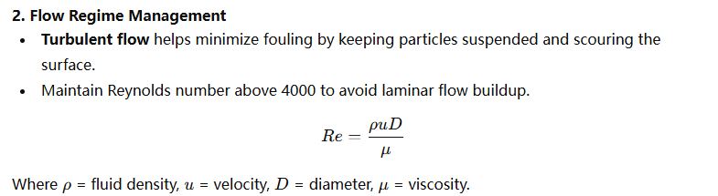
2. Flow Regime Management
| Flow Regime | Re Number | Fouling Behavior |
|---|---|---|
| Laminar | <2300 | High fouling risk |
| Transitional | 2300–4000 | Moderate fouling |
| Turbulent | >4000 | Self-cleaning effect |
3. Material and Surface Treatment
Choosing the right tube material helps resist corrosion-based fouling and enables high-temperature cleaning.
| Material | Corrosion Resistance | Fouling Resistance | Applications |
|---|---|---|---|
| Carbon Steel | Low | Moderate | Non-corrosive fluids |
| 316L Stainless | High | Good | Food, pharmaceuticals |
| Titanium | Very High | Excellent | Seawater, brine |
| Hastelloy C-276 | Extreme | Excellent | Acids, chlorides, slurry |
4. Cleanability and Maintenance Access
Hairpin exchangers offer modularity that simplifies fouling maintenance:
- Removable tube bundles allow offline cleaning or replacement.
- Mechanical cleaning via pigging or rod cleaning is ideal with straight tubes.
- Chemical cleaning (CIP) requires corrosion-resistant materials and tight sealing.
| Cleaning Method | Suitability for Hairpin Design |
|---|---|
| Rod Brushing | Straight-tube hairpin |
| High-pressure Jetting | Open-access flanged heads |
| CIP with Acid/Base | Resistant alloy tubes |
Real-World Case Study: Fouling-Optimized Hairpin Exchanger
Industry: Wastewater Bioreactor Heat Recovery
Fluids: Sludge and warm recycled effluent
Problem: Frequent fouling of shell-and-tube unit causing 40% efficiency loss every 3 months
Solution:
- Switched to double-pipe hairpin design with 2″ straight 316L tubes
- Implemented mechanical brushing every 6 months
- Included flanged closures for full bundle access
Result: - Thermal efficiency drop <5% over 6 months
- Maintenance reduced from quarterly to biannually
- ROI achieved in 14 months
Engineering Tools: Fouling Factor vs. Surface Area
Chart: Increase in Required Surface Area Due to Fouling Factor
| Fouling Factor (m²·K/W) | % Increase in Surface Area |
|---|---|
| 0.0002 | +5% |
| 0.0005 | +12% |
| 0.001 | +20% |
| 0.002 | +38% |
Source: Based on TEMA B class design for water-to-oil exchanger at 300 kW duty.
Fouling is not just a maintenance concern—it is a primary design criterion in hairpin heat exchanger selection. From determining tube diameter and flow velocity to choosing cleaning mechanisms and materials, fouling considerations shape the entire architecture of the exchanger. A proactive approach to fouling—grounded in fluid analysis, fouling factor estimation, and cleanable design—can save hundreds of hours in maintenance and thousands in operational costs annually.
💡 Always evaluate the fouling characteristics of your process fluid during the design phase. Ignoring them will cost you more later in downtime, inefficiency, and repairs.
Fouling is an afterthought in heat exchanger design.False
Fouling is a primary factor in heat exchanger design that impacts thermal sizing, material choice, cleaning provisions, and life-cycle cost.
What Material Selection Factors Influence Hairpin Heat Exchanger Performance and Lifespan?
Choosing the wrong material for a hairpin heat exchanger can lead to premature corrosion, thermal fatigue, fouling issues, or even catastrophic failure. In applications where the exchanger is exposed to aggressive fluids, high temperatures, and fluctuating pressures, material selection becomes one of the most critical decisions—directly affecting heat transfer efficiency, mechanical integrity, and total lifespan. If overlooked or improperly specified, material failure can lead to unscheduled shutdowns, costly replacements, and safety hazards. Selecting the right material ensures performance longevity, minimizes maintenance, and reduces total cost of ownership.
Material selection for hairpin heat exchangers is influenced by fluid corrosivity, operating temperature and pressure, mechanical strength requirements, thermal conductivity, fouling tendencies, industry standards, and lifecycle cost. The chosen material must be chemically compatible with both process and utility fluids, mechanically resilient under thermal and pressure stress, and maintain heat transfer performance over time.
To achieve optimal results, engineers must consider both the working environment and fluid properties when specifying materials for the tubes, shell, tubesheets, and other components of a hairpin heat exchanger. Let’s explore how these factors determine performance and durability.
Hairpin heat exchangers require the same materials regardless of operating fluid or conditions.False
Material selection must match the chemical compatibility, temperature, and pressure of the working fluids to ensure performance and avoid premature failure.
Key Material Selection Factors for Hairpin Heat Exchangers
Hairpin heat exchangers often operate in demanding environments such as chemical processing, offshore oil & gas, power generation, and food manufacturing. Each use case may expose the equipment to:
- Highly corrosive fluids (e.g., seawater, acids)
- Elevated temperatures and pressures
- Hygienic or contamination-sensitive processes
- High-fouling or scaling media
Each of these conditions drives specific material choices. Below is a breakdown of the primary factors and their influence on material selection.
1. Corrosion Resistance: The First Line of Defense
Corrosion is the leading cause of heat exchanger degradation. Different fluids attack metals in different ways—chloride pitting, acid corrosion, galvanic corrosion, and erosion-corrosion are all common.
| Fluid Type | Recommended Materials | Corrosion Risk Type |
|---|---|---|
| Seawater, Brine | Titanium, Duplex SS, Cu-Ni | Chloride pitting, crevice |
| Acids (HCl, H₂SO₄) | Hastelloy C-276, Tantalum, PTFE | Acid attack |
| Ammonia, Hydrocarbons | Carbon Steel, 316L SS | Moderate/low corrosion |
| Organic Solvents | Alloy 20, 304/316L SS | General chemical resistance |
Design Considerations:
- Tubes: Choose most resistant alloy; often in direct contact with corrosive process fluid.
- Shell: May be lower grade if in contact with water or clean media.
- Tubesheet: Use cladding (e.g., explosion bonded) to protect from dual-side attack.
Carbon steel is always suitable for seawater applications in heat exchangers.False
Carbon steel corrodes rapidly in chloride-rich seawater; materials like titanium or duplex stainless steel are required.
2. Operating Temperature and Pressure
High temperatures can weaken materials by reducing their mechanical strength and increasing creep. Meanwhile, high pressure imposes tensile stresses on tubes, shells, and welds.
| Material | Max Continuous Temp (°C) | Pressure Suitability |
|---|---|---|
| Carbon Steel | ~400 | Up to 100 bar |
| 304L/316L SS | ~500 | 100–150 bar |
| Duplex SS | ~600 | 150–200 bar |
| Incoloy 825 | ~800 | 200+ bar |
| Hastelloy C-276 | ~950 | 200+ bar |
Effects of Temperature:
- Reduced yield strength → thicker walls required
- Accelerated oxidation and creep
- Potential for thermal fatigue during cycling
Hairpin exchangers used in high-temp steam, thermal oils, or flue gas recovery must select alloys that retain strength and resist oxidation at operating temperatures.
3. Thermal Conductivity: Efficiency Matters
The material’s thermal conductivity (k) affects how quickly heat is transferred across the tube wall. Metals like copper and aluminum have excellent conductivity but may be unsuitable due to corrosion.
| Material | Thermal Conductivity (W/m·K) | Comments |
|---|---|---|
| Copper | ~390 | Excellent conductivity, poor corrosion |
| Aluminum | ~200 | Good, not typically used in high-temp |
| Carbon Steel | ~54 | Common, low corrosion resistance |
| Stainless Steel | ~15–25 | Lower conductivity, good durability |
| Titanium | ~21 | Corrosion resistant, moderate transfer |
To compensate for low-k materials (e.g., SS, titanium), hairpin exchangers often use finned tubes or increased surface area.
4. Fouling and Cleaning Considerations
Material affects how easily fouling forms and is removed. Some materials develop smooth passive films (e.g., SS), while others are more prone to scaling or roughness that promotes fouling.
| Material | Fouling Resistance | Cleaning Compatibility |
|---|---|---|
| Stainless Steel | High | Resistant to acids, CIP |
| Carbon Steel | Low | Prone to rust, scale |
| Titanium | High | Can tolerate aggressive cleaning |
| PTFE-lined Carbon Steel | Very High | Used in polymer fouling areas |
Design Implication:
- Use removable tube bundles or cleaning ports with materials that allow mechanical or chemical cleaning.
- Consider surface treatment (electropolishing, coating) for hygiene or anti-fouling performance.
5. Compatibility With Welding and Fabrication
Certain materials are easier to fabricate, weld, and test. More exotic alloys require special welding procedures, PWHT, and non-destructive examination (NDE).
| Material | Weldability | Fabrication Challenges |
|---|---|---|
| Carbon Steel | Easy | Widely available, inexpensive |
| 316L Stainless Steel | Easy | Requires passivation after welding |
| Duplex SS | Moderate | Needs controlled cooling |
| Inconel/Incoloy | Hard | Expensive, skilled labor needed |
Fabrication complexity adds cost and lead time, but may be necessary for critical services.
6. Lifecycle Cost and Availability
Material choice impacts both initial investment and long-term cost. While exotic alloys are expensive upfront, they reduce failures, cleaning, and replacements.
| Material | Initial Cost | Typical Lifespan | Maintenance Needs |
|---|---|---|---|
| Carbon Steel | Low | 5–10 years | High |
| Stainless Steel | Medium | 10–20 years | Low–Medium |
| Titanium | High | 20+ years | Very Low |
| Hastelloy | Very High | 20+ years | Low |
Total cost of ownership (TCO) analysis should include:
- Downtime cost
- Cleaning frequency
- Replacement interval
- Safety/environmental risks
7. Industry Standards and Regulatory Compliance
Some industries require materials to comply with strict codes and regulations. For example:
| Industry | Required Material Standards | Notes |
|---|---|---|
| Food & Beverage | FDA/3A certified stainless steel | Non-toxic, cleanable surfaces |
| Pharmaceutical | ASME BPE, electropolished 316L | Sanitary finishes, low roughness |
| Oil & Gas | NACE MR0175, API 660 | H₂S resistance, chloride resistance |
| Nuclear Power | ASME Section III, RCC-M | Safety-critical, zero-defect material |
Case Study: Material Upgrade in High-Salinity Water Cooling System
Background:
An offshore FPSO unit used carbon steel hairpin exchangers to cool process gas with seawater. Frequent tube failures from chloride pitting caused unplanned shutdowns.
Solution:
- Switched to titanium tubes with 316L shell.
- Added removable bundle design for easy access.
- Maintained cleaning schedule every 12 months.
Results:
- Lifespan extended from 3 to 20+ years
- Zero corrosion incidents in 5 years
- Total savings: $1.2M in avoided replacements/downtime
Summary Table: Hairpin Exchanger Material Performance Comparison
| Material | Corrosion Resistance | Max Temp (°C) | Cost Level | Fouling Resistance | Weldability |
|---|---|---|---|---|---|
| Carbon Steel | Low | 400 | Low | Low | Easy |
| 316L SS | High | 500 | Medium | High | Easy |
| Duplex SS | Very High | 600 | High | High | Moderate |
| Titanium | Excellent | 600 | High | Excellent | Hard |
| Hastelloy C-276 | Extreme | 950 | Very High | Excellent | Hard |
When Should You Consider a Custom vs. Standard Hairpin Heat Exchanger Solution?
![Side-by-side comparison of custom and standard hairpin heat exchangers]
AI Prompt: [Hairpin heat exchanger + Realistic comparison scene + One standard off-the-shelf unit next to a complex custom unit with labeled parts + Industrial manufacturing facility setting + Analytical and professional mood + Even neutral lighting]
Selecting the wrong type of hairpin heat exchanger—standard or custom—can result in poor thermal performance, underutilized capacity, wasted space, or sky-high maintenance costs. While standard units are cost-effective and readily available, they often fall short in highly specialized or space-constrained applications. On the other hand, custom designs are tailored to exact requirements but come with longer lead times and higher initial cost. Choosing between these options requires a deep understanding of your process conditions, operational goals, and long-term reliability expectations.
A custom hairpin heat exchanger should be considered when the process involves unique thermal loads, extreme temperatures or pressures, aggressive or fouling fluids, space constraints, or code-specific design requirements. In contrast, a standard hairpin exchanger is suitable for general-purpose duties with common fluids, moderate pressures and temperatures, and when lead time and cost are primary considerations.
Choosing the right solution—custom or standard—depends on striking the ideal balance between performance, cost, speed of deployment, and operational complexity. Let’s explore the specific conditions under which each type becomes the optimal choice.
Custom hairpin heat exchangers are only necessary for highly toxic fluids.False
While toxic fluids may require custom designs, many other factors like temperature, pressure, footprint, and fouling risks also justify custom solutions.
Custom vs. Standard Hairpin Heat Exchanger: What’s the Difference?
| Feature | Standard Hairpin Exchanger | Custom Hairpin Exchanger |
|---|---|---|
| Design Basis | Pre-engineered specs | Built-to-order from process data |
| Availability | In stock or short lead time | Long lead time due to design/fab |
| Material Options | Limited (Carbon Steel, 316SS) | Wide range: Titanium, Duplex, Inconel |
| Code Compliance | ASME/TEMA standard models | Full customization per ASME, API, PED, etc. |
| Performance Optimization | Generic sizing | Tuned for max efficiency/low fouling |
| Cost | Lower upfront cost | Higher initial, better long-term ROI |
1. When a Standard Hairpin Heat Exchanger Is Sufficient
Standard hairpin exchangers are ideal for:
- Well-understood, stable processes
- Common utility duties (e.g., water, glycol, steam)
- Non-corrosive and low-viscosity fluids
- Applications with minimal fouling
- Installations where cost and delivery time are critical
Typical Use Cases:
| Application | Suitable Standard Design |
|---|---|
| Steam to process water heating | Pre-engineered SS unit |
| Cooling oil with tower water | Double-pipe hairpin, carbon steel |
| Small lab-scale duty | Compact plug-and-play units |
| Retrofit where standard dimensions match | Drop-in replacement |
Benefits of Standard Models:
- Fast delivery (often 2–4 weeks)
- Economical
- Simplified selection process
- Proven and tested performance data
- Easy to install and maintain
2. When You Need a Custom Hairpin Heat Exchanger
Custom hairpin exchangers are required when process parameters exceed standard design envelopes, including:
| Scenario | Reason for Custom Design |
|---|---|
| High pressure (>100 bar) | Requires thicker walls, special alloys |
| High temperature (>500°C) | Demands creep-resistant materials, expansion joints |
| Corrosive fluids (e.g., acids, brine) | Exotic materials like Hastelloy, Titanium |
| High fouling risk | Straight tubes, clean-out ports, oversized passes |
| Space constraints | Compact modular layout, vertical or skid mount |
| Complex flow profiles or phase change | Precise thermal modeling, countercurrent flow |
| Multiple fluid circuits | Multi-pass, double-tube, or concentric designs |
| Strict regulatory compliance | ASME, PED, NACE, API 660 documentation required |
Engineering Factors Requiring Customization:
- Exact shell/tube configuration
- Pressure vessel registration (e.g., CRN, CE)
- Nozzles, supports, lifting lugs, insulation
- Seismic/skid mounting or offshore certification
Performance Comparison Table
| Factor | Standard Hairpin Exchanger | Custom Hairpin Exchanger |
|---|---|---|
| Pressure Rating (max) | 20–50 bar | Up to 300+ bar |
| Temperature Rating (max) | 200–250°C | Up to 900°C |
| Fouling Mitigation | Basic fouling factors | Design includes cleanability, fouling allowance |
| Thermal Efficiency | 60–75% | Up to 90–95% (optimized) |
| Material Range | 2–3 grades | 10+ alloys and claddings |
| Delivery Time | 2–4 weeks | 10–20 weeks (depending on complexity) |
| Lifecycle Cost | Lower upfront, higher maintenance | Higher upfront, lower long-term cost |
3. When to Transition from Standard to Custom: Process Decision Guide
| Key Question | Decision |
|---|---|
| Is the operating pressure above 100 bar? | Go Custom |
| Is the temperature over 300°C? | Go Custom |
| Is the fluid fouling, corrosive, or viscous? | Go Custom |
| Do you have size or orientation constraints? | Go Custom |
| Do you need a fast and affordable heat transfer solution? | Go Standard |
| Are the process fluids common (e.g., water, air, steam)? | Go Standard |
| Will the exchanger be replaced frequently? | Go Standard |
| Do you need guaranteed long-term performance? | Go Custom |
Case Study: Custom Hairpin Exchanger in Crude Heater Service
Industry: Petrochemical
Challenge: Fouling and corrosion in crude preheat system
Standard Units: Failed within 18 months due to corrosion and scale buildup
Custom Solution:
- Incoloy 825 tubes, Duplex shell
- Straight tube design for pigging
- Internal coating in shell side
- Fouling allowance: 0.0015 m²·K/W
Result: - Thermal efficiency improved by 30%
- Maintenance interval extended to 4 years
- ROI achieved in 22 months
Lifecycle Cost Analysis: Standard vs. Custom (Example, 10-Year View)
| Factor | Standard Unit | Custom Unit |
|---|---|---|
| Initial Purchase Cost | $20,000 | $50,000 |
| Maintenance (10 yrs) | $25,000 | $8,000 |
| Downtime Costs | $60,000 | $10,000 |
| Replacement Cost (1x) | $20,000 | – |
| Total 10-Year Cost | $125,000 | $68,000 |
➡️ Custom units often pay back in fewer than 3 years when downtime and maintenance are critical.
Summary Table: Standard vs. Custom Decision Matrix
| Criteria | Standard Suitable? | Custom Required? |
|---|---|---|
| Pressure < 50 bar | ✅ | ❌ |
| Non-corrosive fluid | ✅ | ❌ |
| Minimal fouling | ✅ | ❌ |
| Common thermal duty (e.g., steam) | ✅ | ❌ |
| High temperature or pressure | ❌ | ✅ |
| Corrosive or toxic media | ❌ | ✅ |
| Skid integration or space limits | ❌ | ✅ |
| Code-specific documentation | ❌ | ✅ |
Custom hairpin heat exchangers are always more expensive in total cost than standard ones.False
While custom units have higher upfront cost, they often reduce long-term operating and maintenance expenses, leading to a lower total cost of ownership.
Conclusion
Selecting the correct hairpin heat exchanger doesn’t just optimize performance—it can also minimize maintenance costs and extend system lifespan. By considering the variables outlined in this article, you can make an informed, confident, and application-specific decision.
Need expert help choosing the right hairpin heat exchanger for your process? Contact us now to speak with a technical specialist.
FAQ
Q: How does a hairpin heat exchanger work?
A: A hairpin heat exchanger operates by allowing two fluids to flow in opposite directions within a U-shaped tube bundle. This countercurrent flow maximizes heat transfer efficiency in a compact design, making it ideal for high-pressure and high-temperature industrial applications.
Q: What factors should I consider when selecting a hairpin heat exchanger?
A: Key factors include operating temperature and pressure, fluid type and flow rate, heat duty, material compatibility, footprint limitations, and ease of maintenance. Customization options and cost-effectiveness should also be evaluated based on the process requirements.
Q: Why choose a hairpin heat exchanger over other types?
A: Hairpin heat exchangers offer high thermal efficiency in a compact size, easier maintenance, and suitability for dirty or fouling fluids. Their modular design also enables flexibility for expansion or future process changes, making them ideal for many industrial settings.
Q: Are hairpin heat exchangers suitable for high-pressure systems?
A: Yes, hairpin heat exchangers are highly suitable for high-pressure applications. Their welded construction and robust design ensure safety and durability under extreme pressure conditions commonly found in oil, gas, and chemical processing.
Q: How do I maintain and clean a hairpin heat exchanger?
A: Hairpin heat exchangers are designed for easy disassembly, allowing for straightforward cleaning and inspection. Maintenance typically involves removing the tube bundle for mechanical or chemical cleaning, checking for corrosion or scaling, and inspecting seals and gaskets.
References
- Hairpin Heat Exchanger Design Basics – Thermofin
- Heat Exchanger Selection Guide – Process Heating
- Hairpin Heat Exchanger Applications – Graham Corporation
- API Heat Transfer: Hairpin Exchangers – API Heat Transfer
- Thermal Design of Hairpin Heat Exchangers – ScienceDirect
- Shell vs. Hairpin Heat Exchangers – Exchanger Industries
- Hairpin Heat Exchanger Maintenance – Xchange
- Understanding Heat Transfer Equipment – Chemical Processing
- Compact Heat Exchanger Technologies – HTRI Tech
- Heat Exchanger Materials and Corrosion – Corrosionpedia