In industrial processes, especially in the oil & gas, chemical, and power generation sectors, maintaining thermal efficiency and reliable heat transfer is critical. However, many traditional heat exchanger types can be cumbersome, costly to maintain, or unsuitable for high-pressure, high-temperature environments. This leads to operational inefficiencies, frequent maintenance, and high downtime costs. One practical solution lies in the use of hairpin heat exchangers, which are known for their compact design, high-pressure handling, and efficient thermal performance.
A hairpin heat exchanger is a type of shell-and-tube heat exchanger designed in a U-shape (hairpin form), where the flow of one or both fluids reverses direction to enhance heat transfer efficiency. It works by allowing hot and cold fluids to pass through separate channels, typically with one fluid inside the tube bundle and the other around the outside (in the shell), facilitating thermal energy exchange while minimizing mixing.
Hairpin heat exchangers offer several design advantages such as ease of maintenance, compactness for space-constrained sites, and superior performance in phase-change applications like condensation or evaporation. Keep reading to understand how these devices function, where they are best applied, and why they may be a better choice over traditional heat exchangers in specific industrial scenarios.
What Are the Core Components of a Hairpin Heat Exchanger and How Do They Function Together?
Hairpin heat exchangers are indispensable in industries such as oil refining, petrochemical production, and chemical processing where efficient thermal transfer between two fluids is critical. However, plant engineers and maintenance teams often face costly downtime or performance issues due to a lack of understanding of the exchanger’s internal components and how they interact. If these components are not correctly specified, installed, or maintained, the heat exchanger may suffer from pressure drops, fouling, inefficient thermal exchange, or even total mechanical failure. To avoid these risks, a clear understanding of the core components and their functional synergy is essential.
A hairpin heat exchanger consists primarily of the outer shell, inner tube bundle, return bend, baffles, nozzles, and support structures. These components work together by allowing one fluid to flow through the inner tubes while the other flows in countercurrent through the shell side. The return bend enables the compact ‘U-shaped’ layout, directing the flow back through the exchanger. Baffles promote turbulence and increase heat transfer efficiency by directing the shell-side fluid across the tube bundle. Together, these elements ensure optimal thermal performance, compact footprint, and pressure containment.
Understanding how each part works isn’t just academic—it’s vital for system longevity and operational efficiency. Continue reading to uncover the engineering behind these parts, their roles, and how they integrate to maintain consistent thermal exchange even in the harshest processing conditions.
The return bend is essential in a hairpin heat exchanger because it enables the fluid to reverse direction and flow back through the exchanger.True
The return bend connects the ends of the tube bundle, allowing for the U-tube design that gives the hairpin heat exchanger its compact and efficient structure.
The Outer Shell: Pressure Retention and Shell-Side Flow Management
The outer shell forms the pressure boundary for the shell-side fluid and encloses the internal heat transfer elements. In a hairpin heat exchanger, this cylindrical component must be constructed to ASME standards, typically using carbon steel, stainless steel, or special alloys like Inconel for corrosion resistance. Its internal surface may be lined or coated to resist fouling or chemical attack, depending on the fluid.
The shell not only houses the tube bundle but also manages shell-side fluid distribution. Through strategically placed nozzles (inlet and outlet), it facilitates a controlled flow path, ideally in a counter-current direction relative to the tube-side fluid. This configuration maximizes the thermal gradient between the two fluids, enhancing heat exchange efficiency.
Additionally, the shell must support differential pressure between the tube and shell sides—commonly ranging from 150 psi to over 1500 psi in high-pressure applications. Therefore, its thickness, welding, and inspection must comply with pressure vessel codes and operational demands.
Tube Bundle: The Primary Heat Transfer Medium
At the heart of the exchanger lies the tube bundle, consisting of several tubes (often 3/4″ or 1″ in diameter) arranged in a parallel configuration and welded or expanded into a tube sheet. The bundle is enclosed by the shell and is where one of the process fluids—typically the higher-pressure fluid—flows.
The material selection for tubes (e.g., copper, stainless steel, titanium) depends on factors like thermal conductivity, corrosion resistance, and mechanical strength. A typical tube length ranges from 3 to 6 meters per leg of the hairpin, depending on heat duty.
Here’s a breakdown of the most common tube configurations used in hairpin heat exchangers:
| Tube Configuration | Application | Advantages |
|---|---|---|
| Plain Tubes | General process fluids | Cost-effective, low fouling |
| Corrugated Tubes | Viscous or fouling fluids | Enhanced turbulence and heat transfer |
| Finned Tubes | Low-thermal-conductivity fluids (e.g., gas) | Increased surface area |
The tube side flow is typically turbulent to maximize the Reynolds number (above 4000), enhancing the heat transfer coefficient.
Return Bend: Compact Design Enabler
The return bend is a U-shaped connector welded or mechanically attached to the tube ends, allowing the fluid to reverse direction and re-enter a second tube path in the opposite direction. This design enables a hairpin layout—essentially two straight lengths of tubes connected at one end, significantly reducing the exchanger’s footprint.
Return bends are typically constructed from the same material as the tubes to avoid galvanic corrosion and must be carefully fabricated to withstand thermal expansion, vibration, and stress.
| Return Bend Design Feature | Function |
|---|---|
| Seamless Bending | Reduces turbulence and potential stress cracking |
| Stress-Relief Annealing | Prevents fatigue from cyclic temperature change |
| Support Blocks | Maintain position and alignment within the shell |
Without a return bend, the hairpin heat exchanger would lose its compact, high-efficiency design benefits.
Baffles: Flow Direction and Turbulence Generation
Baffles are key internal components used on the shell side to direct fluid flow across the tubes multiple times, increasing turbulence and thereby enhancing heat transfer. By preventing direct axial flow, baffles ensure that the shell-side fluid follows a zig-zag path across the tube bundle, significantly increasing the heat transfer coefficient.
There are several types of baffle designs employed in hairpin heat exchangers:
| Baffle Type | Application Scenario | Heat Transfer Efficiency | Pressure Drop |
|---|---|---|---|
| Segmental Baffles | Standard applications | High | Moderate |
| Disc and Doughnut | Fouling fluids | Moderate | Low |
| Helical Baffles | High-viscosity or sensitive fluids | High | Low |
Designers must strike a balance between increasing heat transfer and limiting pressure drop, as excessive baffle-induced pressure drop can reduce pump efficiency.
Nozzles: Fluid Entry and Exit Points
The inlet and outlet nozzles allow for controlled entry and exit of fluids into both the shell side and tube side. Their positioning and diameter affect flow dynamics and pressure drop. Typically, a hairpin heat exchanger has four nozzles: two for the shell side (inlet and outlet) and two for the tube side.
Proper nozzle design also includes the use of impingement plates, flow diffusers, or vortex breakers to reduce localized turbulence or flow erosion, especially when handling high-velocity fluids.
Support Structures and Tie Rods: Mechanical Stability
Hairpin heat exchangers often experience significant thermal and mechanical stress due to high flow velocities and temperature gradients. Support structures such as tie rods, baffle spacers, and mounting saddles provide mechanical integrity, prevent vibration damage, and ensure long-term reliability.
| Support Element | Purpose | Material |
|---|---|---|
| Tie Rods | Hold baffles in place | Carbon or stainless steel |
| Spacer Bars | Maintain baffle spacing | Alloy steel |
| Support Saddles | Anchor unit to foundation | Cast steel or welded plate |
These components are especially important in seismic zones or applications involving pulsating flows or frequent thermal cycling.
Hairpin Heat Exchanger Flow Diagram (Counter-Current Flow)
Below is a simplified schematic representation of the working principle of a hairpin heat exchanger in counter-current configuration:
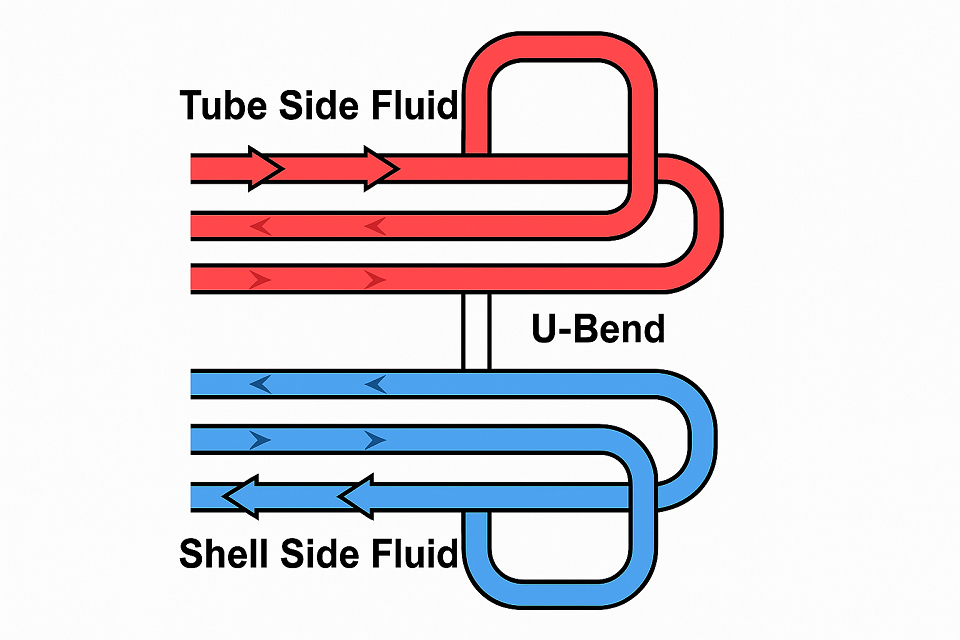
This layout allows the coldest fluid to meet the hottest one, maximizing the log-mean temperature difference (LMTD), which drives thermal exchange efficiency.
Maintenance Considerations and Design Life
Because hairpin heat exchangers are designed for high-performance applications, periodic maintenance is essential. Access ports, removable bundles, and corrosion monitoring points are often included for:
- Mechanical cleaning of the tube side using pigs or brushes
- Chemical cleaning for scale or deposit removal on shell side
- Non-destructive testing (NDT) of return bends and tubes
- Replacement of baffles or gaskets
Design life typically ranges from 20 to 30 years, assuming regular inspection and proper material selection. In high-temperature or highly corrosive environments, materials like Hastelloy or duplex stainless steel may be chosen to extend service life.
Industry Applications: Where Hairpin Heat Exchangers Excel
Hairpin heat exchangers are particularly suited for:
- Crude oil preheating in refineries
- Ammonia and methanol synthesis in chemical plants
- Steam generation or condensation
- Thermal recovery systems in waste heat applications
Their compact footprint and ability to handle high pressure and temperature make them superior to shell-and-tube exchangers in specific process-critical applications.
Summary
Hairpin heat exchangers combine engineering precision with practical performance. Each core component—from the outer shell to the return bend—plays a specific, indispensable role in ensuring optimal thermal transfer, pressure containment, and longevity. Understanding these components not only aids in selecting the right exchanger but also ensures reliable performance, minimized downtime, and cost-effective operation.
How Does the U-Tube or ‘Hairpin’ Design Improve Heat Transfer Efficiency?
In industrial heat exchange applications, inefficient heat transfer leads to increased energy costs, reduced process yields, and oversized equipment. Engineers often struggle to maximize thermal performance while minimizing equipment footprint and pressure loss. The U-tube or “hairpin” heat exchanger design solves many of these challenges by introducing a compact, counter-current flow path that maximizes temperature differentials and heat exchange surface area without needing excessive space or complex piping systems. Understanding how this simple “U-shaped” tube configuration improves heat transfer efficiency is key to designing or upgrading thermal systems for optimal performance.
The U-tube or hairpin design improves heat transfer efficiency by enabling counter-current flow, minimizing thermal losses, and maximizing the temperature gradient across the heat exchanger length. The design also allows for thermal expansion compensation, reduces piping complexity, and ensures a compact footprint. The fluid in the tube side reverses direction via the U-bend, allowing hot and cold streams to maintain maximum temperature difference along the entire flow path, significantly enhancing the log mean temperature difference (LMTD) and overall heat transfer coefficient.
These thermal and mechanical benefits make the U-tube hairpin configuration the preferred choice for high-efficiency, high-pressure applications such as oil refineries, chemical processing plants, and energy recovery systems. Read on to uncover the physical principles, engineering details, and real-world results that make hairpin heat exchangers superior in performance.
Hairpin heat exchangers offer better thermal performance due to their counter-current flow design.True
The U-tube configuration enables a counter-current flow, which maintains a higher average temperature difference between the two fluids throughout the exchanger, leading to more efficient heat transfer.
Counter-Current Flow: Maximizing Temperature Gradient
The primary reason the hairpin or U-tube design boosts heat transfer efficiency is its counter-current flow mechanism. This configuration allows the coldest fluid to meet the hottest fluid, preserving the maximum temperature differential over the entire length of the heat exchanger. Unlike co-current flow (where fluids flow in the same direction and the temperature difference quickly diminishes), counter-current flow enables a higher log mean temperature difference (LMTD).
| Flow Type | Temperature Gradient | LMTD Efficiency | Common Use Case |
|---|---|---|---|
| Co-current | Decreases rapidly | Lower | Basic systems |
| Counter-current | Maintains gradient | Higher | Hairpin exchangers |
This enhanced thermal driving force means that for the same amount of exchanged energy, a counter-current (U-tube) exchanger requires less surface area or achieves higher thermal efficiency within the same space.
Compact Footprint: Better Use of Installation Space
Hairpin designs fold the heat exchanger flow path into a U-shape, which cuts the equipment length in half. This leads to:
- Reduced installation space (ideal for skid-mounted or offshore systems)
- Simpler structural support
- Lower piping and insulation costs
The return bend allows two passes of the same tube bundle within a single shell, eliminating the need for external return headers and providing better thermal packaging.
Enhanced Thermal Expansion Handling
In high-temperature services, differential expansion between the tubes and shell can cause mechanical stress that shortens exchanger life or leads to failure. The U-tube design naturally absorbs this stress because the tube bundle is flexible at the U-bend, allowing thermal growth without overstressing the tubes or shell.
| Feature | Benefit |
|---|---|
| U-Bend Flexibility | Reduces thermal stress |
| No Fixed Tube Sheet | Avoids expansion-induced failure |
| Simplified Maintenance | Easy tube inspection and cleaning |
Reduced Pressure Drop and Flow Optimization
The U-tube design, when paired with well-spaced baffles and optimized nozzle placement, allows laminar-to-turbulent flow transition with lower pressure drop compared to multi-pass straight-tube exchangers. This reduces pumping costs and enables operation across a broader range of flow rates.
Here’s a typical example comparing pressure drop between different designs:
| Exchanger Type | Pressure Drop (kPa) | Flow Velocity (m/s) |
|---|---|---|
| Straight Tube (multi-pass) | 45 | 2.5 |
| Hairpin U-tube | 32 | 2.3 |
| Plate Heat Exchanger | 60 | 3.0 |
Improved Maintenance Access
With a hairpin exchanger, one end is completely accessible, which is particularly beneficial for:
- Cleaning the inner tube side with brushes or chemical agents
- Eddy current testing of the U-tubes for corrosion or wall thinning
- Replacing or refurbishing individual tube sections without full disassembly
The removable bundle design commonly used in hairpin exchangers simplifies scheduled and emergency maintenance tasks, reducing plant downtime.
Real-World Case Study: Hairpin Exchanger vs Shell-and-Tube
Scenario:
A petrochemical plant needs to recover heat from a hydrocarbon stream to preheat a process feed.
| Parameter | Hairpin Exchanger | Traditional Shell-and-Tube |
|---|---|---|
| Heat Duty (kW) | 1,500 | 1,500 |
| Surface Area Required (m²) | 120 | 180 |
| Equipment Length (m) | 6 | 9 |
| Maintenance Interval (months) | 24 | 18 |
| CAPEX Cost | $110,000 | $95,000 |
| OPEX over 5 years | $35,000 | $60,000 |
Conclusion: Although the hairpin design required a slightly higher capital cost, its lower energy consumption, reduced pressure drop, and longer maintenance intervals made it the better investment over the equipment’s lifecycle.
Thermal Design Comparison Chart
| Design Metric | U-Tube Hairpin | Straight Tube Exchanger |
|---|---|---|
| Thermal Efficiency | ★★★★★ | ★★★ |
| Compactness | ★★★★★ | ★★ |
| Maintenance Accessibility | ★★★★☆ | ★★ |
| Pressure Drop | Low | Medium |
| Thermal Stress Accommodation | Excellent | Poor |
Summary
The U-tube or hairpin design in heat exchangers is more than a structural convenience—it’s a performance-boosting feature. By enabling counter-current flow, reducing thermal stress, optimizing flow paths, and minimizing equipment footprint, the design achieves superior heat transfer efficiency across various industries. This makes it a go-to solution for demanding environments where space, performance, and reliability are non-negotiable.
In Which Industries or Applications Are Hairpin Heat Exchangers Most Effective?
When standard shell-and-tube or plate heat exchangers fail to meet high-pressure, corrosive, or compact layout demands, many industries turn to hairpin heat exchangers. However, engineers and plant managers often overlook them due to lack of clarity on where these units outperform others. Choosing the wrong type of heat exchanger can result in frequent breakdowns, poor energy efficiency, and significant operational costs. Understanding the specific industries and conditions in which hairpin heat exchangers deliver superior performance is critical to long-term plant success and cost control.
Hairpin heat exchangers are most effective in industries such as oil and gas, petrochemicals, power generation, fertilizers, chemical processing, geothermal energy, and offshore platforms. These units excel in high-pressure, high-temperature, or space-constrained environments where efficient heat transfer and corrosion resistance are essential. Their U-tube design, robust construction, and compact footprint make them ideal for applications involving aggressive fluids, thermal recovery, or phase changes like condensation and vaporization.
From upstream oil processing to downstream specialty chemical manufacturing, hairpin heat exchangers consistently outperform in severe service conditions. Let’s explore their key application areas and the unique reasons why they dominate in each sector.
Hairpin heat exchangers are only suitable for low-pressure applications.False
Hairpin heat exchangers are actually ideal for high-pressure and high-temperature services, particularly in oil, gas, and chemical industries due to their robust construction and compact design.
Oil & Gas Industry: Upstream and Downstream Applications
Hairpin heat exchangers are extensively used in both upstream (exploration and production) and downstream (refining and petrochemicals) segments of the oil and gas industry. Their compact design allows installation on offshore platforms or FPSOs, where space is at a premium, and their high-pressure handling makes them suitable for critical processing like:
| Application Area | Function |
|---|---|
| Crude Oil Preheating | Transfer heat from hot product to feedstock |
| Sour Gas Condensation | Manage corrosive, high-pressure gas streams |
| Heat Recovery in Refineries | Reclaim energy from hot process fluids |
| Glycol Regeneration | Reboil and condense glycol used in dehydration |
Material selection in oil and gas applications often involves duplex stainless steel, Inconel, or Hastelloy, capable of withstanding hydrogen sulfide (H₂S) and CO₂-rich environments.
Petrochemical & Chemical Processing
In chemical manufacturing, especially where corrosive fluids, aggressive solvents, or high thermal gradients are present, hairpin heat exchangers are frequently chosen for:
- Ammonia synthesis loops
- Ethylene cracking recovery
- Aromatics production (BTX units)
- Solvent condensation systems
| Benefit in Chemical Plants | Description |
|---|---|
| Corrosion resistance | Custom alloy tubes withstand aggressive media |
| Thermal shock tolerance | U-bend absorbs rapid temperature swings |
| Compact for skid-mount integration | Enables mobile modular unit design |
In many cases, multi-pass tube configurations are used to increase heat transfer within a shorter exchanger length.
Power Generation and Waste Heat Recovery
Power plants, especially combined-cycle and cogeneration facilities, leverage hairpin exchangers for their ability to:
- Recover heat from turbine exhaust
- Preheat boiler feedwater
- Serve as condensers for steam turbines
- Operate in closed-loop organic Rankine cycles (ORCs)
| Power Plant System | Heat Exchanger Role |
|---|---|
| HRSG (Heat Recovery Steam Generator) | Superheating or condensing steam |
| Closed Loop Cooling | Removing heat from oil or fluids |
| Biomass & Waste to Energy | Energy reclamation |
Hairpin heat exchangers are well-suited for high-pressure steam service, where safety and mechanical integrity are non-negotiable.
Fertilizer Production (Ammonia, Urea, NPK)
The fertilizer industry involves highly reactive and corrosive substances such as ammonia, urea, and nitric acid, requiring rugged heat exchangers that can:
- Handle extreme temperatures (up to 600°C)
- Resist nitrogen-based chemical corrosion
- Fit into tall, narrow process towers
| Fertilizer System | Hairpin Functionality |
|---|---|
| Urea Synthesis | Condensation and gas separation |
| Ammonia Loop | Waste heat recovery and temperature control |
| Nitric Acid Process | Preheating air or oxidizing gases |
Hairpin exchangers offer a low-maintenance alternative to plate or spiral heat exchangers in these highly corrosive environments.
Geothermal and Renewable Energy Systems
Hairpin heat exchangers are increasingly used in renewable energy applications, particularly:
- Geothermal brine recovery
- Organic Rankine cycles (ORC)
- Solar thermal storage systems
In geothermal applications, the exchanger must handle silica-rich or corrosive brines, often at pressures above 40 bar. The compactness and material flexibility of hairpin units make them perfect for both binary cycle and flash cycle geothermal systems.
Offshore and Marine Applications
Space is extremely limited in marine and offshore facilities, making vertical hairpin units the ideal solution. Their benefits in this sector include:
- Resistance to saltwater corrosion
- Space-efficient vertical mounting
- Easy tube-side access for maintenance
| Offshore Use Case | Application |
|---|---|
| FPSO Process Trains | Preheaters, condensers, oil coolers |
| LNG Loading Stations | Heat exchangers for boil-off gas |
| Marine Engine Rooms | Lube oil and jacket water cooling |
Specialized designs include titanium tubes for seawater and graphite linings for chemical resistance.
Hairpin Heat Exchanger Applications Summary Table
| Industry | Application Focus | Design Advantage |
|---|---|---|
| Oil & Gas | Crude preheat, sour gas cooling | High pressure, corrosion resistant |
| Petrochemical | Condensation, solvent recovery | Alloy materials, thermal shock handling |
| Power Generation | HRSG, steam recovery | Steam/condensate handling, high efficiency |
| Fertilizer Production | Ammonia/urea loop heat exchange | Resistant to nitrogen compounds |
| Geothermal | Brine heat recovery | Compact, corrosion-tolerant |
| Marine & Offshore | Lube oil, jacket cooling, vapor recovery | Compact vertical mounting, seawater resistance |
Specialized Applications and Emerging Fields
Hairpin heat exchangers are also finding increasing adoption in:
- Hydrogen production and purification units
- Battery thermal management (coolant loop recovery)
- Pharmaceutical solvent condensation
- High-purity chemical manufacturing (USP grade)
Emerging trends also include modular skids with integrated hairpin exchangers for remote deployment in temporary processing fields or portable energy units.
Summary
Hairpin heat exchangers prove their value in industries where space, pressure, temperature, and corrosion resistance are major concerns. Their design flexibility, robust thermal performance, and ease of maintenance make them indispensable in oil refineries, petrochemical plants, power stations, fertilizer factories, geothermal systems, and offshore facilities.
What Are the Advantages of Hairpin Heat Exchangers Compared to Traditional Shell-and-Tube Designs?
Process engineers, plant designers, and procurement specialists often face a crucial decision when choosing between hairpin heat exchangers and traditional shell-and-tube designs. A poor choice can lead to excessive pressure drops, increased maintenance downtime, inefficient thermal exchange, or a footprint too large for the installation space. In demanding industrial environments—especially those involving high pressures, corrosive media, or limited layout room—hairpin heat exchangers often provide superior value. But what exactly makes them better in specific contexts?
Hairpin heat exchangers offer several key advantages over traditional shell-and-tube designs, including a compact footprint, higher thermal efficiency through counter-current flow, better thermal stress handling, easier maintenance, and flexibility for multi-pass configurations. Their U-tube design reduces overall length while maintaining effective surface area, supports higher pressure ratings, and simplifies expansion management. These features make them ideal for high-pressure, high-temperature, and space-constrained applications.
In the sections that follow, we’ll break down the core benefits of hairpin heat exchangers in detail—with data tables, comparative charts, and real-world engineering insights to help you make informed decisions.
Hairpin heat exchangers have a smaller footprint than shell-and-tube exchangers for the same heat duty.True
The U-tube configuration of hairpin exchangers allows for a more compact layout, offering the same or higher heat duty with reduced overall exchanger length.
1. Compact Design and Space Optimization
One of the most immediate advantages of hairpin exchangers is their compactness, achieved through the U-tube layout. This design folds the fluid path back on itself, allowing for two passes of flow in a shorter unit length.
| Feature | Hairpin Heat Exchanger | Shell-and-Tube Heat Exchanger |
|---|---|---|
| Total Unit Length | Shorter (U-tube folds path) | Longer (straight path) |
| Installation Footprint | Small | Large |
| Ideal for Modular Skids | Yes | Limited |
| Vertical Mount Capability | Excellent | Moderate |
In offshore, mobile, or space-constrained environments (e.g., FPSOs, remote plants), compactness directly translates to cost savings on structure, insulation, and transportation.
2. Superior Thermal Efficiency via Counter-Current Flow
Hairpin heat exchangers naturally support counter-current flow, which maintains a maximum temperature differential between the hot and cold fluids across the exchanger’s full length. In contrast, many shell-and-tube units operate in co-current or mixed flow modes.
| Thermal Parameter | Hairpin Design | Traditional Shell-and-Tube |
|---|---|---|
| Flow Orientation | Counter-current | Mixed/parallel/counter-flow |
| Log Mean Temperature Difference (LMTD) | Higher | Lower |
| Heat Transfer Efficiency | Excellent | Good |
This optimized temperature gradient results in better thermal performance per unit surface area, allowing for either smaller exchangers or reduced energy usage.
3. Flexible Tube Configurations & Multi-Pass Design
Hairpin heat exchangers are inherently modular, allowing for multiple tube-side passes without the need for complex internal baffling or flow dividers. Engineers can tailor the number of passes to increase turbulence, improve heat transfer coefficients, and reduce fouling risk.
| Configuration Option | Hairpin Heat Exchanger | Shell-and-Tube Heat Exchanger |
|---|---|---|
| 1-2-4 Tube Pass Flexibility | Yes | Limited |
| Expansion for Capacity | Easy with modular design | Complex piping modifications |
| Shell-Tube Flow Matching | Tunable | Often fixed |
This customizability allows process engineers to meet demanding heat duty requirements in limited space, especially in batch operations or variable flow conditions.
4. Thermal Expansion Stress Management
Thermal stress—caused by temperature gradients between shell and tubes—can lead to equipment failure or leaks. Hairpin exchangers use U-tube bundles, which can expand and contract freely without creating axial stress.
| Expansion Handling | Hairpin Heat Exchanger | Shell-and-Tube Heat Exchanger |
|---|---|---|
| Expansion Joint Required? | No | Often Yes |
| Thermal Stress Absorption | Excellent | Moderate |
| Risk of Tube Sheet Damage | Low | Higher |
By minimizing thermal stress, hairpin designs extend equipment life and reduce the risk of unscheduled downtime due to joint failures or fatigue cracks.
5. Ease of Maintenance and Inspection
Maintenance access is a major advantage of hairpin designs. With removable tube bundles, single-ended access, and simplified internals, hairpin heat exchangers allow for easier cleaning and inspection—especially important in industries handling fouling or corrosive fluids.
| Maintenance Feature | Hairpin Heat Exchanger | Shell-and-Tube Heat Exchanger |
|---|---|---|
| Bundle Removability | Yes | Sometimes |
| Access Points | One end | Two ends |
| Tube Inspection | Simple (straight view) | Complex (multiple passes) |
Maintenance cost reductions of 15–25% have been observed over a 5-year period in facilities that switched from shell-and-tube to hairpin exchangers in fouling environments.
6. Higher Pressure & Corrosion Handling
Hairpin units are built for extreme service. Their thick-walled construction, smaller diameter shells, and short flow paths make them ideal for:
- High pressure gas cooling
- Corrosive fluids (acid gas, amines)
- High-velocity steam condensation
| Operating Limit | Hairpin Design | Shell-and-Tube Design |
|---|---|---|
| Pressure Tolerance | Up to 1,500 psi or more | 600–1,000 psi typical |
| Corrosive Service Materials | Custom alloys, lined tubes | Customization more complex |
| Fluid Compatibility | Broad | Broad but more costly |
This makes hairpin exchangers especially attractive in oil, gas, and chemical plants, where safety and process uptime are critical.
7. Hairpin vs Shell-and-Tube: Engineering Summary Table
| Feature/Metric | Hairpin Heat Exchanger | Shell-and-Tube Heat Exchanger |
|---|---|---|
| Footprint | Compact | Large |
| Flow Configuration | Counter-current (standard) | Mixed |
| Thermal Expansion Handling | U-bend flexibility | Expansion joints required |
| Heat Transfer Efficiency | Higher (better LMTD) | Moderate |
| Maintenance Access | Easier (one-end access) | Two-end access |
| Multi-pass Tube Design | Highly flexible | Limited |
| Pressure Rating | Very high (up to 1,500 psi) | Typically moderate |
| Ideal Applications | High-pressure, tight space | General-purpose, large duty |
| Initial Cost | Moderate | Slightly lower |
| Lifecycle Cost (5–10 yrs) | Lower | Higher (maintenance-heavy) |
Case Study: Switching from Shell-and-Tube to Hairpin
Plant: Petrochemical Refinery in Texas
Original setup: Shell-and-tube exchanger for hydrocarbon vapor condensation
Problem: Frequent thermal stress-induced failures; long maintenance downtime
Switch: Installed hairpin heat exchanger with duplex stainless steel
Result:
- Heat transfer efficiency increased by 18%
- Maintenance downtime reduced by 40%
- Annual operating cost savings: $38,000
Summary
Hairpin heat exchangers present compelling advantages over traditional shell-and-tube designs in high-demand environments. From compact layout and superior thermal efficiency to easier maintenance and better mechanical resilience, they offer engineers a reliable, cost-effective alternative—especially in high-pressure, high-temperature, or space-constrained applications.
What Are the Key Factors to Consider When Selecting a Hairpin Heat Exchanger for Your Process?

Choosing the wrong heat exchanger can cause catastrophic results—ranging from equipment failure to lost production hours and excessive energy consumption. Process engineers, plant managers, and procurement teams often face the daunting challenge of balancing pressure ratings, thermal performance, corrosion resistance, and cost when selecting a heat exchanger. A miscalculation in flow rate or material compatibility can result in fouling, premature wear, or complete operational failure. Understanding the key selection criteria for hairpin heat exchangers is essential for optimizing performance, ensuring reliability, and maintaining compliance with industrial codes.
When selecting a hairpin heat exchanger, the most critical factors include heat duty, operating pressure and temperature, fluid properties (including corrosiveness and fouling potential), flow rates, allowable pressure drop, material compatibility, space constraints, and regulatory standards. Each of these parameters influences the design, configuration, and performance of the exchanger, and must be aligned with the specific needs of the process.
The better these factors are matched to the application, the longer the exchanger will last and the more efficiently it will operate. Let’s explore these considerations in depth, including the engineering logic behind them and how to apply real data during the selection process.
Material selection in a hairpin heat exchanger is irrelevant as long as the design meets pressure and temperature requirements.False
Material selection is critical, as it ensures corrosion resistance, thermal compatibility, and long-term durability. Inappropriate materials can lead to rapid degradation or failure even if design pressures are met.
1. Heat Duty (Q): The Fundamental Thermal Requirement
The heat duty (measured in kW or BTU/hr) defines the amount of energy that must be transferred between two fluids.
Formula:
Q = m × Cp × ΔT
Where:
- m = mass flow rate
- Cp = specific heat capacity
- ΔT = temperature difference
The heat duty directly affects:
- Surface area required
- Exchanger size and length
- Number of tube passes
| Heat Duty Range | Recommended Hairpin Configurations |
|---|---|
| < 250 kW | Single-pass, compact U-bend |
| 250–1,000 kW | Two-pass or multi-pass tube bundle |
| > 1,000 kW | Large-diameter or parallel units |
Pro Tip: If future process expansion is likely, select a modular design that allows scaling by adding a second hairpin in parallel.
2. Operating Pressure and Temperature
Hairpin exchangers are favored for high-pressure and high-temperature services, but proper rating is critical. Design pressures can exceed 1,500 psi (103 bar) and temperatures up to 600°C (1,112°F) with appropriate materials.
| Pressure Rating | Application Examples |
|---|---|
| Up to 20 bar | Food & beverage, HVAC |
| 20–100 bar | Oil refining, gas sweetening |
| 100–1500+ bar | Steam generation, ammonia synthesis |
Thermal expansion management must be considered in high-temperature applications. Hairpin units handle this naturally via U-bend tube flexibility.
3. Fluid Properties: Fouling, Corrosion, Viscosity
Understanding both shell-side and tube-side fluids is essential. Important parameters:
- Corrosiveness (pH, chloride content)
- Fouling tendency (scale, biofilm, sludge)
- Viscosity and density
- Phase (liquid, vapor, slurry)
| Fluid Type | Material & Design Strategy |
|---|---|
| Acid gas (H₂S, CO₂) | Inconel or duplex stainless steel tubes |
| High-viscosity fluids | Corrugated or finned tubes, wider spacing |
| Slurries or fouling fluids | Larger tube diameters, removable bundle design |
| Seawater or brine | Titanium or super duplex, anti-fouling coatings |
Pro Tip: If fouling is likely, request a design with easy access for mechanical or chemical cleaning.
4. Flow Rate and Flow Regime
Accurate flow rate data determines:
- Velocity inside tubes
- Pressure drop
- Heat transfer coefficient (via Reynolds number)
| Flow Regime | Reynolds Number | Design Response |
|---|---|---|
| Laminar | < 2,300 | May need turbulence-enhancing features |
| Transitional | 2,300–4,000 | Consider increased tube passes |
| Turbulent | > 4,000 | Best for heat transfer efficiency |
Flow rate also influences nozzle size, tube bundle diameter, and pressure drop allowances.
5. Pressure Drop Limitations
Each process has a maximum allowable pressure drop across the exchanger. Exceeding this value increases pump power requirements and operating cost.
| Exchanger Section | Typical ΔP Limits |
|---|---|
| Tube Side | 0.5 – 1.5 bar |
| Shell Side | 0.3 – 1.0 bar |
Hairpin designs generally have lower pressure drops compared to multi-pass shell-and-tube units due to optimized flow paths and fewer directional changes.
6. Material Compatibility
Choosing the right material ensures resistance to:
- Corrosion
- Erosion
- Thermal stress
- Pressure fatigue
| Common Materials | Suitable Fluids |
|---|---|
| Carbon Steel | Non-corrosive oils, steam |
| 316L Stainless Steel | Food-grade, mild acids |
| Duplex Stainless Steel | Chloride-rich or seawater |
| Inconel, Hastelloy | Highly corrosive or acidic environments |
| Titanium | Seawater, brine, organic acids |
Always consider galvanic compatibility between the shell and tubes if dissimilar materials are used.
7. Installation Environment and Space Constraints
Hairpin units are excellent for tight installations or skid-mounted systems. Consider:
- Vertical or horizontal mounting
- Weight and structural support
- Access for maintenance
- Clearance for tube removal
Space-limited sites benefit from vertical hairpin designs, which reduce required floor space by over 50% compared to horizontal shell-and-tube units.
8. Regulatory Compliance and Industry Standards
Your exchanger must comply with codes such as:
- ASME Section VIII Div 1 (Pressure vessels)
- TEMA (Tubular Exchanger Manufacturers Association)
- API 660 (Oil and gas applications)
- 3-A Sanitary (Food & pharmaceutical)
Failing to comply can result in failed inspections or insurance claims.
9. Maintenance Requirements and Accessibility
A good design allows:
- Easy tube inspection (from one end)
- Bundle removal without disconnecting piping
- Drain ports for cleaning
- Corrosion monitoring points
Ask your vendor if they offer features like hinged end covers or mechanical cleaning ports.
10. Cost of Ownership (Not Just Initial Price)
While hairpin exchangers may cost 5–15% more initially, they usually:
- Last longer (20–30 years)
- Require fewer repairs
- Operate at lower energy costs (due to pressure drop and efficiency)
- Offer faster maintenance turnarounds
| Cost Element | Shell-and-Tube | Hairpin Heat Exchanger |
|---|---|---|
| Initial CapEx | Lower | Slightly higher |
| Maintenance Cost (5 yrs) | Higher | Lower |
| Downtime Impact | Higher | Lower |
| Lifecycle ROI | Moderate | High |
Summary Table: Key Selection Criteria for Hairpin Heat Exchangers
| Selection Factor | Design Impact |
|---|---|
| Heat Duty (kW) | Tube size, surface area, number of passes |
| Pressure & Temperature | Wall thickness, material choice |
| Fluid Type | Tube diameter, alloy selection, fouling design |
| Flow Rate | Velocity, turbulence, nozzle sizing |
| Pressure Drop | Baffle design, number of passes |
| Material Compatibility | Corrosion and erosion resistance |
| Space Constraints | Orientation, footprint, access needs |
| Compliance Requirements | ASME, API, TEMA certification |
| Maintenance Needs | Bundle removability, access ports |
| Total Cost of Ownership | ROI, maintenance, energy efficiency |
In Conclusion
Selecting the right hairpin heat exchanger is a strategic decision that balances process demands, operational reliability, and lifecycle cost. By evaluating thermal requirements, fluid behavior, pressure limits, and installation constraints, you can ensure optimal performance and longevity. The more precise your input data, the better your exchanger will perform in the field.
Hairpin heat exchangers offer a smart, efficient, and durable solution for high-performance heat transfer across demanding applications. Their specialized design not only conserves space but also maximizes thermal efficiency under pressure.
Need expert guidance or a quote on a custom-built hairpin heat exchanger? Contact us today to speak with our engineering team and get the right solution tailored for your process.
FAQ
Q1: What is a hairpin heat exchanger?
A1: A hairpin heat exchanger is a type of shell and tube heat exchanger, typically consisting of two or more concentric tubes bent into a U-shape (or “hairpin”) to allow efficient heat transfer between fluids. This compact design enables high thermal performance in a smaller footprint, making it ideal for space-limited environments and high-pressure applications. Commonly used in industries like chemical processing, oil & gas, and power generation, hairpin heat exchangers offer excellent resistance to thermal stress and are easy to clean and maintain.
Q2: How does a hairpin heat exchanger work?
A2: The hairpin heat exchanger works by passing one fluid through the inner tube while a second fluid flows in the opposite direction through the annular space between the tubes. This counter-current flow maximizes thermal efficiency. The U-shape design ensures a longer flow path in a compact structure, promoting greater heat transfer. The exchanger’s ability to handle high pressures and temperatures makes it suitable for heavy-duty industrial applications.
Q3: What are the advantages of using a hairpin heat exchanger?
A3: Hairpin heat exchangers offer several advantages, including:
– Compact size: The U-shape reduces the overall footprint.
– High thermal efficiency: Counter-current flow design enhances heat transfer.
– Durability: Can withstand high pressure and temperature conditions.
– Ease of maintenance: The design allows for easier cleaning, especially in fouling-prone applications.
– Modular construction: Units can be configured for specific flow and temperature requirements.
Q4: In what industries are hairpin heat exchangers commonly used?
A4: Hairpin heat exchangers are commonly used in:
– Chemical processing: For heating and cooling of corrosive fluids.
– Oil & gas: For preheating crude oil or cooling refined products.
– Power generation: In steam generation or waste heat recovery.
– Petrochemical plants: Where compact and high-efficiency systems are required.
– Pharmaceuticals: In controlled heating or cooling of sensitive materials.
Q5: What is the difference between a hairpin heat exchanger and a standard shell and tube exchanger?
A5: While both are types of shell and tube heat exchangers, the hairpin version features a U-shaped design that allows for a longer tube length in a compact footprint. This contrasts with standard shell and tube designs that typically require more space for equivalent performance. Hairpin exchangers also allow for more efficient counter-current flow, improving heat transfer rates and performance in many industrial applications.
References
- Hairpin Heat Exchangers Explained – Thermopedia
- Hairpin Heat Exchangers – Kelvion
- Hairpin Heat Exchanger Design Guide – Thermal Processing
- Heat Exchanger Types – Engineering Toolbox
- Shell and Tube vs Hairpin Exchangers – Chemical Processing
- Heat Exchanger Fundamentals – U.S. Department of Energy
- Hairpin Heat Exchanger Overview – Exchanger Industries
- Heat Transfer Basics – ScienceDirect
- Benefits of Hairpin Heat Exchangers – Heat Exchanger Hub
- Applications of Hairpin Exchangers – HRS Heat Exchangers