When selecting a heat exchanger, many engineers and procurement specialists face uncertainty about which specifications truly matter. Making the wrong choice can lead to efficiency losses, system failures, or excessive operational costs. A mismatch in design and actual performance requirements could severely impact your process outcomes. To avoid these issues, understanding the key specifications during procurement is essential for ensuring optimal performance, reliability, and cost-efficiency.
The key specifications when purchasing a heat exchanger include heat duty, temperature ranges, flow rates, pressure drop limits, material compatibility, fouling tendencies, and installation space constraints. These parameters directly impact the exchanger’s performance, durability, and integration with your system, making them critical in the selection process.
Understanding these specifications not only helps you make better decisions but also improves operational efficiency and reduces long-term maintenance costs. Let’s break down the essential considerations and guide you toward selecting the right heat exchanger for your application.
What Is the Required Heat Duty and Why Is It Critical When Choosing a Heat Exchanger?
In industrial thermal processes, selecting an inappropriate heat exchanger can lead to catastrophic inefficiencies: excessive energy usage, under-heating or over-heating of process streams, and high operational costs. Many engineers and plant operators underestimate the consequences of overlooking heat duty during the selection phase. When the heat duty is miscalculated, the chosen heat exchanger may either fail to meet processing requirements or cost significantly more to operate due to overdesign. Understanding what heat duty is, how it’s calculated, and why it plays a central role in equipment design is essential to ensuring operational efficiency and process reliability.
Heat duty is the amount of thermal energy that must be transferred from one process stream to another in a heat exchanger to meet the desired temperature change and process goals. It is typically measured in kilowatts (kW) or British Thermal Units per hour (BTU/hr). Knowing the precise heat duty is critical because it directly determines the size, type, and material specifications of the heat exchanger required to achieve effective heat transfer without energy losses or system failures.
If you want to ensure your thermal system meets production targets and energy efficiency standards, knowing the required heat duty is the cornerstone of heat exchanger selection. Misjudging this value leads to poor heat transfer performance, equipment oversizing or undersizing, and long-term operational inefficiencies. Let’s dive deeper to fully understand the criticality of heat duty and how it shapes the technical and economic landscape of heat exchanger design.
Heat duty is the most important parameter in heat exchanger design.True
Heat duty defines the energy transfer requirements and directly determines the type, size, and performance expectations of a heat exchanger.
Understanding the Concept of Heat Duty in Heat Exchanger Design
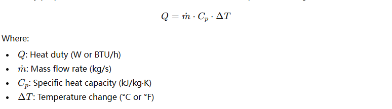
Heat duty is the quantification of thermal energy required to bring a process stream from one temperature to another. It arises from the First Law of Thermodynamics and is an application of the energy balance across the heat exchanger. The general formula for sensible heat transfer is:
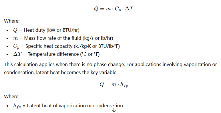
Depending on the type of process—cooling, heating, evaporation, or condensation—the way heat duty is calculated will vary. Every fluid, temperature range, and flow rate combination leads to a unique heat duty requirement. It’s essential to define this early in the engineering phase, as everything from surface area to material thickness depends on it.
Common Industrial Fluids and Their Heat Duty Characteristics
| Process Fluid | Typical Flow Rate (kg/s) | (C_p) (kJ/kg·K) | Typical ΔT (°C) | Approx. Heat Duty (kW) |
|---|---|---|---|---|
| Water | 2.5 | 4.18 | 35 | 366.5 |
| Steam | 1.2 | – (latent heat) | Phase Change | 2675.4 |
| Thermal Oil | 1.0 | 2.0 | 60 | 120 |
| Air | 3.0 | 1.005 | 70 | 211 |
This table gives a clear idea of how varying process parameters affect the heat duty. It also illustrates that two fluids with identical flow rates but different properties require different heat exchanger designs.
Why Is Heat Duty Critical for Heat Exchanger Selection?
When specifying a heat exchanger, heat duty determines the required surface area, thermal design (counterflow vs parallel flow), and selection of plate vs shell-and-tube vs spiral configurations. An undersized exchanger will result in insufficient heat transfer, reducing process output and requiring auxiliary heating or cooling. Oversizing leads to excessive capital costs and poor turndown ratios.
Let’s look at the design implications of heat duty in various heat exchanger types:
Heat Duty Impact on Different Heat Exchanger Types
| Exchanger Type | Heat Duty Range (kW) | Suitability Based on Duty | Typical Application Example |
|---|---|---|---|
| Plate Heat Exchanger | 10 – 10,000 | Ideal for medium duties | Dairy pasteurization, chemical fluids |
| Shell-and-Tube | 100 – 100,000+ | Best for high duties | Oil refineries, power generation |
| Air Cooled Exchanger | 500 – 50,000 | High duty + outdoor use | Gas compression, turbine cooling |
| Double Pipe | < 500 | Low to moderate duties | Small chemical batch operations |
The efficiency of the selected equipment depends on aligning the heat duty with the exchanger’s inherent capabilities. A shell-and-tube exchanger, for instance, is oversized and costly for applications requiring only 200 kW. A plate heat exchanger might be ideal in such a case.
Real Case Study: How Heat Duty Mismatch Caused Process Failure
In a chemical manufacturing plant producing polymer emulsions, a newly installed plate heat exchanger was undersized due to an underestimated heat duty (calculated as 380 kW instead of the actual 620 kW). This resulted in:
- 25% drop in batch heating rates
- 12-hour production delays weekly
- Increased energy consumption due to compensatory electrical heating
After recalculating and installing a properly sized plate-and-frame exchanger rated for 650 kW, process output stabilized, and energy costs dropped by 19% within the first quarter.
Heat Duty Calculation and Optimization – Key Design Steps
- Identify Process Requirements
Determine inlet and outlet temperatures, flow rates, and fluid types. Calculate Heat Duty
Use thermal formulas accounting for sensible or latent heat.Account for Safety and Fouling
Apply fouling factors and safety margins for long-term reliability.Match Heat Duty to Exchanger Capabilities
Use vendor selection tools or thermal simulation software.Validate with Real Process Data
Field measurements often differ from theoretical values due to losses.Review Energy Recovery Potential
Higher heat duties can often be used in heat recovery networks to reduce utility costs.
Advanced Considerations: Transient Heat Duty and Multi-Stream Exchange
In dynamic systems where temperature or flow varies with time (e.g., batch operations or seasonal feedstock changes), transient heat duty analysis becomes necessary. This involves time-resolved modeling of thermal energy demand and may necessitate modular heat exchanger systems that can operate flexibly across a duty range.
In multi-stream heat exchangers (e.g., in refineries), several heat duties must be simultaneously balanced, and optimization software such as Aspen HYSYS or HTRI Xchanger Suite is employed.
Conclusion
The required heat duty is not just a number—it’s the backbone of any thermal system design involving heat exchangers. By accurately determining this parameter and understanding its implications on size, type, cost, and energy performance, engineers can ensure that their systems run efficiently, economically, and reliably. Poor heat duty estimation is one of the top reasons for heat exchanger underperformance, but with careful calculations and proper tools, it’s entirely avoidable.
How Do Temperature Range and Approach Temperature Affect Heat Exchanger Sizing?
In thermal process design, many engineers make the mistake of focusing only on the flow rate or fluid type when selecting a heat exchanger. However, two often-overlooked but absolutely critical parameters — temperature range and approach temperature — have the most significant impact on heat exchanger sizing, cost, and performance. Misunderstanding these concepts can lead to purchasing oversized or underperforming heat exchangers, reduced process efficiency, and even safety risks. If you want to optimize your heat exchanger investment and ensure operational stability, you need a solid grasp of how temperature range and approach temperature drive the sizing process.
Temperature range is the difference between the inlet and outlet temperatures of a process fluid, while approach temperature is the smallest temperature difference between the hot and cold streams in a heat exchanger. Both parameters directly affect the required heat transfer surface area: a smaller approach temperature demands a significantly larger surface area, which increases the size and cost of the heat exchanger. Conversely, a wider temperature range improves thermal efficiency, allowing for a more compact design.
Understanding the role of temperature gradients in heat exchanger sizing can be the difference between optimal energy efficiency and costly overdesign. In the following sections, we’ll break down how these temperature factors influence surface area requirements, pressure drop, thermal performance, and ultimately, cost — helping you make smarter technical decisions.
A smaller approach temperature leads to a larger heat exchanger size.True
As the approach temperature decreases, the driving force for heat transfer is reduced, requiring a larger surface area to achieve the same heat duty.
The Role of Temperature Range in Heat Exchanger Sizing
The temperature range of each fluid in the exchanger determines how much thermal energy can be transferred, directly affecting the required heat exchanger design. It is calculated as:
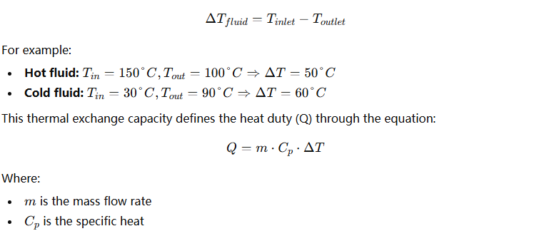
The larger the temperature range, the greater the amount of energy that can be transferred for a given fluid flow. In sizing terms, this means that you may require less heat transfer surface area because the exchanger can work with a higher driving force between fluids.
The Importance of Approach Temperature (ΔTmin)
The approach temperature is the minimum temperature difference between the outlet of one stream and the inlet of the other. It represents the thermal pinch point — the lowest allowable temperature difference across which heat is transferred.

A smaller approach temperature (e.g., 5°C) means that the two streams are getting very close in temperature, making heat transfer more difficult. This requires a much larger heat transfer area and a more complex exchanger design.
Impact of Approach Temperature on Required Heat Exchanger Area
| Heat Duty (kW) | Approach Temp (°C) | Required Area (m²) | Notes |
|---|---|---|---|
| 100 | 20 | 12 | Economical size |
| 100 | 10 | 20 | 67% increase in area |
| 100 | 5 | 36 | Tripled area from 20°C case |
| 100 | 2 | 65 | Near-impractical for compact HX |
This shows that reducing the approach temperature has a non-linear impact on required area — making it exponentially more expensive and bulky. This is why many engineers balance cost with performance by selecting a practical approach temperature (usually 5–15°C depending on process requirements).
Understanding Log Mean Temperature Difference (LMTD)
To design a heat exchanger effectively, we use Log Mean Temperature Difference (LMTD), which considers the temperature ranges and the heat exchanger flow configuration (counterflow or parallel flow):
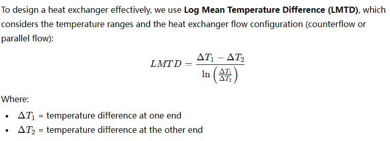
In counterflow exchangers, LMTD is higher, resulting in smaller required area for the same heat duty.
LMTD Comparison for Flow Arrangements
| Flow Type | ( \Delta T_1 ) (°C) | ( \Delta T_2 ) (°C) | LMTD (°C) |
|---|---|---|---|
| Parallel Flow | 50 | 10 | 26.3 |
| Counterflow | 50 | 10 | 36.8 |
The higher LMTD in counterflow improves heat transfer efficiency, allowing a smaller and cheaper exchanger for the same approach temperature.
Case Study: Cost Impact of Varying Approach Temperature
An ethanol distillation plant in South America was evaluating two designs:
- Design A: 10°C approach temperature, estimated surface area = 38 m², cost = $11,500
- Design B: 5°C approach temperature, area = 74 m², cost = $19,800
Although Design B had better thermal recovery, its additional capital cost and pressure drop made it unjustifiable. The team opted for Design A with a slightly lower recovery but better ROI.
Engineering Trade-Offs When Selecting Approach Temperature
While a lower approach temperature may seem attractive for energy savings or higher recovery, it has critical drawbacks:
- Larger exchanger size → Higher cost and footprint
- Higher pressure drop → Increases pumping energy
- Closer to thermal limits → Risk of fouling or non-condensation
- Longer delivery time → Due to custom sizing and materials
This means every design must balance:
- Capital vs operating cost
- Heat recovery vs pressure drop
- Space constraints vs energy targets
Tips for Engineers: Practical Approach Temperature Guidelines
| Application Type | Recommended Approach Temp |
|---|---|
| HVAC systems | 5–10°C |
| Process heating with steam | 10–20°C |
| Chiller systems | 2–5°C |
| Heat recovery systems | 3–7°C |
| High-efficiency condensers | <5°C |
Lower approach temperatures are technically possible, but only when justified by energy savings over the lifetime of the equipment.
Conclusion
Temperature range and approach temperature are the backbone of heat exchanger sizing. They determine how much energy can be transferred and how efficiently it can happen. A wider temperature range allows for more compact exchangers, while a smaller approach temperature requires a disproportionately larger surface area. Striking the right balance between thermal efficiency and economic feasibility is the key to smart heat exchanger selection. Overdesign leads to unnecessary costs, while underdesign compromises performance and safety.
Why Are Flow Rate and Velocity Important Specifications for Heat Exchanger Design?
In industrial process engineering, many system failures and underperforming heat exchangers are not caused by material selection or heat duty miscalculations—but by improperly accounted flow rate and velocity. Underrated flow rates can lead to fouling, while excessive fluid velocities cause erosion, pressure drops, and long-term mechanical stress. Whether you’re designing a heat exchanger for cooling water, process gases, or thermal oil, neglecting these specifications can lead to inefficient thermal performance and expensive repairs. This is why understanding the impact of flow rate and velocity is absolutely essential to effective and durable heat exchanger design.
Flow rate is the volume or mass of fluid moving through the heat exchanger per unit time, while velocity is the speed at which the fluid moves through the exchanger’s channels or tubes. Both parameters are critical because they directly affect heat transfer efficiency, pressure drop, fouling resistance, and mechanical integrity. A well-designed heat exchanger optimizes flow rate and velocity to ensure efficient thermal exchange while maintaining system reliability and longevity.
Designers and engineers must pay close attention to these two factors from the earliest design stages. Incorrect flow and velocity assumptions often lead to wrongly sized exchangers, increased maintenance, and compromised safety. In this article, we will explore in depth how flow rate and velocity influence the thermal, hydraulic, and mechanical aspects of heat exchanger design—and how to correctly size and balance them.
High flow rates always improve heat exchanger performance.False
While higher flow rates can enhance heat transfer, they also increase pressure drop and may cause erosion or vibration issues.
Understanding Flow Rate in Heat Exchanger Design
Flow rate is usually specified in either volumetric units (e.g., m³/h or GPM) or mass units (e.g., kg/h or lb/h), depending on the fluid type and system context. The heat transferred in a heat exchanger is directly proportional to the mass flow rate and the fluid’s temperature change:
The greater the flow rate, the more energy can be transported across the exchanger, assuming there’s a temperature gradient. However, this also means the exchanger must handle higher volumes, possibly requiring larger surface areas or flow passages to maintain target velocities and pressure limits.
Example of Heat Duty vs Flow Rate for Water (Cₚ = 4.18 kJ/kg·K)
| Mass Flow Rate (kg/s) | ΔT (°C) | Heat Duty (kW) |
|---|---|---|
| 1.0 | 25 | 104.5 |
| 2.0 | 25 | 209.0 |
| 2.0 | 15 | 125.4 |
| 3.5 | 20 | 292.6 |
This illustrates how increasing flow rate increases thermal energy transferred—but only when the exchanger is designed to accommodate it.
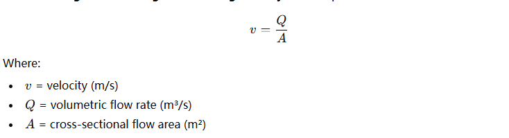
Why Fluid Velocity Matters in Heat Exchangers
Velocity is the speed at which fluid travels through the heat exchanger, typically in meters per second (m/s). While flow rate refers to quantity, velocity refers to how quickly that quantity moves through the exchanger’s internal geometry, such as plates, tubes, or fins.
Proper fluid velocity ensures turbulent flow, which significantly enhances heat transfer by reducing thermal resistance at the wall. However, too high a velocity can lead to:
- Tube erosion (especially in shell-and-tube exchangers)
- High-pressure drop
- Vibration and noise
- Pumping inefficiency
Meanwhile, too low a velocity can result in:
- Laminar flow (low heat transfer coefficients)
- Fouling and sedimentation
- Reduced thermal effectiveness
Recommended Velocity Ranges for Common Fluids
| Fluid Type | Recommended Velocity (m/s) | Notes |
|---|---|---|
| Water | 1.0 – 2.5 | Ideal for turbulence and low erosion |
| Oil | 0.5 – 2.0 | Lower due to higher viscosity |
| Steam | 10 – 30 | Very high for phase-change processes |
| Gases (air/N₂) | 10 – 25 | Requires high velocity for effectiveness |
| Slurry/particulate | 1.2 – 2.0 | Avoid sedimentation or erosion |
The Flow-Velocity-Pressure Drop Triangle
The relationships between flow rate, velocity, and pressure drop are closely intertwined. Increasing flow rate increases velocity, which increases friction losses, leading to higher pressure drop. An effective heat exchanger must strike a balance between thermal performance and hydraulic efficiency.
Chart: Velocity vs Pressure Drop for Plate Heat Exchanger (PHE)
| Velocity (m/s) | Pressure Drop (kPa) |
|---|---|
| 0.5 | 10 |
| 1.0 | 20 |
| 1.5 | 40 |
| 2.0 | 70 |
| 2.5 | 120 |
As this data shows, pressure drop increases exponentially with velocity. This not only raises pumping energy costs but may also exceed allowable system pressures, causing performance degradation or failure.
Case Study: Velocity Optimization in a Cooling System
A pharmaceutical plant upgraded its process water system using a shell-and-tube heat exchanger. The original design used low flow velocity (~0.4 m/s), which resulted in poor heat transfer and biofouling. After retrofitting with a reconfigured baffle arrangement and increasing flow to 1.5 m/s:
- Heat transfer improved by 38%
- Fouling frequency dropped by 60%
- Pumping energy increased slightly (~8%), but overall system efficiency improved significantly
This illustrates how minor adjustments to flow velocity can lead to major thermal performance improvements when properly engineered.
Design Implications: Tube Count, Plate Gap, and Channel Configuration
To control velocity, designers can manipulate:
- Number of tubes or plates
- Diameter of tubes (in S&T exchangers)
- Gap spacing (in plate exchangers)
- Flow arrangement (series vs parallel passes)
For instance, reducing plate gap increases velocity, but also raises pressure drop. Increasing passes can improve turbulence, but shortens flow path per pass. Every modification must consider the balance between thermal and hydraulic efficiency.
Conclusion
Flow rate and velocity are not just operational parameters—they are foundational design variables that determine the performance, efficiency, and reliability of your heat exchanger. Flow rate affects how much thermal energy can be exchanged, while velocity determines the effectiveness of that exchange and the durability of the equipment. Failing to account for either can lead to oversizing, fouling, erosion, and energy inefficiencies. Smart heat exchanger design optimizes both parameters to create systems that are thermally powerful yet mechanically robust.
What Role Do Pressure Drop Limitations Play in Selecting a Suitable Heat Exchanger?
In heat exchanger design, optimizing for maximum thermal efficiency alone can be a costly mistake if pressure drop limitations are overlooked. Many engineers and plant operators focus primarily on heat transfer performance, yet neglect to properly evaluate pressure constraints. The result? Systems that consume excessive pumping energy, suffer from flow disruptions, or even fail to operate entirely under real-world process conditions. Pressure drop is not just a by-product—it is a decisive factor that determines which type of heat exchanger is viable, how large it must be, and how much it will cost to operate long term.
Pressure drop limitations refer to the maximum allowable loss in pressure a fluid can tolerate as it flows through a heat exchanger. These limitations are critical because they directly affect the exchanger’s operating cost, pumping requirements, flow stability, and suitability for the given process. A well-chosen heat exchanger must achieve the desired heat transfer while staying within the specified pressure drop range to ensure reliability, efficiency, and mechanical integrity.
If your heat exchanger imposes a pressure drop beyond the system’s tolerance, it won’t matter how good its thermal performance is—it may destabilize upstream or downstream equipment, increase energy consumption, or create cavitation and vibration problems. That’s why pressure drop is a design constraint every engineer must manage intelligently. Keep reading to learn how pressure drop influences equipment choice, flow design, and operating economics.
High pressure drop is acceptable if heat transfer efficiency is maximized.False
While high pressure drop can improve heat transfer by promoting turbulence, it must remain within system limits to avoid excessive energy use, equipment stress, and flow instability.
What Is Pressure Drop in Heat Exchangers?
Pressure drop (ΔP) is the loss of fluid pressure as it travels through the channels, tubes, plates, or fins of a heat exchanger. It is typically measured in kPa (kilopascals) or psi (pounds per square inch). It results from:
- Friction against surfaces
- Directional changes in flow (baffles, turns)
- Flow constrictions or expansions
- Phase changes (especially condensation or boiling)
- Fouling or blockage over time
The pressure drop can be divided into:
- Internal Pressure Drop: Due to friction within the heat exchanger itself
- Nozzle Pressure Drop: From inlet and outlet port restrictions
The total pressure drop must not exceed the limit imposed by:
- The process system (e.g., pump or compressor head limits)
- The fluid properties (e.g., risk of cavitation in liquids or choked flow in gases)
- Energy efficiency requirements (high ΔP = high energy consumption)
Typical Pressure Drop Limits by Application
| Application Type | Acceptable Pressure Drop (kPa) | Notes |
|---|---|---|
| HVAC water systems | 20 – 50 | Emphasis on energy efficiency |
| Industrial cooling loops | 50 – 100 | Moderate ΔP for turbulence |
| Steam condensers | < 20 | Low ΔP to prevent backpressure |
| Gas systems | 5 – 30 | Gases are compressible |
| Oil refining processes | 100 – 300 | High ΔP accepted if justified |
As this table shows, acceptable pressure drop varies greatly by fluid type and industry. A one-size-fits-all approach is both risky and inefficient.
How Pressure Drop Affects Heat Exchanger Selection and Sizing
To achieve high heat transfer, designers often seek turbulent flow, which improves mixing and reduces thermal resistance. However, turbulent flow also increases pressure drop due to higher shear forces and eddies. The design challenge is to maximize turbulence and heat transfer without exceeding ΔP limits.
If the pressure drop limit is too low, the designer must compensate by:
- Increasing heat transfer surface area (larger unit)
- Using smoother internal geometries
- Reducing flow velocity
- Choosing counter-current over crossflow arrangements
If pressure drop is less of a constraint, more compact, high-efficiency units can be chosen.
Impact of Pressure Drop on Heat Exchanger Type Selection
| Heat Exchanger Type | Typical Pressure Drop Range | Suitable When… |
|---|---|---|
| Plate Heat Exchanger | 20 – 100 kPa | Medium ΔP allowed; high thermal efficiency |
| Shell-and-Tube | 10 – 250 kPa | Flexible ΔP; large area for high flow |
| Air-Cooled Exchanger | 5 – 50 kPa | Low ΔP requirement; gas or ambient cooling |
| Double-Pipe | < 20 kPa | Low ΔP and small-scale use only |
| Spiral Heat Exchanger | 50 – 200 kPa | High fouling fluids with moderate ΔP |
Pressure Drop vs Pumping Cost: A Long-Term Financial Tradeoff
Pressure drop isn’t just a design constraint—it’s an economic parameter. The higher the ΔP, the more energy your pumps or compressors will consume. Over the lifespan of a system, pumping energy can represent 25–40% of operational costs for some thermal systems.
Chart: Example of Pumping Power vs Pressure Drop
| Pressure Drop (kPa) | Pumping Power (kW) | Operating Cost ($/year)* |
|---|---|---|
| 20 | 0.75 | $1,800 |
| 50 | 1.9 | $4,500 |
| 100 | 3.8 | $9,200 |
*Assumes 24/7 operation, $0.06/kWh energy cost
As you can see, even moderate increases in pressure drop can have significant long-term cost implications. That’s why minimizing ΔP is a design objective for energy-conscious facilities.
Case Study: Overcoming Pressure Drop Challenges in a Chemical Plant
A chemical plant in Europe faced a bottleneck in one of its heat recovery loops. A plate heat exchanger was installed for maximum efficiency, but the actual pressure drop exceeded the pump capacity, resulting in cavitation and flow instability. The engineering team replaced the PHE with a spiral heat exchanger designed for lower pressure drop and higher fouling tolerance. As a result:
- System flow stabilized
- Pumping energy was reduced by 15%
- Heat recovery efficiency only dropped by 5%, which was deemed acceptable
This example highlights the importance of matching exchanger type to pressure drop constraints, not just heat transfer goals.
Pressure Drop Calculation and Mitigation Strategies
Engineers can calculate pressure drop using formulas specific to exchanger type. For example, for shell-and-tube:
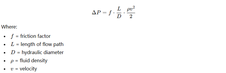
Ways to reduce pressure drop:
- Use fewer flow passes
- Increase flow area (more tubes, larger diameter)
- Optimize flow arrangement (U-tube, baffle design)
- Choose low-resistance exchanger types (e.g., S&T for large ΔP, PHE for compact systems)
Advanced software tools like HTRI, Aspen EDR, and SolidWorks Flow Simulation can also help simulate and optimize pressure drop during early design.
Conclusion
Pressure drop limitations are central to heat exchanger design—not secondary. They influence not just performance but energy use, equipment lifespan, and operational stability. Engineers must balance pressure drop against heat transfer needs, physical space, fouling potential, and lifecycle cost. Ignoring pressure constraints can result in overbuilt systems or catastrophic underperformance. By understanding and controlling pressure drop, you can ensure your heat exchanger delivers maximum efficiency with minimum risk.
How Does Material Selection Influence Heat Exchanger Performance and Longevity?
In heat exchanger systems, poor performance or premature failure is often traced back to one critical oversight: inappropriate material selection. Engineers sometimes choose materials based solely on cost or availability, neglecting to consider corrosion risks, thermal conductivity, fluid compatibility, or mechanical wear. The consequences? Corrosion failures, fouling, reduced heat transfer efficiency, or even catastrophic leakage—causing downtime, environmental harm, and costly repairs. Selecting the right material for your heat exchanger is not just a design choice—it’s a strategic investment in performance, safety, and equipment longevity.
Material selection directly affects a heat exchanger’s thermal performance, corrosion resistance, mechanical strength, and overall service life. Materials must be chosen based on operating temperature, pressure, type of fluid (corrosive, fouling, or clean), and maintenance expectations. High-conductivity materials improve heat transfer, while corrosion-resistant alloys ensure reliability in harsh environments. The right choice enhances durability and reduces lifecycle costs.
Don’t fall into the trap of “one material fits all.” A stainless-steel heat exchanger might perform well in clean water applications but fail rapidly in a chloride-rich brine stream. Material selection must be engineered around the specific process environment, not generic assumptions. Let’s explore how to make smart, technically sound choices that optimize both heat exchanger performance and life expectancy.
Titanium is the best material for all heat exchangers.False
While titanium is highly corrosion-resistant, it's not always ideal due to high cost, limited availability, and lower thermal conductivity compared to copper or aluminum.
How Material Properties Impact Heat Exchanger Design and Efficiency
Heat exchangers function by transferring thermal energy between two fluids across a solid barrier. The effectiveness of this barrier (the heat transfer surface) depends heavily on the thermal conductivity and corrosion resistance of the material used.
Key Material Properties to Consider
| Property | Why It Matters |
|---|---|
| Thermal Conductivity | Higher conductivity = faster, more efficient heat transfer |
| Corrosion Resistance | Prevents material degradation in aggressive or acidic fluids |
| Mechanical Strength | Determines resistance to pressure and vibration |
| Fabrication Suitability | Impacts welding, forming, and installation feasibility |
| Cost and Availability | Affects CAPEX and replacement parts strategy |
| Fouling Resistance | Slower fouling rate = longer maintenance intervals |
The perfect material balances thermal and mechanical performance with chemical resistance and economic viability.
Comparison of Common Heat Exchanger Materials
Properties of Common Heat Exchanger Materials
| Material | Thermal Conductivity (W/m·K) | Corrosion Resistance | Cost Factor | Common Applications |
|---|---|---|---|---|
| Copper | 385 | Low (poor in acidic/chloride) | Moderate | HVAC, potable water systems |
| Stainless Steel 304 | 16 | Good in general service | Moderate | Food processing, clean water |
| Stainless Steel 316L | 16 | Excellent in chlorides | High | Marine, pharma, chemical |
| Titanium | 21.9 | Exceptional (sea/brine/acid) | Very High | Desalination, chlorine service |
| Carbon Steel | 54 | Poor (rusts easily) | Low | Oil/gas (with inhibitors), low-cost loops |
| Hastelloy C-276 | 10 | Excellent for acids | Very High | Acid leaching, pickling, sulfuric processes |
| Aluminum | 237 | Moderate (pits in salt) | Low | Air-cooled exchangers, light-duty HVAC |
This table illustrates that no single material excels in all areas. Choosing wisely involves matching material traits to process conditions.
Impact of Material on Thermal Performance
Materials like copper and aluminum have excellent thermal conductivity, allowing fast energy exchange with minimal surface area. However, their corrosion resistance may not meet the needs of many industrial or chemical applications.
On the other hand, stainless steels and titanium have lower conductivity but higher chemical durability. To compensate for lower conductivity, engineers must increase surface area or enhance turbulence (e.g., via corrugated plates or extended fins).
Chart: Thermal Conductivity vs Required Heat Transfer Area
| Material | Conductivity (W/m·K) | Area Needed (Relative Units) |
|---|---|---|
| Copper | 385 | 1.0 (base reference) |
| Aluminum | 237 | 1.2 |
| Carbon Steel | 54 | 2.6 |
| Stainless 316 | 16 | 4.8 |
| Titanium | 21.9 | 4.1 |
| Hastelloy C-276 | 10 | 6.2 |
This shows how lower conductivity materials require larger surface area to deliver the same heat duty.
Material Compatibility and Corrosion Resistance
Selecting a material that resists the process fluid’s chemical nature is essential. Failures often occur when chlorides, acids, or oxidizers attack the heat exchanger surface.
Common Fluids and Compatible Materials
| Fluid Type | Compatible Materials | Incompatible Materials |
|---|---|---|
| Seawater / Brine | Titanium, 316L Stainless | Carbon Steel, Aluminum |
| Sulfuric Acid | Hastelloy, Tantalum | Stainless Steel, Copper |
| Potable Water | Copper, 304/316 Stainless | Carbon Steel |
| Hydrocarbons | Carbon Steel, Stainless | Aluminum (flammability risk) |
| Acetic Acid | Titanium, Hastelloy | Carbon Steel, Brass |
| Chlorinated Water | Titanium, PVDF (plastic exchangers) | Stainless Steel, Copper |
Fluid compatibility charts and corrosion rate data should be consulted in all cases. In highly corrosive environments, lifetime cost savings often justify high-end materials like Hastelloy or titanium.
Case Study: Material Failure Due to Improper Selection
A food-grade processing plant used 316 stainless steel plate heat exchangers for acidified fruit syrup lines. Within 18 months, visible pitting and leakage developed due to exposure to citric and malic acids in combination with cleaning-in-place (CIP) oxidizers. The exchanger was replaced with Hastelloy C-22, which has superior resistance to organic acids and oxidizing agents.
Results:
- Downtime reduced by 92%
- Lifespan extended by >5 years
- Maintenance intervals dropped from monthly to annually
This real-world case proves that selecting the right alloy eliminates corrosion-related losses and improves plant profitability.
Life Cycle Cost Considerations
While exotic alloys are more expensive upfront, they can reduce operational costs and downtime substantially over the lifecycle. The total cost of ownership (TCO) includes:
- Capital cost
- Installation
- Downtime from failure
- Maintenance frequency
- Replacement cost
Graph: TCO of Stainless Steel vs Titanium in Brine System (10-Year Horizon)
- Stainless Steel: Low initial cost, high replacement cost due to frequent failure (~every 2–3 years)
- Titanium: High initial cost, negligible maintenance, no replacement over 10 years
In this comparison, titanium reduced TCO by 37% despite a higher initial investment.
Custom Fabrication and Availability Constraints
Some materials, while theoretically ideal, may not be readily available for your exchanger type (e.g., spiral heat exchangers in Hastelloy) or may present fabrication challenges (e.g., titanium welding requires inert atmospheres). This limits your options, requiring either:
- Material compromise
- Design modifications
- Custom manufacturing with higher lead times
Consulting experienced manufacturers early in the design stage helps balance performance goals with production realities.
Conclusion
Material selection is one of the most influential decisions in heat exchanger design. It determines not just thermal efficiency but also the mechanical integrity, corrosion resistance, and operational lifespan of the system. A poor choice can lead to early failure and spiraling costs, while an informed selection matched to the process environment ensures maximum return on investment and trouble-free performance.
What Installation Constraints and Maintenance Considerations Should Be Factored In?
Heat exchangers may be thermally efficient and made of the perfect materials, but if they can’t be easily installed, accessed, or maintained, they become a liability instead of an asset. Many operational delays, unplanned shutdowns, and escalating maintenance costs stem not from design flaws—but from ignoring installation constraints and maintenance realities. A heat exchanger placed in a tight corner without lifting clearance or installed without maintenance valves can double servicing time and increase safety risks. Successful thermal system planning must go beyond performance specs to fully consider physical space, piping layout, access for cleaning, safety, and lifecycle maintenance strategies.
Installation constraints and maintenance considerations are critical because they determine the feasibility, cost, and safety of deploying and operating a heat exchanger. Key factors include space availability, orientation, structural support, access for cleaning or tube pulling, piping flexibility, drainage, isolation valve locations, and safe lifting or disassembly procedures. Ignoring these aspects can cause operational inefficiencies, extended downtime, and increased total cost of ownership.
Whether you’re working in a greenfield site or retrofitting a congested plant, ignoring these real-world constraints can render even the most technically sound heat exchanger unusable or uneconomical. This article will walk you through all the major installation and maintenance considerations—so your heat exchanger performs optimally and fits within your facility’s constraints.
Maintenance is only necessary if the heat exchanger shows performance issues.False
Preventive maintenance is essential to avoid performance degradation and extend the life of the heat exchanger before issues arise.
Core Installation Constraints to Evaluate
Proper installation of a heat exchanger requires more than just “does it fit in the space?” You must assess factors like piping layout, support structures, orientation, and ease of access.
Key Heat Exchanger Installation Constraints
| Constraint | Why It Matters | Recommended Approach |
|---|---|---|
| Available Floor Space | Determines whether unit fits and can be serviced | Check exchanger footprint and clearance zones |
| Lifting and Handling | Heavy exchangers require cranes, forklifts, or hoists | Ensure top clearance and safe lifting points |
| Piping Layout & Flexibility | Poor layout causes vibration, thermal stress, or leaks | Use expansion loops and flexible connectors |
| Structural Load Capacity | Some exchangers (e.g., S&T) are heavy and require reinforced pads | Confirm with structural engineer |
| Orientation Limitations | Vertical vs horizontal affects drainage and cleaning | Choose based on fluid properties and access |
| Drainage & Venting | Poor design traps fluid and causes corrosion or freezing | Include drain and vent valves at low/high ends |
| Nearby Equipment Access | Congestion hampers future maintenance or cleaning | Design for 360° clearance when possible |
Failing to account for these can lead to delayed commissioning, costly redesigns, or even safety hazards.
Maintenance Considerations: Plan for Access, Not Just Performance
Heat exchangers require regular maintenance such as cleaning, inspection, and gasket replacement. Designing without consideration for accessibility can result in hours or days of downtime for tasks that should take minutes.
Maintenance Access Requirements by Heat Exchanger Type
| Heat Exchanger Type | Typical Maintenance Tasks | Required Access Area |
|---|---|---|
| Shell and Tube | Tube cleaning, re-tubing, inspection | Tube bundle removal space (tube length) |
| Plate Heat Exchanger | Plate cleaning, gasket replacement | Front/back clearance for plate removal |
| Air-Cooled Exchanger | Fan blade service, fin cleaning | Top and side clearance for lift access |
| Spiral Heat Exchanger | Channel flushing, cover removal | Side clearance for cover swing-out |
| Double Pipe | Plug cleaning, replacement | Minimal access, depends on length |
Maintenance-friendly designs:
- Use removable covers, swing bolts, and inspection ports
- Add drain valves, venting ports, and lifting lugs
- Ensure nozzles are placed for easy disconnection
- Include flushing and bypass lines for in-place cleaning
Also consider: maintenance frequency, fouling potential, and cleaning methods (CIP, hydroblasting, chemical flush).
Real Case: Installation Failure Due to Ignored Constraints
In a dairy processing facility, a new plate heat exchanger was installed in a tight corner to save space. However, technicians discovered they had no room to remove the plates for periodic cleaning. The unit had to be disconnected and moved completely each time. Over one year:
- Maintenance time increased by 400%
- Gasket damage during handling rose sharply
- Downtime cost the company $26,000 in lost production
Eventually, the unit was relocated at additional cost, proving that installation oversight led to exponential OPEX increases.
Checklist for Installation Planning
Use this checklist during your design and installation phase:
- [ ] Have you verified the full footprint and service clearances (height, width, removal space)?
- [ ] Does the layout allow for proper lifting and maneuvering of the unit?
- [ ] Can the tubes, plates, or covers be removed without obstruction?
- [ ] Is there adequate ventilation around the exchanger?
- [ ] Are there drain and vent valves installed for both circuits?
- [ ] Is structural support verified for static and operational loads?
- [ ] Can utilities (steam, water, CIP, electricity) reach the unit easily?
- [ ] Are isolation and bypass valves installed for easy servicing?
These items prevent future headaches and ensure long-term maintainability.
Design for Maintainability: Smart Features to Include
Some best practices for maintenance-optimized heat exchangers include:
- Hinged or swing-out end covers for spiral and shell exchangers
- Segmental baffles that can be removed individually
- Quick-release clamps or tie-rods in plate exchangers
- Modular units that can be disconnected and serviced one module at a time
- Fouling monitors or pressure drop alarms to track performance decline
Also, select cleaning-compatible materials (e.g., stainless steel for CIP or caustic wash) and avoid deep crevices that collect residue.
Training and Documentation
No heat exchanger operates in a vacuum—your maintenance team must be trained and equipped. Ensure the following:
- Service manuals and exploded diagrams are provided
- Gasket specifications and torque guidelines are available
- Spare parts kits (gaskets, bolts, clamps) are stocked on-site
- Maintenance schedules are built into CMMS (Computerized Maintenance Management Systems)
These reduce human error, prevent damage, and improve safety.
Digital Twin and Maintenance Simulation (Advanced Tip)
For large or critical systems, use digital twin models to simulate:
- Serviceability
- Space conflicts
- Lifting paths
- Maintenance workflows
This ensures installability and maintainability before physical equipment arrives—saving time and costly modifications.
Conclusion
Installation constraints and maintenance considerations are often underestimated in heat exchanger projects, but they determine how effectively and economically your system operates over time. A thermally efficient design that is hard to install or service will ultimately cost more and perform worse. Smart engineering considers space, structure, access, utilities, and long-term maintenance from the very beginning. This leads to faster installation, lower downtime, and a more reliable process plant.
Choosing the correct heat exchanger involves more than just comparing prices or capacities; it’s about matching performance with your specific process conditions. Misjudging key parameters can lead to inefficiencies, downtime, and even system failure.
If you need expert advice or customized solutions for your heat exchanger requirements, contact us today. Let’s ensure your system runs smoothly with the right equipment.
FAQ
Q: What are the most important specifications when buying a heat exchanger?
A: Key specifications include design pressure, design temperature, heat duty (thermal load), flow rate, fluid properties (corrosiveness, fouling tendency), allowable pressure drop, material of construction, size constraints, maintenance access, and applicable codes or standards (e.g., ASME, TEMA, API).
Q: Why is design pressure critical in heat exchanger selection?
A: Design pressure defines the maximum pressure the exchanger can handle safely, ensuring structural integrity during operation. It must exceed the maximum operating pressure to account for pressure surges and comply with safety regulations.
Q: How does heat duty affect heat exchanger design?
A: Heat duty represents the total heat to be transferred between fluids. It directly influences the size, surface area, and configuration of the exchanger. Higher heat duties typically require larger or more efficient exchangers.
Q: What role does flow rate play in sizing a heat exchanger?
A: Flow rate affects the velocity of fluids, which impacts heat transfer efficiency and pressure drop. Proper flow rates are needed to maintain turbulence for effective heat exchange while avoiding excessive pressure loss or erosion.
Q: Why are material and corrosion allowance important in specification?
A: Material selection ensures compatibility with the process fluid to prevent corrosion or erosion. Corrosion allowance provides extra wall thickness to accommodate gradual material loss, extending the equipment’s service life in harsh environments.
References
- Heat Exchanger Specification Guidelines – Chemical Engineering Resources
- ASME Code for Pressure Vessels – ASME
- TEMA Heat Exchanger Standards – Tubular Exchanger Manufacturers Association
- Heat Exchanger Design Pressure Considerations – EnggCyclopedia
- Heat Duty and Sizing Basics – Engineering Toolbox
- Flow Rate and Pressure Drop in Heat Exchangers – API Heat Transfer
- Materials for Heat Exchanger Construction – Matmatch
- Corrosion Allowance in Equipment Design – Corrosionpedia
- Heat Exchanger Operation and Maintenance – Heat Exchanger USA
- Choosing the Right Heat Exchanger – Process Heating