In industrial settings such as oil refining, petrochemicals, gas processing, and chemical manufacturing, process towers and columns play a critical role in separation and purification operations. However, purchasing these components without clearly understanding the key specifications can result in costly inefficiencies, safety risks, or premature equipment failure. The complexity of process conditions—such as high pressures, corrosive media, or specific flow characteristics—means that selecting the wrong tower or column design can have significant operational consequences. To ensure safe, efficient, and long-lasting performance, it’s essential to identify and evaluate the most relevant technical and structural parameters before making a purchase.
The key specifications when purchasing process towers and columns include material of construction, design pressure and temperature, internal components, column diameter and height, tray or packing type, and compliance with relevant industry standards. These specifications ensure that the equipment is compatible with process requirements, chemical compatibility, thermal loads, and mechanical integrity.
Understanding these parameters not only ensures long-term equipment performance but also helps streamline procurement, reduce downtime, and meet environmental and safety standards. Keep reading to get a complete breakdown of the specifications you should verify before procurement.
What Materials of Construction Are Best for Process Towers and Columns Based on Chemical Compatibility?
In chemical processing industries, selecting the wrong material for process towers and columns can lead to catastrophic corrosion, unplanned downtime, and millions in repair or replacement costs. Towers exposed to aggressive chemicals, high temperatures, and varying pressures need materials that not only endure harsh conditions but also maintain structural integrity and chemical compatibility over time. The challenge lies in balancing material performance, cost, weldability, and maintenance. This article explores the most reliable materials of construction for process towers and distillation columns—tailored to the chemical environments they operate in—helping you avoid failure and optimize performance.
The best materials of construction for process towers and columns depend on the specific chemical environment, but commonly include stainless steels (304L, 316L) for general corrosion resistance, high-alloy materials (like Hastelloy, Inconel) for highly corrosive media, carbon steel for non-aggressive applications, and FRP or lined materials for special resistance to acids or solvents.
Understanding material compatibility is essential for long-term reliability, especially in aggressive chemical services such as acid gas removal, sulfur recovery, or hydrocarbon distillation. Read on to discover how the right material can significantly improve process safety, reduce lifecycle costs, and extend operational uptime.
316L stainless steel is suitable for most chemical processes in distillation columns.True
316L offers excellent corrosion resistance to many acids, chlorides, and solvents, making it one of the most widely used materials in chemical columns.
Material Selection Principles Based on Chemical Compatibility
When selecting a material of construction for process towers and columns, chemical compatibility is the first and most critical factor. However, temperature, pressure, mechanical load, and maintenance needs must also be considered.
The most common materials include:
- Carbon Steel (CS) – Low cost, good mechanical properties, but poor resistance to corrosive chemicals.
- Stainless Steel (SS 304, 316, 316L, 317L) – Improved corrosion resistance; 316L is the industry standard for chemical processing.
- Duplex Stainless Steel (2205, 2507) – Higher strength and better resistance to stress corrosion cracking than austenitic stainless steels.
- High-Nickel Alloys (Hastelloy C-276, Inconel 625, Alloy 20) – Excellent performance in highly corrosive and high-temperature environments.
- FRP (Fiberglass Reinforced Plastic) – Lightweight and corrosion-resistant; best for low-pressure acid or solvent environments.
- Lined Towers (Rubber-lined, Glass-lined, PTFE-lined Steel) – Used when base material cannot withstand the process media.
Table: Material vs. Chemical Compatibility Guide
| Process Chemical | Recommended Material | Remarks |
|---|---|---|
| Hydrochloric Acid (HCl) | Hastelloy C-276, PTFE-lined | SS corrodes rapidly in high HCl concentrations |
| Sulfuric Acid (H2SO4) | Alloy 20, 316L (low conc.), FRP | Avoid CS and SS at high temperatures |
| Nitric Acid | 304L, 316L, Titanium | Passivation layer forms naturally |
| Acetic Acid | 316L, Duplex SS | Good compatibility with austenitic SS |
| Ammonia (Anhydrous) | Carbon Steel | Dry ammonia is non-corrosive to CS |
| Chlorine (Cl₂) | Monel, Titanium, PTFE-lined | Extremely corrosive—use non-metallic linings |
| Caustic Soda (NaOH) | 316L, Alloy 20, FRP | Concentration and temp-dependent |
| Seawater or Brine | Duplex SS, Titanium | Avoid pitting and crevice corrosion |
Carbon steel is corrosion-resistant and suitable for all chemical towers.False
Carbon steel has poor corrosion resistance and is only suitable for non-aggressive services or where corrosion allowances are acceptable.
Key Material Performance Metrics
Mechanical Properties vs. Corrosion Resistance
Material selection must balance mechanical strength, thermal stability, and corrosion resistance. For example, while Titanium offers excellent resistance to seawater and oxidizing acids, its high cost and difficulty in fabrication limit its use to very specific services.
Chart: Material Cost vs. Corrosion Resistance
| Material | Relative Cost | Corrosion Resistance | Service Temperature |
|---|---|---|---|
| Carbon Steel | Low | Poor | Up to 427°C |
| 316L SS | Moderate | Good | Up to 870°C |
| Duplex SS 2205 | High | Very Good | Up to 316°C |
| Hastelloy C-276 | Very High | Excellent | Up to 1040°C |
| FRP | Low | Excellent (Specific) | Up to 93°C |
| PTFE-lined Carbon Steel | Moderate | Excellent | Up to 204°C |
Considerations for Specific Process Environments
Acid Gas Towers (e.g., CO₂, H₂S Absorbers)
In acid gas processing, corrosion due to acidic water or amines is common. 316L or Alloy 20 are preferred for lean/rich amine systems, while Hastelloy is used where H₂S partial pressure is high.
Fractionation and Distillation Columns
Distillation towers in hydrocarbon processing face fouling, high temperature, and corrosive trace compounds like mercaptans or chlorides. 304/316L, Duplex, or Alloy 20 are commonly used based on the presence of water, salts, and organic acids.
Solvent Recovery Towers
For organic solvent towers (e.g., acetone, MEK, ethanol), 316L or glass-lined carbon steel are appropriate, especially where cleaning and contamination are concerns.
FRP towers can operate at high temperatures above 300°C.False
FRP is typically limited to temperatures below 93–120°C due to resin limitations. For high temperatures, metal alloys are necessary.
Case Study: Chlor-Alkali Tower Retrofit
A chlorine processing plant faced severe pitting and material degradation in a brine purification column made from 316L stainless steel. The tower operated at 60°C with wet chlorine and trace HCl vapor. After metallurgical evaluation, the tower was retrofitted with a PTFE-lined carbon steel shell, resulting in:
- 90% reduction in corrosion rate
- Elimination of pitting after 2 years
- 40% lower cost than Hastelloy replacement
This highlights the importance of chemical-specific material compatibility and how lined solutions can balance performance and cost.
Additional Material Selection Tools
Compatibility Databases and Testing
Using corrosion compatibility charts from NACE International, ASTM, or vendor-specific databases (e.g., CorrosionData), engineers can verify compatibility. In critical cases, coupon testing or electrochemical testing is performed to validate performance under simulated service conditions.
Software Modeling
Tools like Aspen Materials Explorer or COMSOL corrosion simulation assist in modeling long-term corrosion rates and material lifespans in complex environments.
Summary
Material selection for process towers and columns must be tailored to the chemical nature of the process fluid, temperature, pressure, and mechanical loading conditions. While 316L stainless steel covers many general-purpose applications, high-chloride, acidic, or solvent-rich processes often demand Hastelloy, PTFE linings, or FRP. Carbon steel should only be considered in non-corrosive environments or where protective linings are viable. Matching chemical compatibility with performance and cost ensures long-term operational success and safety.
What Internal Components and Configurations Are Essential for Optimal Performance in Process Towers and Columns?
Poor internal design in process towers and columns is one of the leading causes of reduced separation efficiency, increased pressure drop, and premature column flooding or fouling. Without the right internals—correctly sized and configured—even a well-built tower shell will fail to deliver optimal throughput and purity. Process engineers often face challenges such as vapor-liquid maldistribution, channeling, and excessive entrainment, all of which compromise tower performance. The good news is that when chosen correctly, internal components like trays, packing, distributors, and mist eliminators can drastically improve mass transfer efficiency, pressure stability, and operational reliability. This article dives into each essential internal component and configuration strategy for distillation, absorption, stripping, and reaction towers.
The essential internal components for optimal performance in process towers and columns include trays (sieve, valve, or bubble-cap), random or structured packing, liquid distributors, redistributors, support plates, demister pads, and chimney trays. Proper configuration of these elements ensures efficient vapor-liquid contact, prevents maldistribution, minimizes pressure drop, and maximizes separation or reaction efficiency.
Knowing the function and placement of each internal element is critical for design or retrofit success. Whether you’re working with a distillation tower, absorber, or stripper, understanding how to select and configure these components can make or break your process efficiency.
Structured packing offers lower pressure drop and higher surface area than trays in most applications.True
Structured packing provides a large contact area with minimal obstruction to vapor flow, making it ideal for systems where pressure drop is critical.
Key Internal Components and Their Functions
1. Trays (Plates)
Trays promote vapor-liquid contact through staged equilibrium. Common tray types include:
- Sieve Trays – Perforated plates with no moving parts, ideal for low-to-moderate turndown ratios.
- Valve Trays – Have movable discs that adjust with vapor flow; provide better turndown and resistance to fouling.
- Bubble-Cap Trays – Oldest type, highly flexible with low leakage but higher pressure drop.
Each tray creates a theoretical stage. The more stages, the better the separation.
Tray Comparison Table
| Tray Type | Pressure Drop | Turndown Ratio | Efficiency | Maintenance |
|---|---|---|---|---|
| Sieve Tray | Low | 3:1 | Moderate | Easy |
| Valve Tray | Moderate | 10:1 | High | Moderate |
| Bubble Cap Tray | High | 15:1 | High | Complex |
Sieve trays are ideal for applications with very high turndown requirements.False
Sieve trays have limited turndown (3:1) due to fixed holes and are not suitable for wide flow variations.
2. Packing (Random and Structured)
Packing provides continuous contact rather than staged separation, ideal for absorption or stripping. Two main types:
- Random Packing: Includes Raschig rings, Pall rings, and saddles. Lower cost, easy to install.
- Structured Packing: Corrugated metal sheets arranged in organized layers. High surface area, low pressure drop, excellent for vacuum or reactive systems.
Packing Selection Chart
| Property | Random Packing | Structured Packing |
|---|---|---|
| Surface Area (m²/m³) | 100–300 | 250–750 |
| Pressure Drop | Moderate | Low |
| Cost | Low | High |
| Fouling Resistance | High | Moderate |
| Mass Transfer Efficiency | Moderate | High |
3. Liquid and Vapor Distributors
Even distribution of liquid and vapor is essential to avoid channeling, weeping, or dry spots. Types include:
- Trough type distributors
- Spray nozzles
- Orifice distributors (used for high liquid rates)
- Redistributors (installed periodically for tall packed beds)
Improper distribution leads to poor separation and maldistribution.
Illustration: Tower with Distributor and Packing Configuration
| Internal Component | Placement Function |
|---|---|
| Liquid Distributor | Above packed bed, ensures uniform flow |
| Packing Support Plate | Below packing to hold structure |
| Packing Retainer | Prevents upward fluid ejection |
| Redistributor | Mid-tower for tall packed beds |
| Demister Pad | Top of tower to remove entrainment |
Packed beds do not require liquid distributors for effective operation.False
Packed beds rely on precise liquid distribution to ensure full surface wetting and prevent channeling or dry zones.
4. Chimney Trays and Collector Pans
These are used in hybrid columns (tray plus packing) to collect liquid and redistribute it onto another section. They act as vapor-liquid disengagement zones and help transition between mass transfer sections.
Chimney trays typically include:
- Downcomers
- Vented caps or chimneys
- Weirs to control liquid level
Internals Configuration Strategy
The optimal configuration depends on process goals (e.g., separation purity, pressure drop limits, fouling potential, energy cost).
Configuration Guidelines:
- Use trays for processes requiring large throughput and better handling of solids or fouling.
- Use structured packing in vacuum or high-efficiency towers (e.g., fine chemical distillation).
- Install redistributors every 5–6 meters of packing height.
- Combine trays and packing when large vapor-liquid flow variations occur.
Table: Internal Configuration by Application
| Process Type | Recommended Internals | Key Considerations |
|---|---|---|
| Distillation | Sieve or Valve Trays / Structured Packing | Stage count, purity, pressure drop |
| Absorption | Structured Packing + Distributors | Wetting, contact area, mass flux |
| Stripping | Random Packing + Chimney Tray | Pressure drop, liquid holdup |
| Reactive Distillation | Structured Packing + Catalyst Holders | Contact time, temperature zones |
| Vacuum Distillation | Structured Packing | Minimize pressure loss |
Case Study: Refinery Debutanizer Optimization
A refinery upgraded its debutanizer column from sieve trays to structured packing due to fouling and high ΔP. Results:
- Pressure drop reduced by 45%
- Energy savings of 12%
- Product purity increased from 93% to 98%
This illustrates how internals upgrade can unlock performance without altering tower shell dimensions.
Demister pads are optional for process towers that involve vapor-liquid separation.False
Demister pads are essential to prevent liquid entrainment and protect downstream equipment like compressors and condensers.
Advanced Considerations
Material of Internals
- 304/316L Stainless Steel – Common for trays and distributors
- Plastic Packing – Used in corrosive low-temperature systems (HCl absorbers)
- Carbon Steel – Only for clean, non-corrosive systems
- PTFE or FRP Linings – For highly corrosive fluids
CFD and Simulation
Computational Fluid Dynamics (CFD) helps:
- Optimize distributor placement
- Predict vapor-liquid flow patterns
- Minimize maldistribution
Summary
The internal components of process towers—trays, packing, distributors, and support systems—are critical for achieving high separation efficiency and stable performance. Choosing the right configuration depends on your process type, flow rates, pressure/temperature conditions, and operational flexibility. Mistakes in internal design can lead to costly inefficiencies and product quality issues. But when done correctly, internals deliver reliable, high-throughput performance with reduced maintenance and energy costs.
How Do Design Pressure and Temperature Affect the Selection of Process Towers and Columns?
When engineers underestimate the importance of design pressure and temperature during the selection of process towers and columns, it can result in equipment failure, unplanned shutdowns, and even catastrophic safety incidents. These two parameters are not just numbers—they define the mechanical integrity, material selection, wall thickness, vessel sizing, and safety system requirements of the tower. Ignoring them means risking regulatory violations, structural fatigue, and multi-million-dollar repair cycles. This article explains in detail how design pressure and temperature influence the engineering, fabrication, and lifecycle of process towers and distillation columns—empowering plant designers and procurement teams to make optimal decisions.
Design pressure and temperature critically determine the material of construction, wall thickness, mechanical design codes (like ASME), nozzle and flange ratings, internal component selection, and safety margin for process towers and columns. Higher values typically demand stronger materials, thicker shells, and more robust internals—affecting both cost and long-term operability.
Understanding the consequences of pressure and temperature is key to achieving a safe, efficient, and compliant operation. Keep reading to uncover how these factors directly affect design choices from foundation to flange—and how to avoid over- or under-engineering.
Design pressure and design temperature are the primary mechanical criteria for tower design according to ASME standards.True
ASME Section VIII specifies that pressure vessels must be designed based on maximum expected pressure and temperature conditions to ensure structural integrity.
Core Concepts: What Are Design Pressure and Design Temperature?
Design Pressure
Design pressure is the maximum internal pressure that a tower or column is expected to experience under worst-case operating conditions, including normal operation and process upsets. It includes:
- Operating pressure + margin (usually 10-25%)
- Relief valve set pressure
- Vacuum or external pressure (for vacuum towers)
Design Temperature
Design temperature is the maximum (and sometimes minimum) temperature the tower materials and components will be exposed to under all operating conditions, including:
- Start-up and shutdown transients
- Reaction or heat exchanger failures
- Exothermic process excursions
How They Affect Tower Design: Overview Table
| Design Parameter | Impact on Tower Design | Notes |
|---|---|---|
| High Design Pressure | Increases wall thickness, weld requirements, support design | Follows ASME code stress values |
| High Design Temp | Affects material creep resistance, insulation, flange seals | Requires high-temperature-rated alloys |
| Low Temperature | May cause brittle fracture, requiring impact testing | Materials like carbon steel may become brittle |
| Pressure-Temp Combo | Determines flange class, nozzle thickness, internals | Must be analyzed together via ASME/EN code standards |
Design pressure is equal to operating pressure.False
Design pressure always exceeds operating pressure by a safety margin to accommodate process variations and ensure vessel integrity.
Influence on Material Selection
Material strength degrades at higher temperatures, while low temperatures increase the risk of brittle fracture in materials like carbon steel. Engineers must refer to allowable stress tables for different materials as per ASME Section II-D.
Table: Sample Allowable Stress Values by Temperature
| Material | Temp (°C) | Allowable Stress (MPa) |
|---|---|---|
| Carbon Steel (SA-516 Gr. 70) | 150 | 138 |
| Carbon Steel (SA-516 Gr. 70) | 400 | 108 |
| 316L Stainless Steel | 150 | 137 |
| 316L Stainless Steel | 600 | 65 |
| Hastelloy C-276 | 400 | 162 |
As temperature rises, allowable stress values decrease, requiring either a thicker shell or stronger material.
High-temperature operation always increases material strength.False
High temperatures generally reduce a material’s strength and resistance to pressure, necessitating thicker walls or upgraded alloys.
Mechanical Design Calculations Affected by Pressure and Temperature
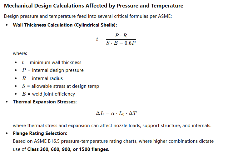
Case Study: High-Pressure Absorber Tower Design
A natural gas sweetening facility required a high-pressure absorber operating at 70 bar and 150°C with MDEA. Initial design with SA-516 Gr. 70 required 40 mm thick walls. However, due to frequent temperature cycling, stress corrosion cracking was a concern.
Solution:
- Material upgraded to Duplex 2205
- Wall thickness reduced to 25 mm
- Lifespan extended by 12 years
- Improved resistance to hydrogen sulfide cracking
This real-life case illustrates how correct material + optimized thickness = improved safety + reduced cost.
Effects on Internals and Accessories
High pressure and temperature affect:
- Tray and packing material (must resist deformation and corrosion)
- Nozzle reinforcements
- Gasket material (must survive thermal cycles and pressure spikes)
- Manway and flange ratings
Chart: Gasket Material Selection by Temperature
| Temp Range (°C) | Suitable Gasket Materials |
|---|---|
| -40 to 150 | Nitrile, EPDM |
| 150 to 400 | Spiral wound with graphite filler |
| 400 to 650 | Flexitallic, ceramic-based |
| >650 | Metal-to-metal with graphite inserts |
Safety Margin and Regulatory Codes
Regulations require incorporating design margins:
- ASME Section VIII mandates min. 1.1 to 1.3× safety factor
- API 650/660 codes used for specific tower types (e.g., refinery, petrochemicals)
- PED (EU), GOST (Russia), and other codes specify allowable temperature/pressure combinations
The ASME Code automatically selects tower wall thickness without pressure input.False
Engineers must input actual design pressure to calculate wall thickness; ASME does not make assumptions.
Summary
Design pressure and temperature are non-negotiable fundamentals in process tower and column engineering. They influence every aspect—from material and thickness to internals and accessories, and even compliance and safety systems. A small oversight here can lead to high-risk outcomes, but a well-informed design ensures optimal performance, extended service life, and regulatory compliance.
What Are the Critical Considerations for Sizing—Height and Diameter—of Process Towers and Columns?
Incorrectly sizing the height and diameter of process towers and columns can lead to disastrous performance issues—from flooding, weeping, and excessive pressure drop to incomplete separation or product contamination. Overdesign leads to unnecessary capital expenditure, while underdesign results in throughput limitations and safety risks. Yet many engineers underestimate the complex interplay of vapor-liquid flow dynamics, mass transfer requirements, pressure constraints, and tray/packing performance that drive column dimensions. This article outlines the critical engineering considerations that govern tower height and diameter, helping you size your columns accurately and cost-effectively based on your process goals.
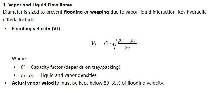
The critical considerations for sizing the height and diameter of process towers and columns include vapor and liquid flow rates, mass transfer requirements (number of theoretical stages), tray or packing type, allowable pressure drop, flooding velocity, turndown range, and mechanical design constraints. Height is primarily dictated by the number of equilibrium stages and tray spacing, while diameter is governed by vapor velocity and column capacity limits to avoid flooding and entrainment.
Tower sizing is not a one-size-fits-all calculation—it requires careful balancing of mass transfer, hydraulic, and mechanical parameters. Keep reading for expert-level guidance on designing your tower dimensions to maximize throughput, separation efficiency, and safety.
The height of a distillation column is determined mainly by the number of theoretical stages and tray spacing.True
Each theoretical stage corresponds to one tray, and the vertical space required for trays and disengagement zones determines total tower height.
Core Factors Affecting Tower Height
1. Number of Theoretical Stages
The required number of equilibrium stages depends on:
- Feed composition
- Desired separation (top and bottom purities)
- Reflux ratio (for distillation)
- Operating pressure
Methods like McCabe-Thiele (for binary systems) or Fenske-Underwood-Gilliland are used to estimate stage count.
2. Tray or Packing Type
- Tray Columns: Each stage equals one tray. Tray spacing is typically 18–24 inches (450–600 mm).
- Packed Columns: Use Height Equivalent to a Theoretical Plate (HETP), typically 0.3–0.6 meters for structured packing.
3. Additional Height Requirements
Additional vertical space is needed for:
- Feed and product draw trays
- Liquid disengagement zones
- Demister pads
- Reboiler and reflux drum connections
Example Calculation:
If a distillation requires 20 theoretical stages using valve trays with 24-inch spacing:
- Tray section = 20 × 24 in = 40 ft
- Add disengagement zones (top + bottom) = 10–15 ft
- Total height ≈ 50–55 ft
Packing eliminates the need for tower height calculation.False
Even with packing, height must be calculated using HETP values and added clearances for distributors and disengagement.
Core Factors Affecting Tower Diameter
2. Tray Design and Active Area
For tray towers, usable cross-sectional area depends on:
- Downcomer area (non-active)
- Weir length and tray pressure drop
- Tray efficiency (70–90%)
For packing, packing factor and dry vs. wet pressure drop curves are used.
Table: Capacity Factors (C) for Sizing
| Internal Type | C-Factor (ft/s) |
|---|---|
| Sieve Tray | 0.35–0.45 |
| Valve Tray | 0.40–0.50 |
| Structured Packing | 0.55–0.75 |
| Random Packing | 0.40–0.60 |
Example Diameter Sizing:
Assume:
- Vapor flow rate = 100,000 kg/h
- Vapor density = 2 kg/m³
- Liquid density = 800 kg/m³
- C = 0.5 ft/s
Calculate:
- (V_f) ≈ 0.5 × √[(800 – 2)/2] = 0.5 × √399 = 0.5 × 19.98 ≈ 10 ft/s
- Safe operating velocity = 85% × 10 = 8.5 ft/s
- Cross-sectional area = Flow / (ρ × V) ⇒ use to find diameter
Tower diameter is unrelated to flooding velocity.False
Tower diameter is directly based on allowable vapor velocity, which is governed by flooding limits to prevent operational instability.
Summary of Critical Design Parameters
| Parameter | Affects Height | Affects Diameter | Notes |
|---|---|---|---|
| Theoretical Stage Count | ✔ | Based on separation and process purity | |
| Tray Spacing / HETP | ✔ | Determines vertical space required | |
| Vapor Flow Rate | ✔ | Key to prevent flooding and entrainment | |
| Liquid Flow Rate | ✔ | Affects downcomer size and liquid load on trays | |
| Pressure and Temperature | ✔ | ✔ | Affect fluid properties, tray/packing design |
| Internal Type | ✔ | ✔ | Tray vs. packing affects both height and diameter |
| Fouling / Cleaning Access | ✔ | ✔ | Influences spacing and diameter for maintenance |
Real-World Case Study: Column Debottlenecking
A petrochemical plant experienced repeated flooding in an absorber. After review:
- Original tower diameter: 1.2 m
- Vapor load exceeded 90% of flooding velocity
- Recommended new diameter: 1.6 m with upgraded structured packing
- Capacity increased by 35% with no change in tower height
This highlights how diameter is critical for maintaining hydraulic stability—not just for capacity but also reliability.
Height-to-Diameter (H/D) Ratio Considerations
- Typical H/D ratio: 10:1 to 25:1
- Taller columns (high H/D) need wind bracing, better foundations
- Wide columns (low H/D) increase material costs and structural loads
Optimal range depends on process goals, seismic/wind design codes, and fabrication limitations.
Chart: Effects of Height and Diameter
| Design Concern | Increase Height | Increase Diameter |
|---|---|---|
| More stages needed | ✔ | |
| Higher throughput | ✔ | |
| Reduce pressure drop | ✔ | |
| Reduce column footprint | ✔ | |
| Improve safety factor | Both | Both |
Increasing tower height always improves separation efficiency.False
Separation depends on stage efficiency, not just height; overheight without added stages doesn't enhance performance.
Other Critical Considerations
- Mechanical Limitations: Tall towers require thicker shells due to wind loads.
- Transportation Limits: Columns over 4.5 meters in diameter may need field fabrication.
- Thermal Gradients: Large diameters may cause uneven temperature profiles.
- Internals Accessibility: Diameter must allow for human entry for inspection or cleaning.
Summary
Tower height and diameter must be sized through precise calculations involving vapor/liquid flows, mass transfer needs, tray or packing types, allowable pressure drop, and operational flexibility. Height determines number of stages and spacing, while diameter is driven by flooding limits and throughput. Skipping this critical step leads to underperformance, overdesign, or safety risks.
Should You Choose Trays or Packing for Your Process Column, and How Do They Impact Performance?
Choosing between trays and packing for a process column is one of the most pivotal decisions in column design. If you make the wrong choice, it could cost you in energy inefficiency, poor separation, increased maintenance, or operational instability. Many engineers and plant managers face this dilemma during new builds, debottlenecking, or retrofits. But the good news is that once you understand the differences in hydraulic behavior, mass transfer efficiency, pressure drop, cost, and fouling tolerance, you can make a highly optimized selection tailored to your process goals. This article provides a detailed technical comparison of trays vs. packing—and how each affects column performance, economics, and operability.
Trays are best suited for high-capacity, dirty service, or when large turndown is required, while packing—especially structured packing—delivers higher separation efficiency with lower pressure drop and is ideal for vacuum systems, fine chemical separations, or revamps where energy efficiency is key. The choice significantly impacts pressure drop, throughput, flexibility, and separation performance.
Whether you’re designing a distillation tower, absorber, or stripper, understanding this choice is fundamental to achieving stable and efficient operation. Let’s dive deeper into how each option works—and when to choose one over the other.
Packing provides lower pressure drop and higher efficiency than trays in most applications.True
Packing offers continuous contact with high surface area, which improves mass transfer with minimal pressure drop—ideal for vacuum and energy-sensitive operations.
Trays vs. Packing: Functional Overview
Trays (Plates)
Trays, or plates, create discrete equilibrium stages by allowing vapor to bubble through a liquid pool. Each tray is a physical level inside the column that contributes to separation.
Types include:
- Sieve Trays (perforated plates)
- Valve Trays (movable discs that adjust with vapor load)
- Bubble Cap Trays (vapor directed through caps into liquid)
Packing
Packing provides a continuous contact surface between rising vapor and descending liquid. It can be:
- Random Packing (Raschig rings, Pall rings, Berl saddles)
- Structured Packing (corrugated metal sheets arranged in geometric patterns)
Each type affects column height, pressure drop, and efficiency differently.
Comparison Table: Trays vs. Packing
| Parameter | Trays | Packing |
|---|---|---|
| Mass Transfer Mechanism | Stage-wise | Continuous |
| Pressure Drop | Moderate to High | Low to Very Low |
| Efficiency (HETP) | 0.3–0.6 m/stage (typical) | 0.2–0.4 m for structured packing |
| Fouling Resistance | High (easier to clean) | Lower (can clog over time) |
| Turn-down Ratio | Excellent (up to 10:1 with valve) | Moderate (2–3:1) |
| Maintenance Access | Easy (can walk inside) | Difficult (must remove packing) |
| Mechanical Strength | High | Lower |
| Vacuum Suitability | Poor to moderate | Excellent |
| Capital Cost | Moderate | Can be higher for structured |
Trays are always more efficient than packing in every application.False
Packing, especially structured types, can achieve higher efficiency per unit height and lower pressure drop than trays, particularly in clean services.
Key Performance Impacts
1. Mass Transfer Efficiency
- Trays: Each tray represents a discrete equilibrium stage; hence, more trays = better separation.
- Packing: Efficiency is defined by Height Equivalent to a Theoretical Plate (HETP). Structured packing offers higher surface area, leading to better mass transfer.
2. Pressure Drop
- Trays: 3–7 mmHg/stage typical. Pressure drop accumulates quickly over many trays—problematic for vacuum.
- Packing: Often 50–75% lower pressure drop. Critical for systems like vacuum distillation or cryogenic air separation.
Chart: Pressure Drop vs. Column Height
| Column Type | Pressure Drop (kPa/m) | Efficiency (HETP) |
|---|---|---|
| Sieve Tray Column | 1.2–2.5 | 0.3–0.6 m |
| Structured Packing | 0.2–0.4 | 0.2–0.4 m |
| Random Packing | 0.5–1.0 | 0.3–0.6 m |
3. Fouling and Cleanability
- Trays are better in dirty services (e.g., slurry, suspended solids) due to easy access and cleaning.
- Packing may clog in fouling services and is harder to inspect.
Structured packing is better suited for fouling services due to its high surface area.False
Structured packing is more prone to fouling and is harder to clean, making it less suitable for dirty services compared to trays.
4. Turn-down and Flexibility
- Trays offer better turndown, especially valve trays (up to 10:1). Ideal for plants with variable flowrates.
- Packing offers limited turndown (2–3:1). Poor distribution at low flows affects performance.
5. Column Height and Footprint
- Packing provides higher efficiency per vertical length → shorter towers.
- Useful in revamps where increasing column height is not feasible.
- Trays require more space due to tray spacing (typically 18–24 inches).
Case Study: Vacuum Distillation Column Upgrade
A refinery upgraded a 50-stage vacuum column from sieve trays to structured packing. Results:
- Pressure drop reduced by 70%
- Increased throughput by 25%
- Achieved higher cut-point purity
The revamp allowed greater separation at lower operating pressure—crucial in vacuum distillation.
Application-Based Guidance
When to Choose Trays
- Wide turndown or fluctuating flows
- Dirty or fouling process streams
- High throughput applications
- Easier mechanical inspection required
- Lower CAPEX and simplified fabrication
When to Choose Packing
- Low-pressure or vacuum applications
- Energy-sensitive processes (cryogenics, fine chemicals)
- Retrofits where pressure drop must be reduced
- Need for high efficiency in a limited height
- Clean gas/liquid systems with consistent flow
Table: Recommended Internal Type by Process
| Process Type | Preferred Internal Type | Notes |
|---|---|---|
| Atmospheric Distillation | Trays | Handles high flow, good turndown |
| Vacuum Distillation | Structured Packing | Low pressure drop required |
| Absorbers/Strippers | Packing | Good efficiency with clean fluids |
| Hydrocarbon Separation | Trays or Structured Packing | Depends on capacity vs. efficiency |
| Reactive Distillation | Packing (structured) | Consistent phase contact needed |
| Fouling Systems | Trays | Easier to clean and maintain |
Cost and Installation Factors
- Packing may involve higher upfront costs, especially structured metal packing, but can reduce long-term energy costs.
- Trays may require more column height and result in higher pressure drops but offer ease of mechanical design and reliability in rough service.
Packing and trays can never be used together in the same column.False
Hybrid columns with trays in one section and packing in another are common to balance hydraulic and separation requirements.
Summary
Both trays and packing offer advantages—trays shine in high-flow, fouling-prone, flexible operations, while packing delivers high-efficiency, low-pressure-drop performance in clean and controlled services. Your choice should be based on process fluid properties, pressure drop limits, flow variability, cleaning frequency, and lifecycle cost. There is no universally better option—only what’s better for your specific case.
Conclusion
Choosing the right process towers and columns requires a clear understanding of your process requirements and engineering constraints. By carefully considering each specification—from materials and mechanical design to internals and sizing—you can ensure maximum efficiency, compliance, and safety across the lifecycle of your equipment.
📞 Contact Us
FAQ
What are the most important specifications when buying process towers or columns?
When selecting process towers and columns, key specifications include diameter, height, design pressure and temperature, material of construction, tray or packing type, corrosion allowance, and design code compliance (e.g., ASME, API). These specs ensure that the tower fits the process requirements, withstands operating conditions, and complies with safety standards.
How do pressure and temperature affect column design?
Design pressure and temperature dictate the mechanical strength and material choice of the column. Higher pressures require thicker walls and robust materials to prevent rupture. Temperature impacts thermal expansion, material resistance, and insulation needs. Accurate pressure-temperature specs are critical for long-term reliability and safety in chemical or gas processing systems.
Why is material selection critical in process column design?
Material choice affects a column’s resistance to corrosion, temperature, and pressure. Common materials include carbon steel, stainless steel, and exotic alloys like Hastelloy or Inconel. Selection depends on the chemical composition of fluids, operating environment, and maintenance expectations. Poor material choices can lead to premature failure and costly downtime.
What is the role of trays and packing in towers?
Trays and packing provide surface area for mass transfer between gas and liquid phases. Tray types (sieve, valve, bubble cap) and packing types (structured, random) are chosen based on pressure drop, efficiency, capacity, and fouling resistance. The right internal design enhances separation performance and reduces energy consumption.
Should I consider future expansion when selecting tower specifications?
Yes. Planning for future process changes or capacity increases can save costs in the long run. Oversizing key dimensions like diameter or including extra nozzles and manways can accommodate scaling without requiring new equipment. Consult engineering forecasts and allow flexibility in design for operational agility.
References
- Process Tower Specifications – https://www.cheresources.com/content/articles/design-of-distillation-columns – Cheresources
- Column Design Parameters – https://www.aiChE.org/sites/default/files/cep/2015/cep0815_column_design.pdf – AIChE
- ASME Pressure Vessel Codes – https://www.asme.org/codes-standards/find-codes-standards/bpvc-section-viii-rules-construction-pressure-vessels – ASME
- Selecting Tower Internals – https://www.metso.com/industries/process-industry/separation/tower-internals/ – Metso
- Tower Material Guidelines – https://www.corrosionpedia.com/materials-for-chemical-process-equipment/2/7517 – Corrosionpedia
- Process Column Design Considerations – https://www.chemicalprocessing.com/articles/2009/122/ – Chemical Processing
- Tray vs Packing Systems – https://www.knovel.com/web/portal/browse/display?_EXT_KNOVEL_DISPLAY_bookid=ID:kpDistColm1&VerticalID=0 – Knovel
- Distillation Column Materials – https://www.engineeringtoolbox.com/distillation-column-design-d_1034.html – Engineering Toolbox
- Heat and Mass Transfer in Columns – https://www.sciencedirect.com/topics/chemical-engineering/mass-transfer-column – ScienceDirect
- Future-Proofing Process Equipment – https://www.hydrocarbonprocessing.com/magazine/2020/october-2020/equipment-operations/future-proofing-process-plant-equipment – Hydrocarbon Processing