Selecting the wrong shell and tube heat exchanger can lead to operational inefficiencies, higher energy costs, and even equipment failure. Many industrial operators struggle with matching the right exchanger design to their specific thermal, mechanical, and operational requirements—resulting in poor performance, increased maintenance, and safety risks. Fortunately, understanding the key factors that affect the selection process can significantly improve your equipment’s reliability, performance, and lifecycle cost.
To select the right shell and tube heat exchanger for your application, you must carefully evaluate process requirements such as temperature range, pressure, fluid properties, fouling tendencies, and material compatibility. You should also consider exchanger type, flow configuration, design codes, and maintenance accessibility to ensure optimal thermal performance, safety, and cost-effectiveness.
Choosing the correct heat exchanger is not just a technical decision—it’s a strategic one. Keep reading to explore the essential criteria and engineering insights that will help you make the best possible selection for your process conditions and long-term performance goals.
What Are the Key Process Parameters to Consider When Selecting a Shell and Tube Heat Exchanger?
In process industries, improperly selecting a shell and tube heat exchanger can lead to excessive energy loss, inefficient heat transfer, fouling, corrosion, and even complete process failure. These consequences not only reduce performance but can also escalate maintenance costs and downtime. The good news? A carefully informed selection based on key process parameters can significantly improve system reliability and energy efficiency. This article unpacks those crucial parameters and gives you an expert-level guide to choosing the right shell and tube heat exchanger for your application.
The key process parameters to consider when selecting a shell and tube heat exchanger include: fluid properties (such as viscosity, density, and corrosiveness), inlet and outlet temperatures, flow rates, pressure drop limitations, thermal duty, allowable pressure and temperature ranges, fouling characteristics, and cleaning or maintenance requirements. These parameters directly affect the size, configuration, material selection, and design of the exchanger.
Understanding these critical parameters is just the beginning. In the following sections, we’ll dive deeper into how each factor impacts exchanger design, performance, and longevity, supported with tables, charts, and real-world application cases to give you a comprehensive technical perspective.
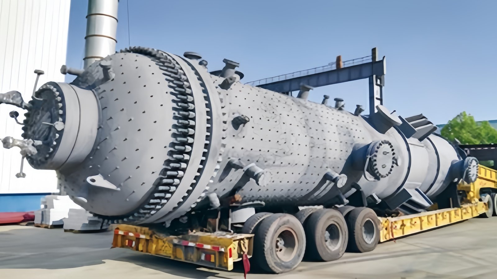
Shell and tube heat exchangers can handle very high pressures and temperatures.Истинный
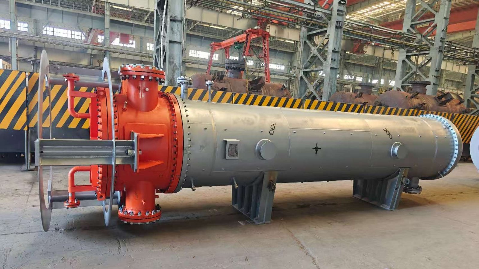
Shell and tube heat exchangers are commonly used in applications where fluids are under high pressure or high temperature, thanks to their robust mechanical design.
Fluid Properties and Their Impact on Exchanger Design
The fundamental starting point in selecting a shell and tube heat exchanger is a clear understanding of the fluid characteristics involved. Each property—density, viscosity, specific heat, thermal conductivity, phase (liquid or gas), and corrosiveness—can drastically affect the exchanger’s performance and configuration. For example, high-viscosity fluids typically require larger diameter tubes or lower velocities to reduce pressure drop, whereas corrosive fluids demand corrosion-resistant materials such as titanium, Monel, or Tantalum.
Table: Impact of Fluid Properties on Shell and Tube Design
| Fluid Property | Design Impact | Example Considerations |
|---|---|---|
| Viscosity | Influences pressure drop, tube sizing, flow regime | High-viscosity oils need larger tubes |
| Corrosiveness | Dictates material selection | Seawater requires titanium or Cu-Ni alloys |
| Thermal Conductivity | Affects heat transfer coefficient | Gases require longer length for the same duty |
| Фаза | Determines shell-side vs tube-side selection | Condensers: vapor in shell side |
| Fouling Tendency | Drives material and fouling allowance design | Crude oil needs fouling factors in calculations |
Beyond material choice, the layout of the exchanger—such as the number of tube passes or baffle spacing—is also impacted by fluid behavior. Highly fouling fluids benefit from designs that allow easy cleaning access (like removable tube bundles or U-tube configurations).
Thermal Duty, Flow Rate, and Temperature Profile
Thermal duty (Q), calculated as:
Q=M⋅CP⋅ΔT
where:
- m = mass flow rate,
- C_p = specific heat,
- ΔT = temperature difference,
serves as the backbone for sizing and performance evaluation. To meet the thermal duty, the required heat transfer area must be estimated based on the overall heat transfer coefficient (U), log-mean temperature difference (LMTD), and fouling factors.
Pressure Drop Constraints and Flow Configuration
Many processes have strict pressure drop limits, especially in pump-limited or vacuum systems. Pressure drop (ΔP) is a function of velocity, friction factor, tube diameter, and length. Exceeding allowable pressure drops can result in flow disturbances or equipment failure.
Table: Typical Pressure Drop Limits by Application
| Приложение | Max ΔP (Shell Side) | Max ΔP (Tube Side) |
|---|---|---|
| Cooling Water Systems | < 0.5 bar | < 0.7 bar |
| Oil and Gas Processing | < 1.0 bar | < 1.5 bar |
| HVAC Applications | < 0.3 bar | < 0.5 bar |
| Steam Condensers | < 0.2 bar | < 0.5 bar |
A balance must be achieved between high heat transfer coefficients (which benefit from higher velocities) and acceptable pressure drops. This requires iterative design supported by software such as HTRI or Aspen Exchanger Design & Rating (EDR).
Temperature and Pressure Ratings
Different applications require exchangers that can withstand extreme operating conditions. Standard TEMA designs accommodate pressures from 10 bar to 100 bar and temperatures from -50°C to over 600°C, depending on the material and construction.
Case Study:
In a refinery, a shell and tube exchanger was designed to cool cracked gas at 400°C and 30 bar pressure. Inconel-clad tubes were selected to handle the high temperature and corrosive environment, while expansion joints were incorporated to deal with thermal stresses.
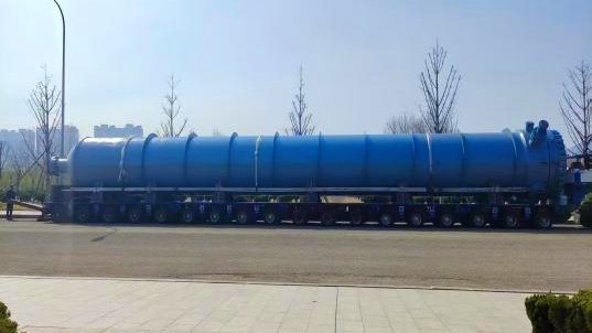
Shell and tube heat exchangers are typically limited to low-pressure applications.ЛОЖЬ
They are suitable for high-pressure applications, often used in power generation and petrochemicals.
Maintenance, Accessibility, and Cleanability
Cleaning requirements often dictate the choice between fixed tube sheet, floating head, or U-tube design:
- Fixed Tube Sheet: Lower cost, but cleaning shell side is difficult.
- U-Tube: Allows thermal expansion, but harder to clean the tube side.
- Floating Head: Easiest to clean, suitable for high-fouling fluids.
Maintenance downtime is critical in industries like pharmaceuticals or food processing, where hygiene and uptime are essential.
Table: Comparison of Shell and Tube Configurations
| Конфигурация | Maintenance Ease | Расходы | Fouling Suitability | Thermal Expansion Handling |
|---|---|---|---|---|
| Fixed Tube | Низкий | Низкий | Низкий | Бедный |
| U-Tube | Умеренный | Умеренный | Умеренный | Хороший |
| Floating Head | Высокий | Высокий | Высокий | Отличный |
In addition, TEMA class (R, C, B) should match the industry. TEMA-R, for instance, is for refinery use and allows for maximum accessibility and performance under severe conditions.
How Does Flow Configuration Impact the Performance of a Shell and Tube Heat Exchanger?
When a shell and tube heat exchanger fails to achieve its desired thermal performance, one of the most overlooked yet critical design factors is flow configuration. Choosing the wrong flow pattern—such as placing the wrong fluid on the shell side, or using parallel flow where counterflow is needed—can drastically reduce heat transfer efficiency, create imbalanced temperature profiles, and even damage equipment due to thermal stresses. Fortunately, understanding how flow configuration affects performance can help engineers make data-driven decisions that improve efficiency, energy savings, and system longevity.
Flow configuration in a shell and tube heat exchanger directly affects heat transfer efficiency, temperature distribution, pressure drop, and thermal stress management. Counterflow configuration typically yields the highest thermal performance by maximizing the log mean temperature difference (LMTD), while parallel flow offers simpler construction but lower efficiency. Crossflow and multi-pass configurations offer trade-offs between performance and compactness. The choice of flow arrangement—counterflow, parallel flow, crossflow, or multipass—must align with the process goals, fluid properties, and mechanical constraints.
Different flow configurations can either optimize or hinder heat exchange, depending on the thermal duty, fluid pressure limits, and temperature differentials. Read on to discover how to make the most effective choice for your application through a deep dive into thermal behavior, charts, case studies, and technical comparisons.
Counterflow configuration is more efficient than parallel flow in shell and tube heat exchangers.Истинный
Counterflow maintains a higher average temperature difference between the fluids, resulting in better heat transfer performance.
Understanding Common Flow Configurations
There are several main flow arrangements used in shell and tube heat exchangers:
- Parallel Flow (Cocurrent) – Both fluids enter from the same side and flow in the same direction.
- Counterflow (Countercurrent) – Fluids enter from opposite ends and flow in reverse directions.
- Crossflow – One fluid flows perpendicular to the other, often in segmental baffle designs.
- Multipass Flow – Tubes are divided into sections using partitions so that the fluid flows back and forth multiple times.
Table: Comparison of Flow Configurations in Shell and Tube Heat Exchangers
| Тип потока | Heat Transfer Efficiency | LMTD | Падение давления | Mechanical Complexity | Typical Use Cases |
|---|---|---|---|---|---|
| Противоток | Highest | Высокий | Умеренный | Умеренный | Energy recovery, high-duty |
| Параллельный поток | Низкий | Низкий | Низкий | Simple | Low-cost, compact systems |
| Crossflow | Середина | Середина | Середина | Середина | Compact layouts |
| Multipass Flow | High (Varies) | Высокий | Выше | Высокий | High heat load applications |
🔧 Log Mean Temperature Difference (LMTD) Formula
The LMTD is calculated using the following formula:
LMTD = [(Th,in – Tc,out) – (Th,out – Tc,in)] / ln[(Th,in – Tc,out) / (Th,out – Tc,in)]
Где:
- Tₕ,in = hot fluid inlet temperature
- Tₕ,out = hot fluid outlet temperature
- T𝚌,in = cold fluid inlet temperature
- T𝚌,out = cold fluid outlet temperature
Counterflow configurations allow for a higher and more uniform LMTD across the entire length of the exchanger.
Chart: LMTD Comparison Between Counterflow and Parallel Flow

In the chart above, it’s evident that counterflow offers a significantly higher temperature differential throughout the exchanger length, leading to better heat transfer performance.
How Flow Affects Pressure Drop and Pumping Power
Flow configuration doesn’t only influence temperature effectiveness—it directly impacts the pressure drop in the system. For example:
- Counterflow and multipass configurations often involve longer flow paths and higher turbulence, increasing pressure drop.
- Parallel flow has minimal pressure drop but suffers from poor thermal performance.
- Crossflow may offer a middle ground, often used when spatial constraints limit tube length or orientation.
Table: Pressure Drop Implications by Configuration
| Конфигурация потока | Shell Side ΔP | Tube Side ΔP | Pumping Energy Requirement |
|---|---|---|---|
| Противоток | Середина | Середина | Умеренный |
| Параллельный поток | Низкий | Низкий | Низкий |
| Crossflow | Variable | Середина | Variable |
| Multipass | Высокий | Высокий | Высокий |
To avoid excessive pump sizing and energy costs, pressure drop constraints must be evaluated alongside thermal efficiency. CFD simulations and flow modeling can help in predicting these outcomes.
Flow configuration has no effect on pressure drop in heat exchangers.ЛОЖЬ
Flow arrangement determines velocity, path length, and turbulence, all of which significantly impact pressure drop.
Thermal Stress and Mechanical Integrity
Thermal stress arises when there is a significant temperature difference between shell-side and tube-side fluids. If not managed properly through correct flow configuration, this can lead to:
- Tube expansion and contraction issues
- Gasket and seal failures
- Fatigue in materials over time
Противоток introduces gradual temperature gradients, helping mitigate localized thermal stress. In contrast, parallel flow can result in large temperature changes at the front end, creating hotspots and increasing mechanical stress.
Case Example:
In a sulfuric acid cooling application, using a U-tube counterflow design reduced thermal stress cracking and extended exchanger life by over 35% compared to a parallel-flow alternative used previously.
Flow Direction and Fouling Control
Flow arrangement also affects the fouling rate of the exchanger:
- High-velocity multipass flow reduces fouling but increases erosion risk.
- Vertical shell-side flow (gravity-assisted) helps in cleaning or draining.
- Reverse flow cleaning mechanisms can be implemented more easily in counterflow systems.
This makes flow configuration a maintenance and operability decision, not just a thermal one.
Table: Fouling Tendency and Flow Design
| Тип потока | Fouling Risk | Cleaning Ease | Application Fit |
|---|---|---|---|
| Противоток | Low to Moderate | Умеренный | Chemical processing, oil refining |
| Параллельный поток | Высокий | Высокий | Low-cost water exchangers |
| Multipass | Низкий | Низкий | Heavy-duty, high-fouling fluids |
| Crossflow | Середина | Умеренный | Air-cooled heat exchangers |
Making the Right Flow Configuration Decision
Selecting the best flow configuration isn’t a one-size-fits-all process. It requires evaluating trade-offs in efficiency, pressure drop, thermal stress, fouling, and mechanical complexity. Often, hybrid designs—such as counterflow in a multipass layout—offer the best of both worlds.
Совет эксперта
Always simulate your exchanger’s performance using flow modeling tools or thermal design software (e.g., HTRI, Aspen EDR). These tools factor in real-world variables like fouling resistance, tube layout, baffle cut, and flow-induced vibration.
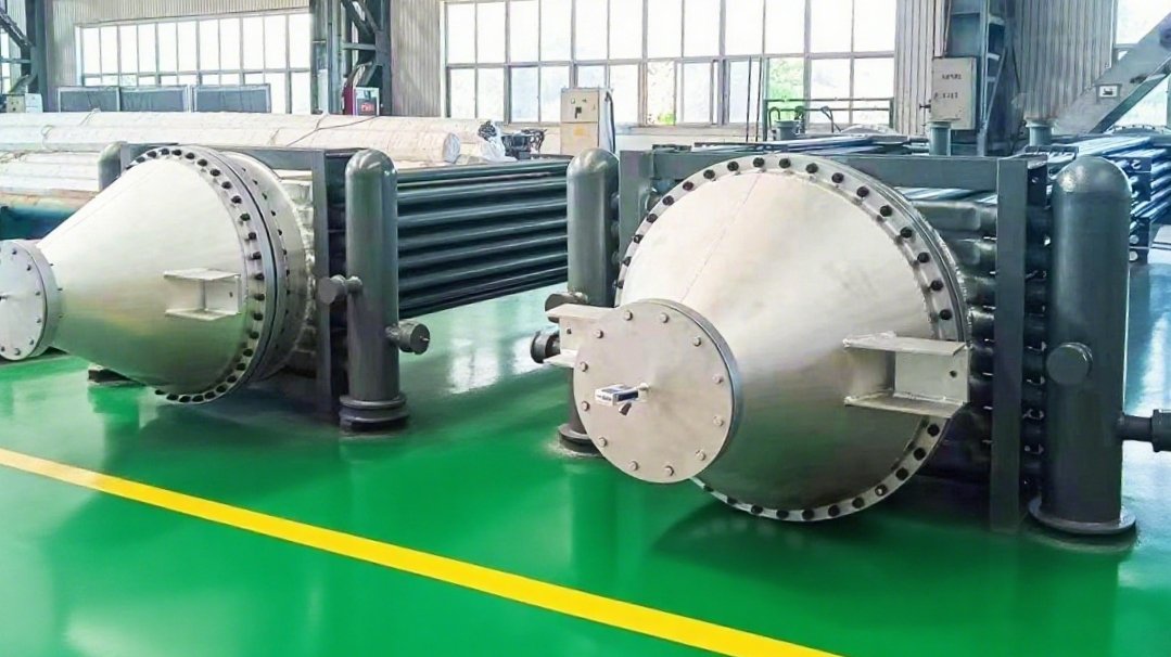
What Are the Main Types of Shell and Tube Heat Exchangers, and Which Should You Choose?
Selecting the wrong type of shell and tube heat exchanger can lead to massive inefficiencies, excessive fouling, frequent shutdowns, and even structural failure. Engineers often struggle to match exchanger types with application demands because of the complex trade-offs between thermal performance, maintenance, and cost. But with a clear understanding of the main exchanger types and their ideal use cases, you can confidently select the right design to maximize heat transfer efficiency and minimize long-term maintenance.
The main types of shell and tube heat exchangers are fixed tube sheet, U-tube, and floating head designs. Each type has unique mechanical and thermal characteristics. Fixed tube sheet exchangers are cost-effective but hard to clean on the shell side; U-tube exchangers handle thermal expansion well and are suitable for high-temperature differentials; floating head exchangers are best for high-fouling fluids and allow full cleaning access. The right choice depends on process temperature, pressure, fouling tendency, maintenance needs, and thermal expansion conditions.
While all three designs fall under the broader shell and tube category, each type serves different industrial applications—from high-purity pharmaceutical plants to harsh petrochemical operations. This article provides an expert-level guide with detailed data tables, use-case comparisons, and real-world insights to help you make an informed decision.
All shell and tube heat exchangers are built the same way regardless of application.ЛОЖЬ
There are several types of shell and tube heat exchangers—fixed tube sheet, U-tube, floating head—each with unique structural, thermal, and maintenance characteristics suited to different applications.
The Three Main Types of Shell and Tube Heat Exchangers
Shell and tube heat exchangers are categorized by their internal construction and tube-to-shell connection methods. The three most common types are:
- Fixed Tube Sheet
- U-Tube Bundle
- Floating Head (Removable Bundle)
Each type addresses different combinations of thermal expansion control, fouling resistance, and cleanability.
Table: Overview of Shell and Tube Exchanger Types
| Тип | Cleanability | Thermal Expansion Handling | Расходы | Best For |
|---|---|---|---|---|
| Fixed Tube Sheet | Tube-side only | Бедный | Низкий | Clean fluids, no thermal cycling |
| U-Tube | Tube-side only | Хороший | Умеренный | High ΔT, low fouling |
| Floating Head | Full access | Отличный | Высокий | High-fouling, aggressive cleaning required |
Let’s examine each in detail.
Fixed Tube Sheet Heat Exchanger
In this type, the tube bundle is permanently attached to the shell at both ends with welded tube sheets. Because of this construction, it’s not possible to remove the bundle or access the shell side for cleaning.
Преимущества:
- Simple, cost-effective design
- High pressure and temperature ratings with proper design
- Suitable for non-fouling services or when shell-side fluid is clean
Ограничения:
- Poor maintenance access on shell side
- Not suitable for fluids with high fouling tendencies
- Prone to thermal expansion stresses if tube and shell temperatures vary significantly
Applications: HVAC water cooling systems, hydraulic oil coolers, clean chemical services
Design Insight:
Fixed tube sheets require the addition of expansion joints if there is a large thermal gradient between shell and tube fluids. These joints increase complexity and cost, potentially negating the low-cost advantage.
Fixed tube sheet heat exchangers are ideal for heavily fouling fluids.ЛОЖЬ
They lack shell-side access, making them unsuitable for fouling fluids that require frequent cleaning.
U-Tube Heat Exchanger
This configuration uses a single tube sheet with tubes bent into a U-shape, allowing for thermal expansion without stress. The U-tube bundle is partially removable for inspection and cleaning on the tube side.
Преимущества:
- Excellent thermal expansion absorption due to tube flexibility
- Compact footprint with multi-pass tube arrangement
- Moderate cost compared to floating head designs
Ограничения:
- Tube side only accessible for cleaning; innermost bends are hard to reach
- Cannot use straight tube cleaning tools
- Tube bundle can be more difficult to fabricate and install
Applications: High ΔT processes, steam heating systems, moderate fouling fluids
Case Example:
In a steam-to-oil heating unit with frequent thermal cycling between 150°C and ambient, the U-tube design successfully absorbed expansion forces and extended service life compared to a previously failing fixed-tube design.
Floating Head Heat Exchanger
This is the most flexible and maintenance-friendly design. One end of the tube bundle is fixed, while the other is free to “float” inside the shell. This allows for unrestricted thermal expansion and complete disassembly for thorough cleaning.
Преимущества:
- Full mechanical cleaning access to both shell and tube sides
- Accommodates extreme temperature differences
- Ideal for dirty or fouling fluids
Ограничения:
- High initial cost due to complex construction
- Larger footprint
- More leak points due to additional sealing surfaces
Applications: Petrochemical processing, fouling crude oil systems, chemical recovery units
Design Insight:
Floating head designs come in variations (e.g., split-ring, packed floating head, and pull-through bundle) depending on the maintenance frequency and cleanliness level required.
Floating head heat exchangers are more expensive but easier to maintain in dirty fluid applications.Истинный
They allow full removal of the tube bundle and access for mechanical or chemical cleaning, making them suitable for fouling environments.
How to Choose the Right Type?
Choosing the appropriate type depends on five key criteria:
- Temperature Differential (ΔT)
- If ΔT > 50°C, consider U-tube or floating head.
- Fouling Propensity
- For fouling fluids, avoid fixed tube sheet; prefer floating head.
- Cleaning Requirements
- Require full access? Go for floating head.
- Cost Constraints
- Tight budget and clean fluids? Use fixed tube sheet.
- Maintenance Accessibility
- If frequent maintenance is anticipated, floating head or at least U-tube is necessary.
Table: Type Selection Guide Based on Process Needs
| Process Condition | Recommended Type |
|---|---|
| Clean fluids, stable temp | Fixed Tube Sheet |
| High temp difference | U-Tube |
| Highly fouling, dirty fluids | Floating Head |
| Low budget, low maintenance | Fixed Tube Sheet |
| Easy inspection required | Floating Head |
How Do Material Selection and Corrosion Resistance Affect Exchanger Reliability?
Corrosion is one of the silent killers in heat exchanger systems. Selecting the wrong material for the shell, tubes, or gaskets can cause rapid material degradation, internal leaks, contamination, and catastrophic equipment failure. These issues often result in unplanned downtime, costly repairs, or even safety hazards—especially in aggressive chemical or marine environments. However, by choosing materials with the appropriate corrosion resistance, engineers can dramatically extend the service life, minimize maintenance, and ensure long-term process reliability.
Material selection and corrosion resistance are critical to heat exchanger reliability because they determine the equipment’s ability to withstand chemical attack, erosion, temperature stress, and mechanical wear. Using corrosion-resistant alloys such as stainless steel, titanium, Hastelloy, or Cu-Ni ensures structural integrity, maintains thermal performance, and reduces unexpected failures. The right material depends on the process fluid properties, temperature, pressure, and fouling potential.
This article provides in-depth guidance on how different materials behave under various operating conditions, complete with corrosion rate data, material compatibility charts, and case studies to support optimal selection for exchanger longevity.
Material selection does not significantly impact heat exchanger reliability.ЛОЖЬ
Incorrect materials lead to rapid corrosion, leaks, and system failures. Proper material selection is fundamental to exchanger durability and performance.
Key Material Considerations in Heat Exchanger Design
Heat exchangers are exposed to diverse fluids—acidic, basic, saline, oxidizing, or reducing—each posing a unique threat to material integrity. Material compatibility affects not only corrosion resistance but also thermal conductivity, strength, cost, and ease of fabrication.
Common Materials and Their Corrosion Behavior
| Материал | Коррозионная стойкость | Типичные области применения | Расходы | Thermal Conductivity (W/m·K) |
|---|---|---|---|---|
| Углеродистая сталь | Poor in acidic/chloride media | Steam, clean water, low-cost applications | Низкий | ~54 |
| 304 Stainless Steel | Moderate, not chloride resistant | Food, pharma, mild chemicals | Умеренный | ~16 |
| Нержавеющая сталь 316L | Good resistance to chlorides | Marine, pharma, oil & gas | Умеренный | ~14 |
| Титан | Excellent in seawater, acids | Seawater, desalination, chlorine chemicals | Высокий | ~22 |
| Cu-Ni Alloys | Good marine resistance | Offshore, cooling towers | Умеренный | ~50 |
| Хастеллой С-276 | Excellent in oxidizers and acids | Harsh chemicals, acid recovery units | Очень высокий | ~10 |
The key is matching the corrosion resistance profile of the material to the exact chemical nature of the process fluids—considering not just pH, but temperature, velocity, and presence of suspended solids or gases.
Types of Corrosion and Their Impact on Exchanger Life
There are several forms of corrosion that can affect shell and tube exchangers. Each requires specific material defenses.
Table: Common Corrosion Types in Heat Exchangers
| Corrosion Type | Описание | Typical Causes | Preferred Material Solution |
|---|---|---|---|
| Uniform Corrosion | Even attack across surface | Acidic/basic environments | SS316L, Titanium, Hastelloy |
| Pitting Corrosion | Localized, pinhole-type corrosion | Chloride-rich water | Titanium, Hastelloy C-276 |
| Crevice Corrosion | Occurs in tight crevices or under gaskets | Stagnant, oxygen-depleted zones | Avoid crevices + use resistant alloys |
| Galvanic Corrosion | Between dissimilar metals in contact | Mixed material interfaces | Electrically isolate materials |
| Erosion-Corrosion | Mechanical + chemical wear from high-velocity flow | Slurries, sand, gas bubbles | Cu-Ni, SS with hard coatings |
| Stress Corrosion Cracking | Cracking due to combined stress + corrosive fluid | Chlorides + tensile stress | Use low-stress design + Hastelloy |
Case Example:
In a power plant condenser originally built with carbon steel tubes, seawater led to aggressive pitting within one year. Replacing the bundle with titanium extended service life to over 15 years with minimal maintenance.
Titanium is a suitable material for heat exchangers using seawater.Истинный
Titanium offers excellent resistance to saltwater corrosion, making it ideal for marine and coastal applications.
Effects of Corrosion on Heat Exchanger Performance
Corrosion doesn’t just compromise structural integrity—it severely affects thermal and hydraulic performance:
- Reduced Heat Transfer: Scale and corrosion by-products form insulating layers, reducing thermal conductivity.
- Tube Failure: Pits can develop into leaks, causing fluid mixing and contamination.
- Increased Pressure Drop: Flow resistance increases due to internal roughness or fouling layers.
- Frequent Shutdowns: Maintenance intervals are shortened, affecting plant availability.
Material Selection Strategy for Reliability
The optimal material must satisfy thermal, mechanical, and chemical constraints while aligning with budget and fabrication considerations.
Steps to Select the Right Material:
- Identify Process Fluids
- Include all phases: liquids, gases, entrained solids, potential contaminants
- Assess Operating Conditions
- Temperature, pressure, flow velocity, exposure time
- Evaluate Corrosivity
- Use chemical compatibility charts and corrosion rate data
- Define Lifecycle Requirements
- Design life (10–30 years), maintenance interval, risk tolerance
- Balance Cost vs. Performance
- Consider initial vs. total ownership cost (materials like titanium may pay off long-term)
Table: Recommended Materials by Industry
| Промышленность | Typical Fluids | Preferred Materials |
|---|---|---|
| Химическая обработка | Acids, solvents | Hastelloy, SS316L, Alloy 20 |
| Desalination | Seawater | Titanium, Cu-Ni |
| Нефть и газ | Sour gas, brine | SS duplex, Inconel, Hastelloy |
| Генерация электроэнергии | Steam, cooling water | Carbon steel, SS316L |
| Еда и напитки | Clean water, CIP chemicals | 304/316 Stainless Steel |
Design and Maintenance Recommendations
To enhance reliability, material selection must go hand-in-hand with smart design and operational strategies:
- Use sacrificial anodes to protect vulnerable areas
- Apply corrosion allowance (additional thickness) in carbon steel systems
- Specify proper gaskets and weld materials—often overlooked in material matching
- Implement regular monitoring: wall thickness inspections, corrosion coupons
- Use coatings or linings for high-risk environments where alloy cost is prohibitive
Corrosion allowance is often used in carbon steel exchangers to extend service life.Истинный
Corrosion allowance adds extra wall thickness to account for material loss over time, delaying failure.
Conclusion: Material Choice Is the Foundation of Exchanger Reliability
Reliable heat exchanger operation begins with selecting materials that can endure the chemical, thermal, and mechanical stresses of the intended process. While corrosion-resistant materials may increase initial cost, they offer unmatched protection, efficiency, and peace of mind in demanding industrial applications.
What Role Do Fouling Factors Play in Selecting a Shell and Tube Heat Exchanger?
Fouling is the silent saboteur of heat exchanger performance. Over time, deposits such as scale, biological growth, oil sludge, or particulate matter build up on heat transfer surfaces, reducing thermal efficiency, increasing pressure drop, and accelerating mechanical wear. If fouling factors are ignored during the selection or design of a shell and tube heat exchanger, operators can face frequent shutdowns, skyrocketing maintenance costs, and even catastrophic failures. However, by understanding and correctly applying fouling factors, engineers can proactively design exchangers that balance performance with maintainability.
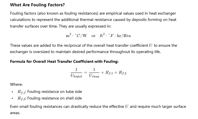
Fouling factors play a critical role in selecting and designing shell and tube heat exchangers because they account for the expected degradation in heat transfer efficiency due to deposit buildup over time. These safety margins, added to the thermal resistance in design calculations, directly influence the required heat transfer area, material choice, cleaning access, and overall exchanger size. Proper fouling allowance ensures long-term performance, reduced downtime, and optimized lifecycle costs in real-world operating conditions.
Despite often being underestimated, fouling is a major contributor to energy waste and unplanned maintenance. In this guide, you’ll learn how fouling factors affect every aspect of exchanger design and how to apply them to maximize performance and reliability.
Fouling factors are essential in the thermal design of shell and tube heat exchangers.Истинный
Fouling adds resistance to heat transfer, which must be accounted for to ensure long-term exchanger performance.
Typical Fouling Factor Values by Industry
Table: Common Fouling Factors for Various Fluids
| Fluid/Medium | Fouling Factor (m²·°C/W) | Comments |
|---|---|---|
| Sea Water (once-through) | 0.00035 | High biological and scaling fouling |
| Treated Boiler Feed Water | 0.0001 | Low fouling potential |
| Crude Oil (dirty service) | 0.0009 – 0.0020 | Sludge, wax, asphaltenes |
| Cooling Tower Water | 0.0002 – 0.00035 | Scaling, algae |
| Process Air (clean) | 0.00005 | Negligible fouling |
| Hydrocarbons (light) | 0.0001 – 0.0002 | Depends on filtration and contaminants |
| Molasses/Sugar Syrup | 0.0010 – 0.0025 | Heavy organic fouling |
Примечание: These values are industry-accepted estimates (TEMA or HEI standards) and must be adjusted based on site-specific experience.
Using lower fouling factors can reduce the size and cost of a heat exchanger.ЛОЖЬ
While smaller fouling allowances reduce initial cost, they compromise reliability and increase the risk of underperformance and frequent cleaning.
How Fouling Affects Heat Exchanger Design
Fouling factors impact multiple design and operational parameters:
- Increased Heat Transfer Area
As fouling reduces ( U ), a larger surface area is required to maintain the desired thermal duty. This leads to longer or wider exchangers, or more passes. Выбор материала
Fouling-prone fluids may require smoother materials (e.g., stainless steel) or non-stick coatings to resist deposition.Cleaning Accessibility
High-fouling applications often dictate use of floating head or U-tube designs for easier cleaning access.Maintenance Frequency
A higher fouling factor implies more frequent cleaning cycles, which must be accounted for in maintenance planning.Operational Efficiency
Neglecting fouling can lead to a 10–40% reduction in efficiency over time, with increased energy consumption.
Types of Fouling and Their Characteristics
Fouling isn’t uniform—it depends on fluid type, operating conditions, and material compatibility.
Table: Major Fouling Types and Mitigation
| Type of Fouling | Описание | Common Fluids | Стратегия смягчения последствий |
|---|---|---|---|
| Scaling | Mineral deposit from hard water | Cooling water, sea water | Water softening, acid cleaning |
| Particulate | Suspended solids accumulation | Slurries, wastewater | Filtration, velocity control |
| Biological (Biofouling) | Algae, bacteria growth | Surface water, sea water | Biocides, UV sterilization |
| Chemical (Polymerization) | Chemical reactions causing films | Crude oil, resins | Inhibitors, temperature control |
| Corrosion Products | Metal oxide build-up | Acidic or corrosive fluids | Material upgrade, corrosion control |
| Freezing Fouling | Ice or solidified hydrocarbon | Low-temperature exchangers | Insulation, flow control |
Real-World Case Study: Fouling Factor Impact
Industry: Refinery
Fluid: Dirty crude oil (tube side), cooling water (shell side)
Initial Design: Fouling factors neglected due to cost constraints
Результат:
- 30% reduction in heat transfer within 6 months
- Frequent shutdowns every 3 months for acid cleaning
- After retrofitting with proper fouling allowances and floating head design, uptime improved by 60%, and cleaning reduced to once per year
This demonstrates that upfront investment in fouling control yields long-term operational savings.
Design Strategies to Handle Fouling
To manage fouling effectively, integrate it into the core design process:
- Apply conservative fouling factors for fluids with unknown or variable composition
- Choose designs with easy access: floating head, removable bundle
- Increase velocity where possible to reduce deposition
- Implement online cleaning systems: backflushing, chemical injection
- Monitor with temperature sensors and pressure drop analysis for predictive maintenance
Floating head exchangers are preferred for high-fouling services due to easy cleanability.Истинный
They allow full access to both shell and tube sides for mechanical cleaning, making them ideal for fouling-prone fluids.
Conclusion: Fouling Factors Are Essential for Reliable Performance
Ignoring fouling factors in shell and tube heat exchanger design is a short-sighted cost-saving tactic that leads to costly operational headaches. When properly considered, these factors enable the design of robust, maintainable, and efficient exchangers that deliver stable performance across their full lifecycle.
Why Is Compliance with Design Codes and Industry Standards Critical in Your Selection Process?
Non-compliance with design codes and industry standards in the selection of a shell and tube heat exchanger can lead to catastrophic failures—equipment rupture, toxic leaks, unplanned downtime, and even legal penalties. In regulated industries like oil & gas, power generation, or pharmaceuticals, operating uncertified equipment could invalidate insurance coverage and regulatory approvals. The cost of non-compliance can be exponential compared to the effort of getting the design right the first time. Ensuring full compliance with recognized standards is not only a matter of engineering best practice—it’s a legal, safety, and economic necessity.
Compliance with design codes and industry standards is critical in the selection of a shell and tube heat exchanger because it ensures mechanical integrity, pressure safety, material compatibility, manufacturing quality, and regulatory acceptance. Standards such as ASME Section VIII, TEMA, API 660, and PED define the minimum design, fabrication, and inspection criteria. Adhering to these codes guarantees that the exchanger can safely operate under its intended temperature, pressure, and chemical conditions while meeting environmental and legal requirements.
If you want your equipment to perform reliably, avoid regulatory violations, and remain insurable, understanding and implementing applicable codes and standards is non-negotiable. In this guide, we’ll explore how these frameworks influence every aspect of exchanger selection and how they impact your project’s success.
All heat exchangers must comply with relevant design codes to be legally installed in most industrial facilities.Истинный
Regulatory authorities require pressure equipment to comply with national or international standards like ASME or PED to ensure public and workplace safety.
Overview of Key Design Codes and Standards
Each region and industry applies specific sets of standards to govern pressure equipment design. For shell and tube heat exchangers, the most common include:
Table: Major Design Codes and Standards
| Стандарт/Кодекс | Issuing Body | Объем | Region/Industry |
|---|---|---|---|
| ASME Section VIII Div. 1 | American Society of Mechanical Engineers | Design and fabrication of pressure vessels | North America, global |
| ТЕМА | Tubular Exchanger Manufacturers Association | Mechanical and dimensional standards for shell and tube heat exchangers | Chemical, petrochemical |
| API 660 | American Petroleum Institute | Standards for shell and tube exchangers in petroleum services | Oil & gas, refineries |
| PED (2014/68/EU) | Евросоюз | Pressure Equipment Directive for CE marking | Европа |
| GOST / TR CU 032/2013 | Eurasian Economic Union | Technical regulations for pressure vessels | Russia, Kazakhstan, etc. |
| CRN | Canadian Registration Number | Design registration required for each province | Canada |
Each of these frameworks includes detailed requirements on:
- Расчетное давление и температура
- Corrosion allowances
- Weld procedures and qualifications
- Nondestructive testing (NDT)
- Hydrostatic and pneumatic testing
- Прослеживаемость материалов
- Inspection and certification
TEMA standards only cover thermal design.ЛОЖЬ
TEMA standards also specify mechanical design, fabrication tolerances, and exchanger construction types (Type A, B, C, etc.).
Why Compliance Is Critical at Every Stage
1. Design Integrity and Safety
Compliant exchangers are engineered to withstand pressure, temperature, and fatigue loading. Non-compliance increases the risk of:
- Pressure vessel explosions
- Weld failures under thermal cycling
- Tube rupture and fluid contamination
- Material fatigue and creep over time
Example:
In 2018, a non-ASME-rated exchanger in a fertilizer plant ruptured due to under-spec wall thickness, leading to ammonia gas release and forced evacuation. This could have been prevented with code-compliant design.
2. Legal and Regulatory Requirements
In many jurisdictions, installing non-compliant heat exchangers is illegal in pressure-rated systems. Failure to comply can result in:
- Plant shutdowns by regulatory inspectors
- Fines or loss of operating licenses
- Insurance policy invalidation
3. Material and Manufacturing Control
Codes like ASME and PED specify minimum requirements for:
- Material selection based on fluid type and temperature
- Certified mill test reports (MTRs)
- Welding procedures (WPS/PQR/WPQ)
- NDT (e.g., RT, UT, PT) for weld integrity
Table: ASME vs. PED Material Certification Requirements
| Требование | ASME Раздел VIII | PED (EN Standards) |
|---|---|---|
| Material Traceability | Required (per UG-93) | Required (EN 10204 3.1/3.2) |
| Impact Testing | Based on MDMT | Mandatory below -10°C |
| Design by Analysis | Optional (Div 1); Required (Div 2) | Required for Category III/IV |
| CE Marking | Not Applicable | Mandatory |
Influence on Equipment Selection and Procurement
When selecting a heat exchanger, code compliance affects:
- Shell and head design type (e.g., TEMA BEM, BEU, AES)
API 660 may require specific TEMA types depending on service. Nozzle sizing and reinforcement
Pressure drop and flow must be within code tolerances.Joint types and gasket selection
Some codes restrict the use of spiral-wound gaskets or demand double sealing.Design life and corrosion allowance
ASME mandates minimum corrosion allowances, which influence material thickness.Documentation and certifications
Including U-stamp (ASME), CE marking (PED), CRN (Canada), and more.
Compliance with PED requires CE marking and notified body approval.Истинный
The Pressure Equipment Directive mandates CE marking for Category I-IV equipment, and approval by an EU Notified Body is required.
Case Study: Compliance Saves the Project
Industry: Нефтехимическая
Location: Europe (PED jurisdiction)
Situation: An EPC contractor sourced low-cost, non-compliant exchangers from a supplier outside the EU. During commissioning, inspectors rejected the equipment due to lack of CE marking and EN 13445 compliance.
Impact:
- Entire exchanger train had to be replaced
- Project delayed by 4 months
- Legal claim filed against supplier
- Insurance refused coverage
Lesson: Short-term savings from non-compliant equipment resulted in a long-term loss of over $2.5 million.
Testing and Certification Requirements
Before delivery, compliant exchangers must undergo:
- Гидростатические испытания: Pressure testing at 1.3x design pressure
- Radiographic or Ultrasonic Testing: For welds as per design category
- Visual Inspection and Dimensional Check: As per TEMA tolerances
- Material Certification Review: For all pressure-retaining components
- Final Inspection by Notified Body (for PED/CE)
Table: Minimum Testing Requirements by Code
| Test Type | ASME | ПЭД | API 660 |
|---|---|---|---|
| Hydrostatic Test | Mandatory | Mandatory | Mandatory |
| Radiographic Weld Testing | Required (Cat B/C) | Required (Cat III/IV) | Required |
| Impact Testing | Below MDMT | Below -10°C | Application-specific |
| Third-Party Inspection | Необязательный | Mandatory (NB required) | Recommended |
Final Thoughts: Code Compliance is Non-Negotiable
Code and standard compliance is the backbone of a safe, functional, and legally operable shell and tube heat exchanger. It’s not just about ticking boxes—it’s about ensuring your equipment is fit for purpose under real-world conditions.
Failing to comply exposes you to technical, legal, and financial risks that far outweigh any upfront cost savings. Instead, compliance should be seen as a performance guarantee and a strategic investment in reliability.
Final Thoughts: Precision Selection Is Key to Performance
The key to successful shell and tube heat exchanger selection lies in harmonizing process demands with technical design flexibility. Whether it’s temperature extremes, corrosive fluids, or strict cleaning requirements, each parameter plays a vital role in shaping your ideal exchanger.
Choosing the right shell and tube heat exchanger is a decision that requires both technical knowledge and application-specific insights. By understanding the criteria outlined above, you can make informed decisions that ensure efficiency, durability, and compliance.
Часто задаваемые вопросы
Q1: How do I determine the right size for a shell and tube heat exchanger?
A1: Sizing a shell and tube heat exchanger involves evaluating flow rates, inlet and outlet temperatures, pressure drops, and required heat transfer rates. Begin by identifying the duty (Q = m·Cp·ΔT), and match that with an exchanger that offers sufficient surface area. You’ll also need to ensure that both shell-side and tube-side fluids maintain acceptable velocities to avoid erosion or fouling. Heat transfer coefficients and thermal conductivity of materials play a vital role in proper sizing.
Q2: Why is material selection important when choosing a shell and tube heat exchanger?
A2: Material selection affects the exchanger’s corrosion resistance, thermal conductivity, durability, and cost. Common materials include stainless steel, carbon steel, copper alloys, and titanium. The correct choice depends on the fluids used, their chemical properties, and operating temperatures. For example, corrosive fluids may require stainless steel or titanium to prevent degradation over time.
Q3: What are the common types of shell and tube configurations, and how do I choose?
A3: Shell and tube heat exchangers come in various configurations, such as fixed tube sheet, U-tube, and floating head designs. Fixed tube sheet exchangers are best for clean fluids and low thermal expansion. U-tube designs handle thermal expansion better and are easier to clean on the shell side. Floating head designs allow for both easy cleaning and thermal expansion, ideal for high-temperature applications. The choice depends on maintenance requirements, temperature variations, and fluid cleanliness.
Q4: How does pressure drop affect heat exchanger performance and selection?
A4: Pressure drop is a crucial parameter because excessive pressure loss reduces pumping efficiency and operational economy. When selecting a heat exchanger, ensure that the design maintains acceptable pressure drops on both shell and tube sides. Lower pressure drop usually means larger exchangers, while tighter spaces require compromises in flow rate or surface area. Engineers must balance heat transfer efficiency and pressure loss for optimal system performance.
Q5: Is it better to use multiple smaller exchangers or a single large one?
A5: Using multiple smaller heat exchangers can improve system redundancy, flexibility, and maintenance scheduling. They allow part of the system to remain operational during maintenance. However, a single large unit might be more cost-effective in terms of initial investment and space requirements. The decision depends on the criticality of the process, available space, budget, and need for operational continuity.
Ссылки
- Shell and Tube Heat Exchangers Explained – The Wermac
- Heat Exchanger Design Handbook – Knovel
- Heat Exchangers Selection Guide – Engineers Edge
- Understanding Heat Exchanger Design – Chemical Processing
- Shell and Tube Heat Exchanger Basics – Thermopedia
- Guide to Heat Exchanger Types – Exchanger Industries
- Choosing the Right Heat Exchanger – Process Heating
- Thermal Design of Shell-and-Tube Heat Exchangers – ScienceDirect
- ASME Heat Exchanger Standards – ASME
- Corrosion in Heat Exchangers – Corrosionpedia