Improper heat transfer design in industrial systems can lead to energy waste, overheating, equipment wear, and even total process failure. Without understanding the operating principle of a shell and tube heat exchanger—one of the most widely used types in process industries—engineers risk specifying the wrong equipment, leading to reduced efficiency and higher maintenance costs. To avoid these problems, it’s essential to grasp the structure, function, and application of shell and tube heat exchangers.
A shell and tube heat exchanger is a device used to transfer heat between two fluids, consisting of a series of tubes (tube bundle) enclosed in a cylindrical shell. One fluid flows through the tubes while the other flows around the tubes within the shell. Heat is transferred across the tube walls without the fluids mixing. This type of exchanger is highly efficient, durable, and suited for high-pressure, high-temperature, and large-capacity applications.

With its robust construction and flexibility, the shell and tube heat exchanger is a cornerstone of thermal systems in oil & gas, chemical, HVAC, and power generation sectors. Understanding how it works and where it performs best is key to optimal process design.
What Is the Basic Structure of a Shell and Tube Heat Exchanger and How Is It Constructed?
Shell and tube heat exchangers are the most widely used thermal transfer devices in industrial applications — from petrochemical plants to power generation facilities. But despite their prevalence, many engineers and plant operators lack a clear understanding of their internal structure and construction. Without this knowledge, it’s easy to miscommunicate with suppliers, misdiagnose performance issues, or select the wrong configuration for your process. Understanding the basic structure and how these units are constructed is essential for proper specification, operation, and maintenance.
The basic structure of a shell and tube heat exchanger consists of a cylindrical shell surrounding a bundle of tubes, through which one fluid flows, while another fluid flows over and around the tubes within the shell. The main components include the shell, tube bundle, tube sheets, baffles, channel heads (or heads), and inlet/outlet nozzles. These exchangers are constructed by assembling the tube bundle inside the shell, welding tube sheets at both ends, and installing baffles to direct shell-side flow. The unit is enclosed with channel heads and tested under pressure to ensure mechanical integrity.
This detailed guide walks you through each major part of a shell and tube heat exchanger — how it’s made, how it works, and how each component plays a role in thermal performance and durability.
Shell and tube heat exchangers consist of a cylindrical shell enclosing a bundle of tubes.True
One fluid flows inside the tubes while the other flows across the outside, enabling indirect heat transfer.
Shell and tube heat exchangers are built in one fixed design for all applications.False
They are highly customizable, with different tube layouts, flow passes, and removable or non-removable bundles depending on the application.
1. Overview of Shell and Tube Construction
The shell and tube heat exchanger is designed for indirect heat exchange between two fluids, separated by solid walls. It’s ideal for high-pressure, high-temperature, and large-scale operations.
Two Main Flow Paths:
- Tube-side fluid: Flows inside the tubes
- Shell-side fluid: Flows around the tubes inside the shell
Common Flow Configurations:
- Counterflow (fluids in opposite directions) – most efficient
- Parallel flow (fluids in same direction)
- Crossflow (mixed)
2. Core Components and Their Functions
A. Shell
- A cylindrical pressure vessel that contains the shell-side fluid
- Usually made of carbon steel or stainless steel
- Supports external nozzles, baffles, and tie rods
| Feature | Specification |
|---|---|
| Shell diameter | 100 mm – 2000+ mm |
| Material | ASTM A516, SS316, Alloy 20 |
| Pressure range | Up to 100+ bar |
B. Tube Bundle
- Consists of hundreds or thousands of tubes, arranged in a pattern
- Held together by tube sheets and support plates
- The tube bundle can be fixed, removable, or floating
| Tube Bundle Type | Use Case |
|---|---|
| Fixed Tube Sheet | Low-cost, clean fluids |
| U-Tube Design | Accommodates thermal expansion |
| Floating Head | Easy cleaning for fouling fluids |
Tube Materials:
- Carbon steel, stainless steel, copper-nickel, titanium, Hastelloy
C. Tubes
- Typically ¾” or 1″ OD (19mm or 25mm)
- Wall thickness defined by BWG or SWG standards
- Surface can be smooth, finned, or corrugated for enhanced transfer
| Tube Layout Patterns | Description |
|---|---|
| Triangular Pitch | High thermal efficiency |
| Square Pitch | Easier cleaning |
| Rotated Square | Intermediate balance |
D. Tube Sheets
- Heavy plates that anchor the tubes at each end
- Tubes are expanded or welded into holes
- Provide sealing between shell and tube sides
| Construction Method | Description |
|---|---|
| Expanded Fit | Tubes rolled into tube sheet holes |
| Seal Welded | For high pressure or critical fluids |
E. Baffles
- Installed transversely inside the shell
- Direct shell-side fluid across tubes to increase turbulence
- Also support the tube bundle and reduce vibration
| Baffle Type | Function |
|---|---|
| Segmental | Most common – improves heat transfer |
| Disc & Doughnut | Low-pressure drop systems |
| No Baffles | Used in laminar or clean applications |
F. Channel Heads (Heads or Bonnet Ends)
- Contain the tube-side inlet and outlet nozzles
- Allow access to tube side for cleaning or inspection
- Can be removable or welded shut, depending on design
| Head Type | Application |
|---|---|
| Channel + Cover | Standard, allows full access |
| Bonnets | Welded or bolted, compact design |
G. Inlet and Outlet Nozzles
- Provide fluid entry and exit points
- Can be located radially or tangentially
- Sizes match pipeline specifications and flanged for easy connection
3. Construction Process (Step-by-Step)
- Design and Simulation:
- Heat duty, flow rates, pressure drops, temperature limits defined
- TEMA/ASME design standards used for stress and thermal analysis
- Tube Sheet Drilling and Machining:
- Holes drilled precisely to match tube layout
- Sheets cut from thick plate (for pressure integrity)
- Tube Bundle Assembly:
- Tubes inserted through baffles and tube sheets
- Tubes expanded or welded into sheet
- Bundle tied with rods and spacers for support
- Shell Fabrication:
- Cylindrical shell rolled and welded from plate
- Nozzles, inspection ports, lifting lugs added
- Baffle mounting rails welded inside
- Bundle Insertion:
- Bundle inserted into shell (or built inside for fixed type)
- For removable units, guide rails and seals installed
- Head Installation:
- Channel heads bolted or welded at both ends
- Gaskets and flanges added
- Testing and Inspection:
- Hydrostatic test at 1.3x design pressure
- NDT tests: Radiography, dye-penetrant, ultrasonic (as per ASME)
- Pressure and leak testing for code compliance
- Painting, Insulation, and Packing:
- External coating applied (epoxy or PU)
- Insulation cladding added for thermal systems
- Lifting lugs and transportation supports fitted
4. Standard Design Codes Used
| Code/Standard | Region | Purpose |
|---|---|---|
| ASME Sec VIII Div. 1 | USA / Global | Design pressure, fabrication, testing |
| TEMA | Global | Mechanical design, maintenance categories |
| PED (2014/68/EU) | EU | Safety and pressure equipment compliance |
| API 660 | Oil & Gas | Specification for shell and tube exchangers |
Real-World Case Study: Shell and Tube Exchanger for Petrochemical Plant
Client: Ethylene oxide processor
Design Duty:
- Fluid 1: Cooling water (shell side)
- Fluid 2: Ethylene glycol (tube side)
- Heat Duty: 1.2 MW
- Pressure: 16 bar shell, 10 bar tube
- Temp: 160°C max
Final Specs:
- Shell: 1000 mm diameter, A516 Gr.70
- Tubes: 800 × SS316L, ¾”, 2-pass U-tube
- Baffles: 20% cut, segmental
- Floating head for full tube bundle removal
Result:
- 98% thermal efficiency
- Easy maintenance every 2 years
- 10+ year service life with no tube failures
Summary: Structure = Performance
A shell and tube heat exchanger is not just a cylinder with tubes — it’s a precision-engineered assembly of components working together to maximize:
- Heat transfer efficiency
- Mechanical integrity
- Cleanability and maintenance access
- Compatibility with pressure, temperature, and media
Understanding how it’s constructed helps you:
- Specify the right unit
- Diagnose issues
- Plan maintenance or retrofits
- Ensure code compliance
Looking for custom-built shell and tube exchangers for your process? Our ASME/TEMA-compliant designs are engineered for performance, durability, and efficiency. Contact us now for 2D/3D models, sizing, and material recommendations.
How Does Heat Transfer Occur in a Shell and Tube Heat Exchanger?
One of the most critical yet misunderstood aspects of shell and tube heat exchangers is the mechanism of heat transfer that happens inside them. Misjudging this process can lead to inefficient system designs, low thermal performance, and equipment oversizing or undersizing. Whether you’re an engineer specifying a system, an operator troubleshooting thermal inefficiency, or a plant designer optimizing layout, understanding how heat moves from one fluid to another inside this exchanger is vital for safe and effective operation.
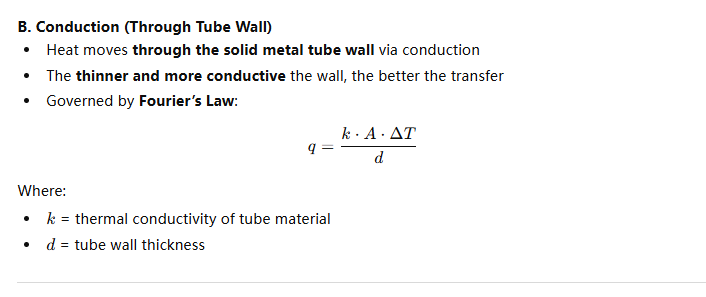
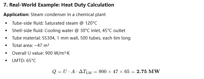
Heat transfer in a shell and tube heat exchanger occurs through the tube walls, where thermal energy is exchanged between two fluids — one flowing inside the tubes (tube-side) and the other flowing outside the tubes within the shell (shell-side). The process involves three stages: convection from the hot fluid to the tube wall, conduction through the tube wall, and convection from the tube wall to the cooler fluid. The efficiency depends on flow arrangement, fluid properties, turbulence, and surface area.
This detailed guide breaks down the thermodynamic and physical processes behind heat exchange in shell and tube systems — with clear diagrams, technical explanations, and performance insights to help you optimize every stage of thermal interaction.
Heat transfer in shell and tube heat exchangers takes place through conduction and convection.True
Heat is conducted through the tube wall and convected from one fluid to the other across the metal barrier.
The fluids in a shell and tube heat exchanger mix during operation to transfer heat efficiently.False
Fluids remain completely separate — heat is transferred through the solid tube wall, preventing cross-contamination.
![]()
C. Convection (from Tube Wall to Cold Fluid)
- Finally, heat is released into the cooler fluid on the shell side
- Baffles increase turbulence and contact time
- Convective transfer occurs from tube outer surface to shell-side fluid
2. Flow Arrangements and Their Effect on Heat Transfer
| Type of Flow | Description | Heat Transfer Efficiency |
|---|---|---|
| Counterflow | Fluids move in opposite directions | ✅ Highest (max ΔT) |
| Parallel Flow | Fluids flow in same direction | ⚠️ Lower |
| Crossflow | Shell fluid flows perpendicular to tube fluid | ⚠️ Medium |
| Multipass Flow | Fluids change direction via baffles or headers | ✅ Efficient + compact |
Design Tip: Use counterflow wherever possible to maximize temperature differential.
![]()
4. Shell-Side vs. Tube-Side Heat Transfer
| Feature | Shell Side | Tube Side |
|---|---|---|
| Flow direction | Around the outside of tubes | Inside the tubes |
| Common fluids | Cooling water, steam | Process fluid, viscous or corrosive |
| Velocity | Lower than tube side | Typically higher |
| Cleaning access | Harder (fixed type) | Easier (via channel head) |
| Heat transfer coefficient | Lower without turbulence | Higher with good flow control |
Baffles on the shell side help increase turbulence, improving shell-side coefficient.
5. Thermal Resistance Layers in Heat Transfer
The complete thermal path has several resistance layers:
| Layer | Role in Heat Transfer |
|---|---|
| Tube-side fluid film | Resistance from fluid to wall |
| Tube metal wall | Conduction through solid |
| Shell-side fluid film | Resistance from wall to fluid |
| Fouling (if present) | Reduces effective conductivity |
Goal: Minimize resistance in all layers to enhance heat transfer.
6. Factors That Affect Heat Transfer Efficiency
| Factor | Impact |
|---|---|
| Tube material | Higher conductivity = better transfer |
| Tube wall thickness | Thicker wall = more resistance |
| Flow velocity | Higher velocity = turbulent = better |
| Fouling deposits | Insulate surface, reduce efficiency |
| Baffle design | Directs flow across tubes |
| Temperature difference | Greater ΔT = higher transfer rate |
8. Enhancing Heat Transfer Performance
| Strategy | How It Helps |
|---|---|
| Use finned tubes | Increases effective area |
| Opt for multi-pass flow | Improves turbulence |
| Choose higher U materials | Like copper or alloy |
| Regular cleaning | Removes fouling from surfaces |
| Implement variable flow control | Keeps optimal turbulence |
Summary: Understanding the Thermal Path
Heat transfer in a shell and tube heat exchanger involves multiple resistances working in series:
- Convective film on the hot side
- Tube wall conduction
- Convective film on the cold side
Efficiency depends on turbulence, temperature difference, material conductivity, and clean surfaces. Managing all of these factors — especially through smart design and maintenance — is the key to optimizing performance.
What Are the Different Flow Configurations in Shell and Tube Heat Exchangers?
When designing or selecting a shell and tube heat exchanger, one of the most critical decisions is choosing the right flow configuration. This decision impacts not just heat transfer performance, but also pressure drop, footprint, mechanical stress, and maintenance complexity. A mismatch between flow pattern and process conditions can result in inefficient heat transfer, excessive pressure loss, or even thermal shock failure. By understanding the different flow configurations, engineers and plant designers can optimize thermal efficiency, ensure safe operation, and improve equipment longevity.
The main flow configurations in shell and tube heat exchangers include counterflow, parallel flow, crossflow, and multipass arrangements. Each configuration refers to the relative direction and distribution of fluids inside the shell and tube sides. Counterflow provides the highest heat transfer efficiency due to maximum temperature gradients, while multipass designs enhance turbulence. The optimal configuration depends on the required thermal performance, pressure drop constraints, and maintenance access.
This in-depth guide explains each configuration, how it works, when to use it, and its pros and cons — complete with engineering diagrams and performance tables.
The flow configuration in a shell and tube heat exchanger significantly impacts its thermal performance.True
Flow direction and pass arrangement influence temperature gradients, pressure drop, and heat transfer coefficients.
All shell and tube exchangers use a single fixed flow pattern for all applications.False
Exchangers can be configured for counterflow, parallel, crossflow, or multipass flow depending on process requirements.
1. Counterflow Configuration
How It Works:
- The hot and cold fluids flow in opposite directions
- Usually the tube-side fluid enters from one end, while the shell-side fluid enters from the opposite
Diagram:
Tube-side:    ─────────►
Shell-side: ◄──────────
Key Benefits:
- Highest thermal efficiency
- Maintains maximum temperature gradient throughout length
- Ideal for large temperature differences
Best Used When:
- High heat recovery is required
- Compact design is preferred
- High-pressure tube-side applications
| Parameter | Value |
|---|---|
| Heat Efficiency | ✅ Highest |
| Pressure Drop | ⚠️ Moderate–High |
| Complexity | ⚠️ Requires proper design |
2. Parallel Flow Configuration
How It Works:
- Both fluids enter from the same end and flow in the same direction
Diagram:
Tube-side:    ─────────►
Shell-side:   ─────────►
Key Benefits:
- Simple layout
- Lower thermal stress
Limitations:
- Lower temperature differential at outlet
- Less efficient than counterflow
Best Used When:
- Inlet temperatures are close
- Short thermal paths are acceptable
| Parameter | Value |
|---|---|
| Heat Efficiency | ⚠️ Low |
| Pressure Drop | ✅ Low |
| Complexity | ✅ Simple |
3. Crossflow Configuration
How It Works:
- One fluid flows perpendicular to the other
- Often used in air-cooled exchangers but applicable in shell and tube with specific baffle layouts
Diagram:
Tube-side:    ─────────►
Shell-side:   ↑↑↑↑↑↑↑↑↑↑↑
Key Benefits:
- Balanced thermal performance
- Can be compact
Limitations:
- Uneven temperature distribution
- Complex design to avoid dead zones
Best Used When:
- One fluid is a gas or vapor
- Moderate heat transfer is acceptable
| Parameter | Value |
|---|---|
| Heat Efficiency | ⚠️ Medium |
| Pressure Drop | ✅ Moderate |
| Complexity | ⚠️ Higher baffle design |
4. Multipass (Tube or Shell) Configuration
How It Works:
- Fluids pass through the exchanger multiple times
- Tubes are divided into passes using partitioned channel heads
- Shell side can also be divided with longitudinal baffles
Diagram (2-pass tube):
Pass 1: ─────────►
U-turn
Pass 2: ◄─────────
Key Benefits:
- Increases turbulence and heat transfer coefficient
- More compact for the same duty
- Balances flow rate and temperature approach
Limitations:
- Higher pressure drop
- More complex fabrication and inspection
Best Used When:
- High viscosity or fouling fluids
- Limited space but high duty needed
| Pass Configuration | Description |
|---|---|
| 2-Pass Tube Side | Fluid reverses once, better thermal mixing |
| 4-Pass Tube Side | Common in high-efficiency designs |
| Split Shell Flow | Reduces flow maldistribution |
5. Split Flow and Divided-Flow Shell
Specialized Designs:
- Split flow directs fluid into two opposite shell sides
- Divided-flow allows simultaneous forward and reverse shell flows
| Type | Benefit |
|---|---|
| Split Flow Shell | Lower pressure drop, higher flow |
| Divided-Flow Shell | Better temperature control |
| Helical Baffle Flow | Improves turbulence, lowers vibration |
6. Comparison Table of Flow Configurations
| Configuration | Heat Transfer | Pressure Drop | Mechanical Stress | Application Suitability |
|---|---|---|---|---|
| Counterflow | ✅ Excellent | ⚠️ Moderate | ⚠️ High (if extreme ΔT) | Best for high-efficiency needs |
| Parallel Flow | ⚠️ Poor | ✅ Low | ✅ Low | Low thermal duty applications |
| Crossflow | ⚠️ Medium | ✅ Medium | ✅ Low | Gas-liquid, air-cooled |
| Multipass | ✅ Good | ⚠️ High | ⚠️ Moderate | High-duty, high-viscosity |
| Split/Divided | ✅ Advanced | ✅ Optimized | ⚠️ Complex | Specialty processes |
Real-World Case Study: Selecting Flow Pattern for Reactor Cooling
Process: Chemical reactor loop
Fluid 1 (tube): High-pressure oil at 180°C
Fluid 2 (shell): Cooling water at 30°C
Thermal duty: 1.8 MW
Flow constraint: Limited cooling water flow rate
Solution:
- Selected counterflow with 2-pass tube side
- Baffles: Segmental with 25% cut
- Enhanced turbulence → reduced exchanger length by 22%
- Achieved outlet temp: <50°C in water, meeting spec
Summary: Match Flow to Function
Flow configuration in a shell and tube heat exchanger is not a one-size-fits-all decision. It defines the temperature profile, thermal efficiency, and operational viability of your system.
- Use counterflow for maximum heat recovery
- Choose multipass when compactness and high duty are priorities
- Consider parallel or crossflow for simpler or gas-based applications
- Always balance pressure drop, material stress, and cleanability
What Are the Advantages and Disadvantages of Shell and Tube Heat Exchangers?
Shell and tube heat exchangers are among the most widely used thermal exchange systems in industrial processes — from chemical production to oil refining, HVAC to food processing. But as robust and adaptable as they are, they are not a perfect fit for every situation. If you’re choosing a heat exchanger for a new system or evaluating existing performance, you need to weigh the advantages and disadvantages of this design. Misjudging its suitability can lead to overengineering, poor heat transfer, costly maintenance, or worse, catastrophic failure in extreme conditions.
Shell and tube heat exchangers offer high-pressure and temperature resistance, flexibility in design, ease of cleaning, and robust performance, making them ideal for industrial applications. However, they also present disadvantages such as large size, susceptibility to fouling, higher pressure drops in multipass systems, and more complex maintenance for certain configurations. Selecting the right type requires balancing performance demands, space constraints, maintenance expectations, and fluid characteristics.
This comprehensive analysis breaks down the key pros and cons of shell and tube heat exchangers — based on mechanical design, thermodynamics, process compatibility, and lifecycle cost — to help you make an informed decision.
Shell and tube heat exchangers are highly durable and suitable for high-pressure and high-temperature applications.True
Their construction allows them to withstand extreme process conditions, making them standard in many industrial settings.
Shell and tube heat exchangers are compact and always easy to clean.False
While robust, they are generally bulky and some designs (like fixed tube sheets) can be difficult to clean and maintain.
1. Advantages of Shell and Tube Heat Exchangers
✅ A. High Pressure and Temperature Capability
| Parameter | Typical Value |
|---|---|
| Pressure Rating | Up to 100 bar or more |
| Temperature Range | -50°C to 800°C+ |
| Applicable Codes | ASME Section VIII, TEMA, PED |
- Can handle steam, high-pressure fluids, and thermally aggressive services
- Suitable for superheated fluids, thermal oil loops, or high-pressure refrigerants
✅ B. Design Flexibility and Customization
| Custom Feature | Options Available |
|---|---|
| Tube configurations | U-tube, straight tube, floating head |
| Flow configurations | 1–2–4 pass, split-shell, crossflow |
| Material options | CS, SS, copper, Inconel, titanium |
| Removability | Fixed bundle, removable, floating |
- Easily tailored to different media types, layouts, and plant conditions
- Configurable for cleaning, expansion, and process performance
✅ C. Wide Range of Materials
- Carbon steel for low-cost and neutral fluids
- Stainless steel for sanitary, corrosive, or food-grade applications
- Titanium, Hastelloy, Inconel for highly corrosive or saline environments
✅ D. Maintenance and Cleaning (in Right Designs)
| Feature | Benefit |
|---|---|
| Removable bundle | Allows mechanical cleaning of tubes |
| Channel head | Access to tube side for inspection |
| Floating head | Disassembly without removing the shell |
Design Note: Easy cleaning depends on configuration. U-tube is harder to clean than straight-tube.
✅ E. Multi-Fluid and Multi-Pass Capability
- Tube passes and shell baffles can be configured to meet:
- High heat duty
- Low or high flow rates
- Variable temperature gradients
- Supports cross-contamination-free heat transfer in multi-fluid systems
✅ F. Long Lifespan and Field Proven
- Lifespan: 15–30+ years with proper material and design
- Used in power plants, refineries, marine systems, and pharmaceuticals
| Lifecycle Characteristic | Shell and Tube Exchanger |
|---|---|
| Longevity | ✅ Excellent (>20 years typical) |
| Reliability | ✅ Proven in critical systems |
| Code Compliance | ✅ ASME, TEMA, PED certified |
2. Disadvantages of Shell and Tube Heat Exchangers
⚠️ A. Large Physical Size and Weight
| Example Comparison | Shell & Tube | Plate Heat Exchanger |
|---|---|---|
| Heat duty (1 MW) | ~4–6 m length | ~1.5–2 m² footprint |
| Weight (with fluids) | 800–2000+ kg | 200–400 kg |
- Large size requires more floor space, support structure, and lifting equipment
- Challenging to install in tight mechanical rooms or offshore platforms
⚠️ B. Potential for Fouling and Scaling
- Tube surfaces are susceptible to mineral scaling or sludge from poor-quality fluids
- Fouling reduces thermal efficiency and increases cleaning frequency
| Fluid Type | Fouling Risk |
|---|---|
| Cooling water | ✅ High |
| Steam (wet) | ⚠️ Medium |
| Process slurry | ✅ Very High |
Preventive Measures:
- Use strainers, filters
- Add chemical treatment
- Design for turbulence and easy access
⚠️ C. High Pressure Drop in Complex Configurations
- Multi-pass or high-tube-count designs increase frictional resistance
- Improper design can choke low-pressure systems
| Design Feature | Effect on Pressure Drop |
|---|---|
| More baffles | ✅ Higher turbulence = higher drop |
| Small tube diameters | ✅ More resistance |
| High fluid viscosity | ✅ Slower velocity = more loss |
⚠️ D. Maintenance Challenges (in Some Designs)
| Tube Bundle Type | Maintenance Accessibility |
|---|---|
| Fixed Tube Sheet | ❌ Hard to access shell side |
| U-Tube | ⚠️ Harder to clean inside |
| Floating Head | ✅ Full removal possible |
- Tube leaks require cutting, pulling, and re-rolling or welding
- Large bundles require heavy lifting equipment
⚠️ E. Higher Initial Cost Than Compact Units
- Compared to plate or spiral heat exchangers, initial CAPEX is higher
- Custom materials (Inconel, titanium) further increase price
- However, this is offset by longer lifecycle in most industrial cases
3. Quick Comparison Table: Shell and Tube vs Other Heat Exchangers
| Feature | Shell & Tube | Plate Type | Air-Cooled |
|---|---|---|---|
| Heat Transfer Area / m² | ✅ High | ✅ Higher per volume | ⚠️ Limited |
| Space Requirement | ⚠️ High | ✅ Compact | ✅ Variable |
| Pressure/Temp Capability | ✅ Excellent | ⚠️ Limited | ✅ Good |
| Fouling Resistance | ⚠️ Medium | ❌ Poor | ✅ Good (outside) |
| Maintenance Accessibility | ✅ Good (removable) | ✅ Excellent | ✅ Easy |
| Typical Use Cases | Industry, Power | HVAC, Pharma | Remote gas/oil |
Real-World Use Case: Why Shell & Tube Was Chosen Over Compact Design
Industry: Petrochemical plant
Fluid: Crude oil and high-pressure steam
Challenge:
- High pressure (20 bar)
- High duty (3.5 MW)
- Susceptible to fouling
- No margin for cross-contamination
Outcome:
- Shell and tube unit with 316L tubes, floating head design
- Maintained >95% heat efficiency with biannual cleaning
- Operating >10 years with no unplanned downtime
Summary: Are Shell and Tube Exchangers Right for You?
Shell and tube heat exchangers offer unmatched durability, design flexibility, and suitability for high-pressure and high-temperature applications. However, they come with trade-offs in size, fouling susceptibility, and maintenance complexity in some cases.
✅ Choose shell and tube exchangers when:
- You have high heat duties and harsh fluids
- Pressure and temperature conditions are demanding
- Cleanability or durability is a priority
- Custom design is needed for unique layouts
⚠️ Consider alternatives (plate, spiral, air-cooled) when:
- Space is limited
- Fluids are clean, low-viscosity, and at low pressure
- Frequent maintenance is not feasible
In What Industrial Applications Are Shell and Tube Heat Exchangers Most Commonly Used?
Shell and tube heat exchangers are the backbone of industrial heat transfer systems — used in almost every major sector involving thermal energy exchange. Whether cooling crude oil, condensing steam, sterilizing dairy, or recovering waste heat from gas turbines, this exchanger type provides the durability, pressure tolerance, and flexibility needed in tough environments. Failing to select the right configuration for the correct industry use case can lead to scaling, corrosion, inefficiency, or costly shutdowns. So understanding where and why these heat exchangers are most commonly used is essential for process engineers, designers, procurement teams, and maintenance planners.
Shell and tube heat exchangers are most commonly used in industrial applications such as oil and gas refining, power generation, chemical processing, HVAC systems, food and beverage sterilization, pharmaceuticals, marine systems, pulp and paper, and wastewater treatment. Their popularity stems from their ability to withstand high pressures and temperatures, handle a wide range of fluids, and be customized for dirty, corrosive, or hazardous service conditions.
Let’s explore the top industries where shell and tube exchangers dominate, why they are preferred in those sectors, and real examples of how they’re applied.
Shell and tube heat exchangers are widely used across diverse industries due to their durability and adaptability.True
Their design supports a range of fluids, pressures, temperatures, and cleaning methods, making them versatile across sectors.
Shell and tube heat exchangers are only suitable for clean water or air-cooling systems.False
They are ideal for challenging fluids, including crude oil, steam, corrosive chemicals, and process slurries.
1. Oil and Gas / Petrochemical Industries
Applications:
- Crude oil preheaters
- Reboilers in distillation columns
- Condensers and coolers for refinery gases
- Gas dehydration systems
Why Shell & Tube is Ideal:
- Withstands high temperatures (up to 600°C)
- Handles high pressures (up to 100 bar or more)
- Resistant to fouling with floating or removable bundles
- Customizable metallurgy (e.g., 316L, Hastelloy, Incoloy)
| Equipment Zone | Use of Heat Exchanger |
|---|---|
| Atmospheric distillation | Preheat feed, recover product vapors |
| Hydrocracking | Cool reactor effluent |
| Amine treating unit | Regenerator and cooler duties |
2. Power Generation (Thermal and Nuclear)
Applications:
- Steam condensers (turbine exhaust)
- Feedwater heaters (low and high pressure)
- Lube oil coolers
- Generator hydrogen coolers
Why Shell & Tube is Ideal:
- Handles large temperature gradients
- Supports vacuum and sub-atmospheric pressure operations
- Designed to ASME Section III for nuclear service
- Excellent for closed-loop cooling systems
| Process Fluid | Role in Heat Transfer System |
|---|---|
| Condensate return | Heat recovery |
| Boiler blowdown | Energy extraction before disposal |
| Hydrogen cooling | Maintains generator operating temp |
3. Chemical and Process Industries
Applications:
- Reactant preheaters
- Cooling of exothermic reaction products
- Solvent recovery and condensation
- Reboilers and condensers in fractionation units
Why Shell & Tube is Ideal:
- High chemical resistance with lined or alloy tubes
- Can manage high viscosity, corrosive fluids
- Easily configured for multi-pass and high-duty applications
- Accommodates both liquid-liquid and gas-liquid systems
| Example Process Unit | Heat Exchanger Role |
|---|---|
| Chlor-alkali production | Brine cooler, chlorine condenser |
| Polymerization | Product cooler, monomer heater |
| Fertilizer plant (urea) | Ammonia and CO₂ heat management |
4. Food and Beverage Industry
Applications:
- Pasteurizers for milk, juice, beer
- Product heating for canning lines
- CIP (clean-in-place) water heating and recovery
- Chocolate and syrup cooling
Why Shell & Tube is Ideal:
- Hygienic designs available (316L SS, sanitary heads)
- Can be electropolished and CIP compliant
- Durable in batch or continuous operation
- Withstands thermal cycling common in food systems
| Product Type | Shell and Tube Role |
|---|---|
| Dairy (milk/yogurt) | Pasteurization, cream separation |
| Brewing | Wort coolers, yeast jacket heaters |
| Tomato processing | Preheating, steam condensing |
5. Pharmaceutical and Biotech
Applications:
- WFI (Water for Injection) heaters
- Steam sterilization systems (SIP)
- Bioreactor jacket heating
- API cooling and crystallization
Why Shell & Tube is Ideal:
- Fully drainable, crevice-free tube designs
- 316L SS with ASME BPE or cGMP compliance
- Sanitary tri-clamp or orbital weld connections
- Can be electropolished to <0.4 µm Ra
| Application Zone | Exchanger Function |
|---|---|
| Fermentation | Jacket temperature control |
| Purified water systems | Preheat before UV treatment |
| Clean steam generation | Condensing blowdown or recovery |
6. Marine and Shipbuilding
Applications:
- Engine jacket water coolers
- Central lube oil cooling
- Freshwater generators
- Fuel oil heating
Why Shell & Tube is Ideal:
- Compact and rugged design
- Compatible with seawater cooling (CuNi, titanium tubes)
- Built to marine classification codes (DNV, ABS, LR)
- Easy to disassemble and clean on board
| Equipment Area | Shell and Tube Role |
|---|---|
| Diesel engines | Heat oil and coolant loops |
| Desalination plant | Condense steam into potable water |
| Shaft bearing systems | Circulating oil temperature control |
7. HVAC and District Energy
Applications:
- Chilled water cooling
- Hot water loop heating
- Refrigerant condensers and evaporators
- Thermal energy storage exchangers
Why Shell & Tube is Ideal:
- Supports large building loads or industrial chillers
- Accommodates low pressure drops and high flow rates
- Designed for long-term reliability in non-corrosive systems
- Often paired with plate heat exchangers for energy separation
| System Type | Function |
|---|---|
| Data centers | Liquid cooling for servers |
| Industrial warehouses | Chilled water heat exchange |
| District heating loops | Isolate and transfer between circuits |
8. Pulp and Paper Industry
Applications:
- Black liquor heating
- Bleach plant effluent cooling
- Steam condensers in drying sections
- Chemical recovery systems
Why Shell & Tube is Ideal:
- Resists fouling with removable bundles
- Withstands corrosive bleach agents with alloy tubes
- Supports high solids content media
- Custom tube layouts for dirty or fibrous fluids
| Process Stage | Exchanger Role |
|---|---|
| Digester | Recovers and recycles cooking energy |
| Evaporation | Concentrates black liquor |
| Paper drying | Condensate recovery and reuse |
9. Water and Wastewater Treatment
Applications:
- Sludge and digestate heat recovery
- Effluent cooling before discharge
- Reverse osmosis brine cooling
- Biogas condensation
Why Shell & Tube is Ideal:
- Withstands fouling fluids with floating head designs
- Can be rubber-lined or FRP-coated for aggressive chemicals
- Accepts high solids and bio-organic content
- Supports continuous or batch systems
| Water Treatment Area | Heat Transfer Duty |
|---|---|
| Anaerobic digesters | Heat sludge to promote digestion |
| RO desalination plants | Recover and reuse waste heat |
| Industrial wastewater | Lower temperature before discharge |
Summary Table: Industries Using Shell and Tube Exchangers
| Industry Sector | Typical Fluids Handled | Heat Exchanger Role |
|---|---|---|
| Oil & Gas | Crude, hydrocarbons, amine | Preheating, condensing, cooling |
| Power Generation | Steam, feedwater, hydrogen | Condensing, feed heating |
| Chemical Processing | Acids, solvents, polymer slurries | Reaction heat control, recovery |
| Food & Beverage | Milk, beer, juice, sauces | Pasteurizing, cooling, CIP |
| Pharmaceuticals | WFI, steam, sterile fluids | Heating, SIP/CIP, crystallization |
| Marine | Seawater, engine oil | Cooling loops, potable water gen |
| HVAC | Chilled/hot water, refrigerants | Load transfer, energy recovery |
| Pulp & Paper | Black liquor, steam, condensate | Energy recovery, chemical handling |
| Water Treatment | Sludge, brine, effluent | Heating, cooling, recovery |
Final Thoughts: A Trusted Workhorse Across Industries
Shell and tube heat exchangers are not just industrial commodities — they are mission-critical components that define energy efficiency, safety, and reliability across dozens of industries. Their ability to handle tough fluids, high pressure and temperature, and specialty process requirements makes them irreplaceable in large-scale operations.
Whether you’re refining oil, sterilizing milk, condensing steam, or cooling seawater, a properly designed shell and tube exchanger will deliver decades of performance.
By mastering these foundational insights, you can better select, operate, and maintain this critical piece of thermal equipment, ensuring reliable and cost-effective performance in your operation.
FAQ
Q1: What is a shell and tube heat exchanger?
A1: A shell and tube heat exchanger is a type of heat transfer device commonly used in industrial settings. It consists of a large cylindrical shell (outer vessel) that surrounds a bundle of tubes. One fluid flows through the tubes while another flows around the tubes inside the shell. The heat is exchanged between the two fluids without them mixing, making it ideal for processes that require thermal transfer while keeping fluids separate.
Q2: How does a shell and tube heat exchanger work?
A2: Here’s how it operates:
– One fluid enters the tube side and flows through the bundle of tubes.
– The other fluid flows through the shell side, outside the tubes but inside the shell.
– Heat is transferred across the tube walls from the hot fluid to the cold one.
– The design can be configured for counterflow, parallel flow, or crossflow, depending on the thermal performance required.
Baffles are often used inside the shell to direct flow and increase turbulence, which improves heat transfer efficiency.
Q3: What are the main components of a shell and tube heat exchanger?
A3: Key components include:
– Shell: The outer pressure vessel.
– Tube Bundle: A set of tubes arranged inside the shell.
– Tube Sheets: Plates that hold the tubes in position at both ends.
– Baffles: Direct the shell-side fluid flow and support tubes.
– End Caps/Heads: Direct fluid into and out of the tubes.
– Nozzles: Entry and exit points for fluids.
Each component plays a vital role in maintaining pressure, optimizing heat exchange, and ensuring system reliability.
Q4: What are the advantages of using a shell and tube heat exchanger?
A4: The benefits include:
– High pressure and temperature tolerance
– Customizable design for various applications
– Scalability for large heat transfer requirements
– Ease of maintenance through removable tube bundles
– Durability in harsh industrial environments
These characteristics make them ideal for industries like oil refining, power generation, petrochemical processing, and HVAC systems.
Q5: Where are shell and tube heat exchangers commonly used?
A5: Common applications include:
– Petrochemical plants
– Oil refineries
– Power plants
– HVAC systems
– Pharmaceutical manufacturing
– Food and beverage processing
They are preferred where high heat loads, high pressures, or aggressive chemicals are involved.
References
- Shell and Tube Heat Exchangers Explained – Thermopedia
- Heat Exchangers: Design and Operation – Chemical Engineering
- Shell & Tube Heat Exchanger Basics – Alfa Laval
- How Shell and Tube Heat Exchangers Work – API Heat Transfer
- Baffles in Heat Exchangers – Process Heating
- Shell and Tube Design Standards – ASME
- Heat Exchanger Fundamentals – Engineering Toolbox
- Shell and Tube vs Plate Heat Exchangers – Graham Corporation
- Maintenance of Heat Exchangers – Chemical Processing
- Applications of Heat Exchangers – Process Industry Forum