
Submitting an incomplete request for a custom pressure vessel quote doesn’t just slow things down — it triggers a chain of back-and-forth emails that can stretch a 5-day turnaround into three weeks, forces fabricators to make conservative assumptions that inflate pricing by 15–30%, and occasionally results in a vessel built to the wrong design basis entirely. On EPC projects with hard-schedule milestones, that gap between what procurement sends and what engineering actually needs is where contingency budgets quietly disappear.
Before requesting a custom pressure vessel quote, you need to supply: design pressure and temperature (including full-vacuum or upset conditions), vessel function and fluid service (composition, phase, toxicity, H2S content), applicable design code (ASME VIII Div.1/Div.2, PED, GB 150, etc.), material requirements or restrictions, required certifications and third-party inspection scope, nozzle and connection schedule, site and delivery constraints, and any applicable P&ID or process datasheet. Together these define the fabricator’s scope with enough precision to price accurately.
Most procurement teams believe they are sending enough information. They attach a one-page spec sheet, name the operating pressure and temperature, and expect a firm number within the week. What actually happens at the fabricator’s desk is more instructive — and understanding exactly what gets assumed, padded, or deferred when that data is missing explains why the quote you receive rarely resembles the price you eventually pay.
Process Conditions and Operating Parameters: The Non-Negotiable Starting Point
Every pressure vessel design begins with a single question: what is the fluid doing inside, under what conditions, and what happens when something goes wrong? Without credible answers to that question, a fabricator is guessing — and a quote built on guesses either leaves margin money on the table or, more likely, triggers a costly revision cycle after the first engineering review.
Design Pressure vs. Operating Pressure — Why Both Numbers Must Appear
These two values are not interchangeable, and submitting only one is one of the most common gaps in EPC inquiry packages. Operating pressure is the steady-state working pressure the process actually runs at. Design pressure is the envelope the vessel must be rated to withstand, including normal process fluctuations and the actuation setpoint of the pressure relief device.
The standard rule of thumb: design pressure should be the higher of operating pressure plus 10%, or operating pressure plus 30 psi — whichever gives the larger value. For a vessel running at 150 psi, that means a 165 psi design pressure minimum. For a vessel at 20 psi, the 30 psi adder governs, landing you at 50 psi design pressure. ASME Section VIII Div. 1 covers custom vessels from 15 psi up to roughly 3,000 psi in standard configurations; where that upper limit matters is in wall thickness calculations, shell course count, and whether you’re still inside Div. 1 territory or need to step up to Div. 2.
Design pressure and operating pressure are the same value on most vesselsFalse
Design pressure must include a margin above operating pressure to account for process surges and relief valve setpoints; using operating pressure alone leads to an undersized vessel that cannot legally be code-stamped without relief device coordination.
Stating only one figure forces the fabricator to assume the other — and conservative assumptions mean heavier wall thickness, higher material cost, and a quote that looks uncompetitive against a bidder who asked the right question.
Design Temperature, Upset Excursions, and MDMT
Temperature has a ceiling and a floor, both of which matter. Design temperature is the maximum metal temperature the shell, heads, and nozzles will reach in any credible operating scenario — including startup, regeneration cycles, or CIP conditions, not just steady-state. Steam-traced vessels, reactors with exothermic potential, and reboilers routinely see short-duration excursions 20–40°C above normal operation. If those peaks aren’t disclosed, the fabricator selects material allowable stress at the wrong point on the curve.
The floor is equally important. Minimum Design Metal Temperature (MDMT) governs impact testing requirements. Carbon steel vessels operating below −20°F (−29°C) — or below certain thickness and pressure thresholds even at warmer temperatures — require Charpy impact testing per UCS-66. Failing to flag cold-service or cryogenic duty at the inquiry stage means the quote arrives without impact test cost included, then the schedule slips when the mill cert comes back and the buyer discovers the plate doesn’t qualify.
Full Fluid Inventory: Composition, Phase, and Physical Properties
A description like “process gas” or “mixed hydrocarbons” is insufficient. The fabricator’s materials engineer needs fluid composition — component breakdown, molecular weight range, and any trace contaminants. H₂S content triggers NACE MR0175/ISO 15156 compliance, which mandates hardness limits at or below 22 HRC for carbon steel weldments. Chloride concentration affects stainless steel selection. CO₂ partial pressure drives corrosion allowance decisions. These are not conservative assumptions a fabricator can make without data; they require explicit values from the process engineer.
Phase matters too. A single-phase liquid vessel behaves very differently from a two-phase separator under slug flow conditions. For two-phase or vapor service, provide vapor fraction, density at operating conditions, and viscosity — all at operating temperature and pressure, not ambient. Flow rate or throughput establishes residence time for separators or reaction vessels and directly sets the shell diameter.
Cyclic and Transient Service
Pressure cycling frequency is often left off inquiry packages entirely. A vessel that pressurizes and depressurizes more than roughly 1,000 cycles over its design life crosses into fatigue territory under Appendix 5 of ASME VIII Div. 2 rules. Thermal shock — rapid quenching from hot fluid injection or emergency cooling — can produce stress ranges that dwarf static design loads. If your process involves batch reactors, pressure swing adsorption, or frequent online/offline switching, state the expected cycle count and temperature swing explicitly. Ignoring this at the RFQ stage produces a vessel designed for static service that fails prematurely under real operating conditions.
Lethal, Toxic, and Flammable Service Designations
ASME VIII UW-2 defines lethal service as exposure to substances that are dangerous to human life in small concentrations. Vessels in lethal service require full radiographic examination (RT) of all butt welds, regardless of whether RT would otherwise be mandatory at the selected joint efficiency. This has direct cost and schedule implications — radiography adds 8–20% to fabrication cost in typical cases, depending on vessel complexity and weld joint count. Toxic or flammable service designation under your local jurisdictional authority may also require a higher post-weld heat treatment (PWHT) scope, third-party inspection witness points, and additional documentation packages.
If the fluid is on the toxic or extremely hazardous substance list under your operating jurisdiction, state it on the datasheet. Fabricators who discover this late will reprice, reschedule, and may flag it as a contract scope change. Stating it upfront keeps the bid clean and the timeline honest.
Geometry, Orientation, and Dimensional Constraints Vendors Must Know
A fabricator who receives only a design pressure and temperature has maybe 20% of what they need to build a vessel. The physical envelope — diameter, length, orientation, nozzle layout, support configuration — drives material take-off, plate rolling schedules, head forming lead times, lifting fixture design, and the truck or barge logistics that get the vessel to your site. Miss any of these, and the quote you receive either carries a heavy contingency buffer or comes back with a clarification list that costs you two weeks.
Inside Diameter, Volume Target, and Head Geometry
Start with the process requirement: is the constraint a minimum working volume in liters or gallons, a specific inside diameter set by internals (mist eliminator diameter, tray spacing, packing section), or a maximum outside diameter driven by structural bay width? These are not interchangeable starting points. Specify which one governs and let the fabricator derive the others.
Head type has real cost and pressure-rating consequences. Ellipsoidal 2:1 heads — the workhorse of most ASME Section VIII Div.1 vessels in the 15 psi to 3,000 psi range — are stock items in common diameters and add predictable lead time. Hemispherical heads carry thinner required wall thickness for the same pressure but are slower and more expensive to form; they make sense above roughly 300 psi on larger diameters where the shell savings justify the head cost. Flat heads are cheap to cut but require heavy wall or bolting flanges and are typically limited to small, low-pressure applications. Conical transitions belong on the schedule when your internals demand them — cyclone inlets, hopper outlets — not as a default choice. State what you actually need and why.
Tangent-to-tangent (T-T) length matters to the fabricator for shell plate quantity and weld seam count. If your process design sets a minimum T-T, say so explicitly. If it’s flexible, let them know — they may be able to shift a seam and save you a partial plate charge.
Orientation and Support Configuration
Vertical vessels on skirts, horizontal vessels on saddles, small vessels on leg supports or lug pads — each requires anchor bolt circle dimensions, skirt base ring sizing, and for horizontal vessels, saddle spacing relative to T-T length. Anchor bolt circle is a detail buyers routinely omit. Without it, the fabricator cannot finalize the base ring, and the civil contractor cannot pour the foundation. If the foundation drawing isn’t final yet, provide the probable bolt circle range and flag it as TBD with a date.
For vertical vessels taller than roughly 10–15 meters, ask yourself whether the fabricator needs to account for field erection splices. A tall column that ships in two sections requires match-marked flanged or welded field joints engineered into the fabrication package — that is not a site surprise you want.
Nozzle Schedule: The Detail Most RFQs Get Wrong
An incomplete or missing nozzle schedule is the single most common reason a custom vessel quote requires a re-issue.True
Fabricators must calculate reinforcement pads, flange ratings, projection lengths, and weld procedures for every nozzle opening. Without this data, any quoted price is a rough order-of-magnitude only.
Provide a schedule, not a paragraph. The table below is a minimum working template — fill it before you send the RFQ.
| Nozzle Tag | Service | Size (NPS) | ASME Rating Class | Facing | Quantity | Preferred Orientation (Clock / Azimuth) | Projection from Shell |
|---|---|---|---|---|---|---|---|
| N1 | Process Inlet | 6″ | 300# | RF | 1 | 12 o’clock / 0° | 150 mm min |
| N2 | Process Outlet | 4″ | 300# | RF | 1 | 6 o’clock / 180° | 150 mm min |
| N3 | Safety Relief | 2″ | 150# | RF | 1 | Top head | Per vendor std |
| MH1 | Manway | 18″ | 150# | RF | 1 | 3 o’clock / 90° | 200 mm min |
| I1 | Level Instrument | 1.5″ | 300# | RF | 2 | 9 o’clock / 270° | 150 mm min |
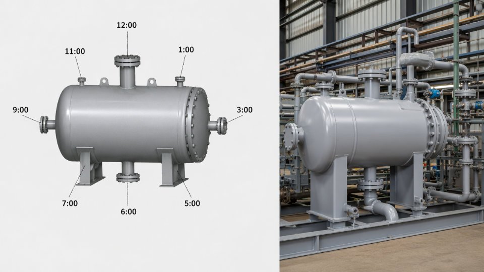
Orientation stated as clock position (for horizontal vessels) or azimuth in degrees from north or from a reference nozzle (for vertical vessels) eliminates ambiguous verbal descriptions that generate field rework. Facing — raised face, flat face, ring-type joint — must match your piping specification exactly; a wrong facing discovered at hydro-test is a costly remedy.
Site and Transport Dimensional Limits
Maximum diameter for highway transport without a special permit runs roughly 3.6–4.3 m in most jurisdictions, though this varies by route, country, and whether night travel or escort vehicles are permitted. Length limits commonly fall in the 30–40 m range for road, again route-dependent. If your site is off a mountain road or inland waterway, those limits may be tighter still.
Crane lift weight — including rigging, lifting lugs, internals if installed — needs a confirmed limit from your site lift study, not a guess. A vessel designed and fabricated to 85 tonnes that arrives at a site with an 80-tonne crane available is not a minor scheduling problem.
State your structural clearance: bay width, overhead obstruction height, and any underground utilities that restrict where a heavy-lift crane can be positioned. These constraints shape not just shipping but the fabricator’s lifting lug placement and the weight distribution report they’ll provide to your rigging contractor.
Material of Construction: Matching Metallurgy to Service Environment
Getting the metallurgy wrong on a custom pressure vessel is one of the most expensive mistakes in the procurement chain. It can surface during fabrication as a rejected weld procedure qualification, during inspection as a failed hardness test, or — worst case — years into operation as accelerating internal corrosion that forces an unplanned shutdown. Vendors need your material specification stated explicitly, not inferred from a service description.
Carbon Steel, Low-Alloy, and Stainless: Choosing the Right Baseline
SA-516-70 carbon steel is the workhorse for the majority of hydrocarbon and utility vessels operating below roughly 400°F (204°C) without aggressive corrosive species. It machines cleanly, welds predictably, and carries the lowest base material cost. If your service pushes past that temperature threshold — fired heaters, steam drums, hot separator service — the conversation shifts to low-alloy chromium-molybdenum grades such as SA-387 Gr. 11 or Gr. 22. These grades retain strength and resist hydrogen attack at elevated temperatures, but they demand preheat, controlled interpass temperature, and mandatory post-weld heat treatment (PWHT). That adds 3–7 days to fabrication time depending on vessel wall thickness and shop furnace capacity, which must be reflected in your delivery schedule.
Stainless steel, typically SA-240 316L for moderate chloride environments or where product purity is critical, is not a default upgrade — it is a specific engineering decision. The material cost premium over carbon steel runs 4x to 7x depending on market conditions and plate thickness. Fabrication labor also increases because fit-up tolerances tighten and sensitization risk during welding requires controlled heat input. If your reason for specifying 316L is simply “we always use stainless,” revisit that before the RFQ goes out. A clad or overlay option may serve the same corrosion requirement at significantly lower cost.
Wet H2S, Amine, and HF Service: NACE Requirements Are Not Optional
Any vessel handling wet sour gas, amine treating solutions, or hydrofluoric acid requires explicit reference to NACE MR0175/ISO 15156 (for sour service) or NACE SP0472 (for wet H2S in carbon steel equipment). These standards impose hardness limits — carbon steel and low-alloy base metal, weld metal, and heat-affected zone must all stay at or below 22 HRC. That single requirement cascades into your WPS/PQR documentation, filler metal selection, PWHT scope, and the hardness survey pattern required on production welds.
Wet H2S cracking failures almost always initiate in the HAZ of welds that met chemistry requirements but exceeded hardness limits due to inadequate PWHT or improper filler selection.True
Sulfide stress cracking (SSC) and hydrogen-induced cracking (HIC) are highly sensitive to hardness gradients in the HAZ. NACE MR0175/ISO 15156 Part 2 specifically addresses this mechanism and sets the 22 HRC threshold based on documented field failures and laboratory testing.
State the specific sour service standard in your RFQ. Vendors who have not qualified procedures to NACE requirements cannot simply bolt them on mid-fabrication.
Clad and Weld Overlay: When Solid Alloy Is Overkill
For vessels where the corrosive medium contacts only the internal surface — chloride-bearing process streams, dilute acid environments, some amine services — a carbon steel shell with an internal corrosion-resistant alloy (CRA) cladding or weld overlay often delivers the right metallurgy at a fraction of solid-alloy cost. Explosion-bonded clad plate per ASTM A264 requires bond strength testing (shear strength minimum typically 140 MPa) and a specified clad ratio, usually expressed as a minimum CRA thickness after forming — commonly 3 mm to 5 mm for 316L or 825 alloy. Weld overlay (strip or wire process) adds more fabrication time but allows localized application on nozzles and high-wear zones without specifying full clad plate.
If you are considering clad construction, your RFQ must specify: the CRA alloy and grade, minimum finished clad thickness, bond testing acceptance criteria, and whether overlay is acceptable as an alternative to roll-bonded plate. Leaving that open invites vendors to bid inconsistently.
Corrosion Allowance and Project Material Specifications
Corrosion allowance for carbon steel in typical hydrocarbon service runs 1.5 mm to 3 mm — the actual value depends on your predicted corrosion rate from process modeling, the design life of the asset, and any owner engineering standard that governs it. State the number explicitly in your datasheet. Vendors cannot guess at your corrosion rate, and two bids calculated on 1.5 mm versus 3 mm corrosion allowance are not comparable on a cost or weight basis.
If your project operates under an approved material list (AML) or a company-specific material specification — common in refinery expansions and long-term EPC frameworks — attach it to the RFQ package. Fabricators regularly carry plate inventory in standard mill grades. A last-minute restriction to a specific heat number origin or a proprietary specification they have never welded can add 4–10 weeks to procurement lead time alone.
Design Code, Stamp, and Certification Requirements for Your Jurisdiction
The single most common reason a fabricator has to stop work mid-project — not restart, stop — is discovering that the wrong code edition was assumed at the quoting stage. A vessel designed to ASME Section VIII Div.1 with a U-stamp cannot simply be relabeled for a European installation requiring PED 2014/68/EU CE marking. The engineering calculations, material certifications, weld procedure qualifications, and documentation package are fundamentally different. Lock this down before the RFQ goes out, not after the purchase order lands.
How End-Use Country Determines Which Code Governs
The vessel’s permanent installation location — not the buyer’s headquarters, not the EPC contractor’s country of origin — dictates the governing code. A US-based engineering firm procuring a vessel for a facility in Germany must specify PED CE marking regardless of where it prefers to source. Conversely, a Chinese state-owned refinery importing equipment for domestic use typically requires GB 150 compliance and a TS-stamp issued under CSEI (China Special Equipment Institute) oversight, even if the fabricator is located outside China.
The practical overlap matters: some fabricators hold both ASME U-stamp authorization and PED Module H or H1 approval, which compresses schedule. But assuming that capability without confirming it in the RFQ costs you 3–6 weeks of re-engineering minimum. State the installation country explicitly in your inquiry. If the project spans multiple countries under one EPC contract, list each jurisdiction and its required certification separately.
An ASME U-stamped vessel automatically satisfies PED CE marking requirements for European installations.False
ASME and PED are independent regulatory frameworks. ASME governs design calculation methodology and material traceability within its own code; PED requires conformity assessment under EU Directive 2014/68/EU, which includes its own essential safety requirements, notified body involvement, and Declaration of Conformity. A vessel can hold both, but only if specifically designed and documented to satisfy each independently.
National Board Registration and Data Report Documentation
For vessels installed in the United States and most Canadian provinces, National Board (NB) registration is not optional — it is a legal requirement in the majority of jurisdictions and mandatory for insurance coverage under most industrial property policies. The fabricator must hold an ASME Certificate of Authorization and submit a completed Form U-1 or U-1A data report to the National Board. The NB stamp is then stamped onto the nameplate alongside the ASME U-stamp.
Specify in your RFQ whether NB registration is required. If it is, the fabricator must have an authorized inspection agency (AI) involved from the start — typically an ASME-accredited AI from a major insurer or an independent inspection organization. This affects inspection hold points, documentation sequencing, and the final MDR (Manufacturer’s Data Report) structure. Leaving this out of the initial inquiry is a schedule risk, not a paperwork formality.
Third-Party Inspection: Customer-Nominated TPI vs. Manufacturer’s In-House AI
Many EPC contracts and owner specifications require a customer-nominated third-party inspection body — Bureau Veritas, TÜV Rheinland, SGS, Intertek, and similar organizations are common choices. The distinction matters operationally. A manufacturer’s in-house authorized inspector works within the shop’s quality system and follows the ASME-defined hold and witness point schedule. A customer-nominated TPI may impose additional witness points, require advance notification windows of 5–10 business days per inspection event, and conduct independent document reviews that add cycle time.
Name the TPI in your RFQ and attach or reference their applicable inspection and test plan (ITP) format if one exists. Fabricators need to price TPI coordination into their schedule and overhead. Leaving TPI requirements unspecified until after award routinely adds 2–4 weeks to project completion, particularly when the TPI’s regional office availability is constrained.
Special Process Certifications: PWHT, Impact Testing, and NDE Qualification
Three process certification requirements generate the most last-minute surprises in pressure vessel fabrication.
Post-weld heat treatment (PWHT) must follow a qualified procedure — not just a generic furnace log. If your service conditions or material thickness mandate PWHT per UG-56 or your applicable code, the fabricator must have a documented heat treatment procedure with calibrated thermocouple records and hold a procedure qualification record (PQR) that covers your base metal group and filler metal classification. Ask for this specifically in the RFQ technical requirements.
Impact testing per UG-84 applies when the minimum design metal temperature (MDMT) falls below the exemption curves for a given material and thickness. For low-temperature service — cryogenic applications, cold-climate outdoor installations — Charpy V-notch impact test results must be included in the material certification package. The test temperature and absorbed energy requirements vary by material specification and code edition. Specify your MDMT in the RFQ; without it, a fabricator cannot determine whether impact testing is required and may quote without it, creating a gap that surfaces during final documentation review.
NDE method qualification records — including UT operator certifications, RT procedure qualifications, and PT/MT method statements — should be called out if your owner specification or code interpretation requires them beyond the minimum. ASME Section VIII Div.1 sets baseline NDE requirements, but many owner specs reference SNT-TC-1A or ISO 9712 for personnel qualification, adding a documentation layer the shop must confirm it can satisfy.
Export Documentation Package: What MDR Structure You Should Specify
If the vessel crosses an international border, the documentation package requirement deserves the same attention as the mechanical design. A complete Manufacturer’s Data Report (MDR) for export typically includes: material mill certificates with full chemical and mechanical properties traceable to each heat number; weld procedure specifications (WPS) and PQRs; welder qualification records; dimensional inspection reports; hydrostatic or pneumatic pressure test certificates with chart records; PWHT records if applicable; NDE reports; nameplate rubbing or photograph; and the applicable code data report form (U-1, U-1A, or equivalent).
Some jurisdictions — and many owner companies — also require a material traceability matrix linking each major component back to its mill certificate, heat number, and applicable code compliance statement. This is not excessive paperwork. On a sour service vessel with NACE MR0175 hardness requirements, traceability to the hardness test results for each weld and HAZ is a code obligation, not a preference.
State your MDR format requirements in the RFQ. If your company has a standard MDR checklist, attach it. Fabricators who receive a clear documentation scope can price it accurately and avoid the end-of-project invoice dispute over “additional documentation preparation” that is otherwise nearly universal on complex custom vessels.
Inspection, Testing, and NDE Scope: Defining Quality Hold Points Before Quoting
Most cost disputes between buyers and fabricators don’t originate in material pricing — they originate in NDE scope. When a buyer submits an RFQ without a defined Inspection and Test Plan, the vendor fills that gap with assumptions. Those assumptions may be conservative enough to inflate the quote, or optimistic enough to generate a change order after the purchase order is signed. Neither outcome serves the project.
Lock in the ITP scope before you request pricing. Here is what that means in practice.
Radiographic vs. Ultrasonic Weld Examination
For vessels designed to ASME Section VIII Div.1, the examination category directly determines joint efficiency — and therefore wall thickness. Full RT (100% radiography) allows a joint efficiency of 1.0, meaning thinner shell plate. Spot RT (10%) drops that to 0.85, requiring a heavier shell to compensate. On a large vessel, the additional material cost from spot RT can partially or fully offset the apparent savings in NDE labor, particularly when shell diameters exceed 48 inches or design pressures push above 300 psi.
RT is the default where geometry permits — straight seams, accessible welds, film or digital detector placement clearance. UT (ultrasonic testing), specifically TOFD or phased-array UT, is preferred on thick-wall vessels above roughly 2 inches nominal, nozzle-to-shell welds with complex geometry, and austenitic stainless or clad materials where RT sensitivity is reduced. State in your RFQ which method you require and at what coverage percentage. Leaving this open invites the vendor to quote whichever is cheapest to perform, not whichever is most appropriate for the service.
Hydrostatic vs. Pneumatic Pressure Test
ASME UG-99 governs hydrostatic testing; UG-100 permits pneumatic testing only when the vessel design or support structure cannot accommodate the weight of water, or when traces of liquid are harmful to the intended service (certain catalyst systems or cryogenic vessels where moisture contamination is a real concern). Pneumatic testing is not a shortcut — it requires the test pressure to be built up in stages, typically 10% increments with a hold, and mandates a preliminary leak test at no more than 25 psi using a gas that can be safely detected.
Pneumatic pressure testing carries significantly higher stored energy risk than hydrostatic testing at the same test pressure, because gases are compressible.True
A vessel filled with pressurized gas stores orders of magnitude more energy than one filled with liquid at the same pressure. ASME and most jurisdictions require additional safety precautions — personnel exclusion zones, staged pressurization, acoustic emission monitoring in some cases — precisely because a pneumatic test failure releases that energy instantaneously.
Specify which test method applies to your service. If you require pneumatic, your RFQ must acknowledge the additional safety protocol cost, which can range from modest to significant depending on vessel volume and site requirements.
PMI Scope: How Broad Is Your Net?
Positive material identification is not automatically comprehensive. You must define whether PMI applies to weld metal only, to all pressure-retaining base materials, or to every component including flanges, fittings, and fasteners. XRF (X-ray fluorescence) is fast and portable, adequate for verifying alloy grade on base metal. It cannot reliably quantify carbon content, which matters on low-alloy steels. OES (optical emission spectrometry) is slower and more expensive but gives a full elemental breakdown including carbon — necessary when verifying P-number classifications or confirming compliance with NACE MR0175/ISO 15156 hardness and chemistry limits for sour service.
Hardness Testing for PWHT and Sour Service
Post-weld heat treatment verification requires hardness testing on the weld, HAZ, and base metal — not just the weld bead. For vessels in H2S service, NACE MR0175/ISO 15156 sets a hardness ceiling of 22 HRC for carbon and low-alloy steels across all three zones. Specify the sampling frequency (every weld joint, random 10%, or per heat of material) and the acceptance criteria explicitly. A fabricator who doesn’t see this in the RFQ will quote minimum effort.
Witness Points, Hold Points, and Review Points
These three terms are not interchangeable, and conflating them is a routine source of schedule disruption.
| Point Type | Definition | Consequence if Missed |
|---|---|---|
| Hold Point | Work cannot proceed without authorized witness present | Fabrication stops; vendor notifies buyer/TPI in advance |
| Witness Point | Buyer or TPI intends to attend; work may proceed if no-show after notice period | Vendor documents, proceeds after defined waiting window |
| Review Point | Buyer reviews documentation only; no physical attendance required | Records submitted; work continues without interruption |
Define in your ITP which activities fall into each category — fit-up inspection, final RT review, hydro test, PMI records audit — and who has authority to witness: your internal inspector, a third-party inspection agency, or the Authorized Inspector under the ASME stamp program. Vendors price mobilization, scheduling holds, and documentation packages differently depending on witness density. A vessel with four hold points costs more to execute than one with four review points, and that difference belongs in the quote, not in a change order.
Drawings, Datasheets, and Reference Documents to Attach to Your RFQ Package
A well-written process description alone is rarely enough. Vendors building a quote need a consistent technical picture across every discipline — mechanical, piping, instrumentation, civil — and the only reliable way to deliver that is a structured document package. When that package is thin or inconsistent, estimators fill gaps with assumptions, and those assumptions tend to be conservative. You pay for the uncertainty.
Vessel Datasheet: The Single-Document Technical Anchor
For unfired pressure vessels, use an API 660-style datasheet (or TEMA sheet for shell-and-tube heat exchangers). The mandatory fields are not negotiable: design pressure and MAWP, minimum design metal temperature (MDMT), test pressure, corrosion allowance, shell and head geometry, nozzle schedule with ratings, and design code edition. Leave any of these blank and a competent vendor will either call you for clarification — adding 3–7 days to the cycle — or quote a conservative interpretation that inflates price.
MDMT deserves particular attention. A vessel destined for outdoor installation in northern climates or LNG-adjacent service may need impact testing per UCS-66 curves, which adds cost and lead time. If you know the site ambient minimum, state it. Don’t let the vendor guess.

P&ID Excerpt: Context the Datasheet Cannot Provide
Attach the relevant P&ID sheet — or at minimum a marked extract showing the vessel, its connected line classes, and the relief valve set pressure. This single document tells the vendor the upstream and downstream piping pressure class, which directly influences nozzle flange ratings. It also confirms whether the relief device discharges to atmosphere or a closed header, which affects outlet nozzle sizing.
A pressure vessel nozzle flange rating can be one or two classes higher than the vessel's own design pressure when the connected line class requires it.True
Piping class dictates flange rating per ASME B16.5 or B16.47; if the connected line is Class 600 but the vessel design pressure would only require Class 300, the vendor must match the piping class or document an engineering deviation. Omitting the P&ID excerpt hides this requirement entirely.
Without the P&ID, nozzle ratings are often under-specified at inquiry stage and corrected at approval drawing — after the purchase order is placed, when change orders are expensive.
Plot Plan and Equipment Layout Sketch
Even a rough dimensioned sketch showing where the vessel sits in the plot, which direction nozzles face, and what maintenance clearance is required prevents a class of late-stage problems that nobody budgets for. Vendors need to know whether top-entry nozzles must clear a pipe rack, whether the skirt has a maintenance manway, and whether bundle pull space must be reserved for a horizontal heat exchanger. These details drive structural design, lifting lug placement, and sometimes vessel orientation. A sketch that takes your piping lead two hours to mark up can eliminate one to three weeks of back-and-forth during detailed engineering.
Project Specifications: Painting, Insulation Supports, and Nameplate
Most EPC projects carry project-specific coating specifications — surface prep grade, paint system, DFT requirements, holiday testing. Attach the relevant spec number and revision. The same applies to insulation support rings if the vessel will be insulated, and to nameplate content requirements (CE marking data, NB number format, language requirements for the destination country). These items are low-cost to specify upfront and expensive to retrofit after blast and paint.
Previous Similar Vessel Drawings as Reference
If your project is a repeat unit or a capacity expansion, attach drawings from the previous similar vessel — even if they are “for reference only.” Vendors use these to calibrate complexity, identify non-standard features, and reduce clarification cycles by 30–60% in typical cases, depending on how closely the new unit matches the reference. Mark them clearly as reference documents to avoid confusion with the actual design basis.
Utility Summary for Heat Exchangers
For shell-and-tube and other heat transfer equipment, the utility summary is as important as the datasheet. Specify shell-side and tube-side fluid identity, flow rates, inlet and outlet temperatures, fouling factors (typically expressed in m²·K/W or ft²·h·°F/BTU), and allowable pressure drop on each side. Allowable pressure drop is frequently omitted and frequently consequential — a tighter drop budget can force a larger shell diameter or a different tube layout, both of which affect cost. State whether the fouling factor is a client standard value or a measured service value, because vendors weight them differently when sizing heat transfer area margin.
Delivery, Packaging, and Site Logistics Data That Affects Lead Time and Cost
Logistics data is the section of an RFQ package that gets skipped most often, and it is frequently the reason a quoted price bears no resemblance to the actual landed cost. A vessel fabricator pricing an inquiry without a firm delivery date, an Incoterms designation, or a shipping mode constraint is essentially guessing at a significant portion of their cost exposure. You end up with quotes you cannot compare and change orders you did not budget for.
Required Delivery Date and Its Contractual Weight
State clearly whether your required delivery date is a hard contractual milestone tied to a construction schedule or a planning target. These two carry very different implications for a fabricator. A firm milestone tied to liquidated damages clauses will require the vendor to carry schedule risk, which gets priced in — expect a 5–15% premium on fabrication cost depending on current shop loading and lead times for raw materials like pressure vessel plate or forgings. A target date allows a vendor to optimize sequencing across their shop floor and usually yields a better price.
If the vessel is on the critical path — a column that must be set before structural steel erection closes in around it, for example — say so explicitly. That context determines whether a vendor will quote overtime fabrication, expedited NDE services, or priority raw material sourcing, all of which carry real cost consequences.
Incoterms and What Gets Buried in the Quote
Specify the Incoterms revision year and term: EXW, FOB, CIF, or DAP are the most common for international pressure vessel procurement. Under EXW, the vendor’s scope ends at the factory gate and your team or freight forwarder carries full transport risk. Under DAP, the vendor includes freight, export clearance, and delivery to your named site — a scope that can add 8–20% to the base fabrication price depending on vessel weight, destination country, and current ocean freight rates. Leaving Incoterms unspecified forces vendors to make different assumptions, and your bid comparison becomes meaningless.
Leaving Incoterms unspecified on a pressure vessel RFQ is a common source of apples-to-oranges quote comparisons among EPC procurement teams.True
Different vendors will assume different freight inclusion, insurance, and export documentation scopes, making direct price comparison unreliable without a stated Incoterms term.
Shipping Mode Constraints for Large Equipment
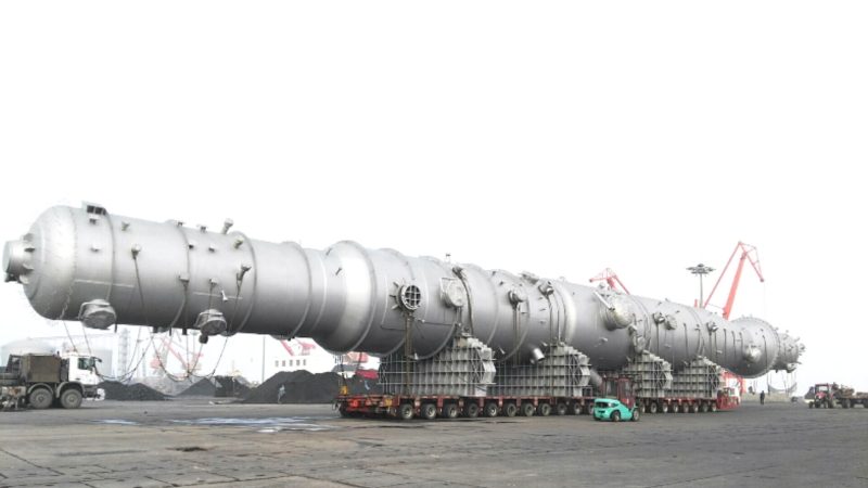
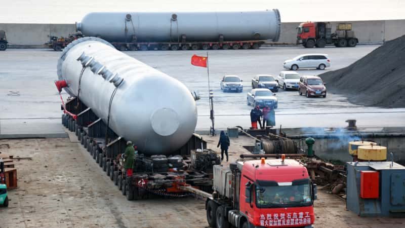
For vessels above roughly 3.5 m outside diameter or columns exceeding 18–20 m in length, a standard 40-foot container is no longer an option. Specify whether your project requires flat-rack container, open-top, break-bulk, or heavy-lift vessel charter. This affects not just freight cost but fabrication scope: nozzle orientation, removable internals, temporary shipping saddle design, and the need for over-dimensional permits on inland road routes. Provide any known route restrictions — bridge height clearances, road weight limits between port and site — so the vendor can design lifting lugs and shipping saddles accordingly from the start rather than retrofitting them.
Surface Preparation and Coating Specification
Define whether you require shop primer only, an intermediate coat, or a full finish topcoat system with color. Specify the surface preparation standard — Sa 2.5 per ISO 8501-1 is common for carbon steel in corrosive service — and state whether holiday testing to NACE SP0188 or equivalent is a hold point. A full three-coat system with holiday test and witness adds measurable cost and shop time relative to a simple primer; the delta varies with vessel surface area but is not trivial on large-diameter equipment.
Preservation and Packing for Long Transit or Site Storage
If the vessel will spend more than four to six weeks in transit or sit in laydown storage before installation, define your preservation requirements explicitly. Nitrogen blanketing of internals, desiccant packs inside nozzle openings, and VCI film wrapping of machined flanges and flange faces are standard for overseas shipments to humid climates or extended storage scenarios. These are not automatic inclusions — vendors price them only when specified. Skipping them on equipment bound for a coastal or tropical site and then finding flash rust on gasket seating faces during pre-commissioning inspection is an avoidable and expensive problem.
Frequently Asked Questions About Custom Pressure Vessel RFQ Data

What is the minimum information needed to get a ballpark budget estimate?
Five data points define a rough-order-of-magnitude figure: operating pressure, design temperature, vessel volume or shell diameter and tangent-to-tangent length, fluid service (including phase and hazard classification), and the governing design code. Without all five, any number a vendor gives you is a guess dressed up as a quote. Operating pressure alone spans a wide range — ASME Section VIII Div.1 vessels are routinely designed anywhere from 15 psi to 3,000 psi, and the cost curve is not linear. A 150 psi carbon steel vessel and a 1,500 psi alloy vessel in the same nominal volume can differ by a factor of four or more in fabricated cost. Even at the ROM stage, fluid service matters because H2S or HF service immediately pulls in NACE MR0175/ISO 15156 compliance, which changes material sourcing and post-weld heat treatment scope before a single plate is rolled.
How do I specify MDMT if I do not have a process simulation yet?
Use the lowest expected ambient temperature at the installation site as a conservative starting point and label it explicitly as preliminary in your RFQ. If the plant is in a northern continental climate, that could be -40 °F / -40 °C; a coastal tropical site might only need 14 °F / -10 °C. The practical consequence is significant: a vessel designed for -20 °F versus -50 °F may require impact testing per UCS-66 or a shift to a tougher plate grade such as SA-516-70N or SA-537 Cl.1, both of which affect material lead time and cost. Flag the value clearly so the vendor quotes with the correct Charpy impact test requirements rather than baking in assumptions that trigger a change order later.
Using site ambient temperature as a preliminary MDMT is a recognized conservative engineering practice when process simulation data is unavailable at the RFQ stage.True
ASME Section VIII Div.1 and its supporting engineering practice allow minimum design metal temperature to be set by the lowest anticipated metal temperature in service, which conservatively includes ambient exposure during startup, shutdown, or depressurization. Flagging it as preliminary for vendor confirmation is standard EPC practice.
Should I specify corrosion allowance, or let the vendor decide?
Always state your required corrosion allowance. Vendors will sometimes offer an alternative if your value seems conservative for the service, but the owner’s process engineer must own this number. A vendor-recommended corrosion allowance that later proves insufficient creates a liability dispute, not a warranty claim. Corrosion allowance depends on fluid composition, velocity, inhibitor program, and inspection interval — information the fabricator rarely has in full at the quoting stage. Common ranges are 1.5 mm to 6 mm for aqueous hydrocarbon service, but the right value depends entirely on corrosion rate data from your process team or a corrosion engineer.
What documents are required for an ASME U-stamp vessel exported to the United States?
You need to supply or agree on the vessel datasheet referencing ASME Section VIII Div.1, confirm National Board registration intent (which requires a completed U-1 Data Report at completion), and provide the name and contact of your customer-nominated Authorized Inspector from an ASME-accredited inspection agency. Without an AI assigned early, the fabricator cannot schedule the mandatory code inspections, and the vessel cannot be legally stamped. Delay in AI assignment is one of the most common causes of shipping postponement on U-stamp export projects.
How does adding a third-party inspection body affect price and schedule?
TPI witness and hold points typically add 5–15% to the total inspection line item cost, and 1–2 weeks to the overall fabrication schedule, depending on the inspector’s availability and travel logistics. The spread is wide because it depends entirely on how many hold points are defined versus witness or review points. A hold point stops production until the inspector physically signs off. A witness point requires notification but allows work to continue if the inspector cannot attend within a defined window. A review point is documentation only. Define these categories explicitly in your ITP before quoting — giving vendors a marked-up inspection matrix rather than a generic “TPI required” note lets them schedule and price accurately instead of padding for worst-case assumptions.
Can I request a quote without a P&ID?
You can, but scope exclusions will be significant. At minimum, provide a written process flow description covering fluid source, destination, and operating sequence, plus a preliminary nozzle list showing size, rating, and service for each connection. Without a P&ID, vendors cannot confirm battery limits, instrument tap locations, safety valve sizing basis, or proper nozzle reinforcement loads. Expect the quotation to carry explicit assumptions on all of those points, and expect a scope alignment meeting before a purchase order is placed. If you are still in early FEED, that is a reasonable position — just don’t treat the resulting price as firm.