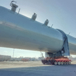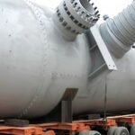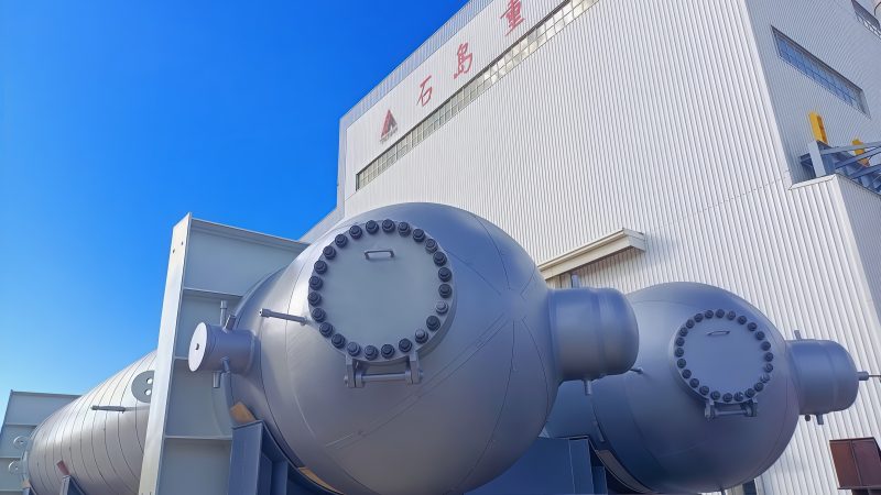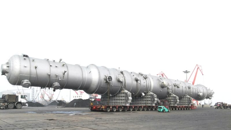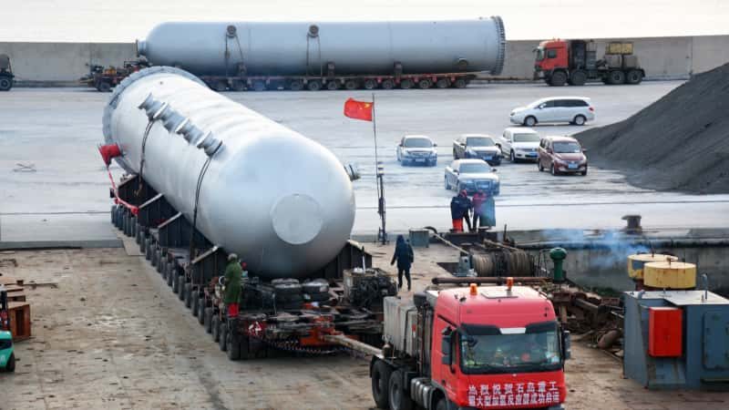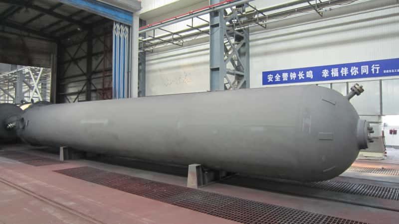

Liquid carryover from an undersized or poorly specified acid gas knock-out drum doesn’t announce itself politely. It shows up as a flare tip failure, a compressor seal wash-out, or — worst case — an uncontrolled liquid slug igniting at grade level during an emergency depressurization event. The maintenance cost of one damaged wet-gas compressor stage typically runs well into six figures, and that’s before accounting for lost production, unit shutdown, and the regulatory review that follows any flare system incident. The vessel sitting quietly upstream of your flare header is the last line of defense, and it is routinely under-engineered.
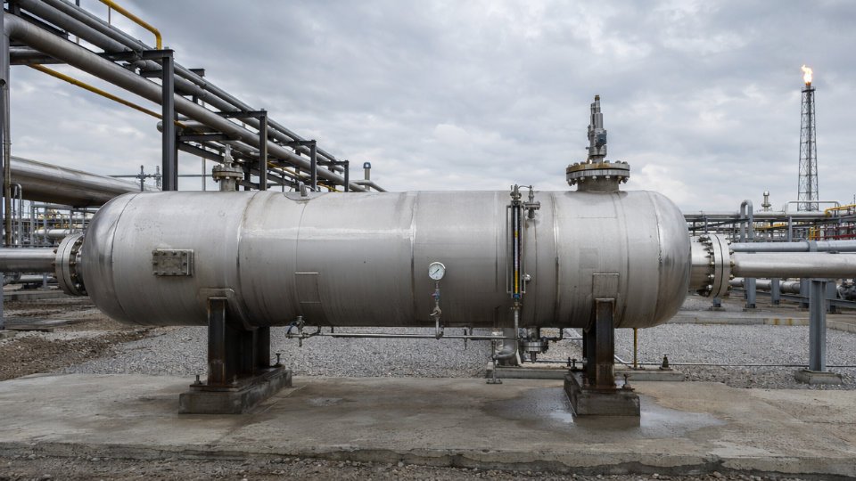
An acid gas knock-out drum is a pressure vessel installed in refinery and chemical plant flare or acid gas systems to separate entrained liquids — including hydrocarbon condensate, amine solution, and water — from the vapor stream before it reaches downstream equipment or the flare tip. Properly sized units use horizontal configurations with L/D ratios between 3:1 and 5:1, design pressures typically in the 50–150 psig range for flare header service, and liquid holdup capacity sufficient for 10–20 minutes at maximum credible release flow. Any H2S partial pressure exceeding 0.05 psia in the gas phase triggers full sour-service material requirements under NACE MR0175/ISO 15156.
What makes these vessels genuinely tricky isn’t the thermodynamics — it’s the gap between normal operating conditions and the brief, violent surge scenarios the drum actually has to survive. Most of the design decisions that matter happen at the edges: the credible-worst-case liquid release rate, the material spec when H2S concentration climbs during an upset, the nozzle orientation that determines whether your inlet device works or just adds pressure drop. The sections that follow work through each of those decisions in the order an engineer or procurement manager actually needs them.
Process Conditions That Define Acid Gas KO Drum Service: H2S, CO2, Amine Carry-Over, and Multiphase Slugs
The fluid environment inside an acid gas KO drum is rarely a single clean stream. What actually arrives at the drum inlet is a mixture shaped by dozens of upstream events happening simultaneously — routine relief valve weeping, compressor seal purges, amine contactor upsets, and occasionally a full emergency blowdown. Getting the design right starts with mapping that mixture honestly.
Acid Gas Stream Composition in Refinery Flare Headers
H2S concentrations in refinery flare header gas vary widely depending on crude slate and upstream unit configuration. Hydrotreater and hydrocracker relief streams routinely carry H2S mole fractions in the range of 5–30%, while sour water stripper overhead streams can push higher during upsets. CO2 is almost always present alongside H2S — typically 2–15 mol% in refinery service, higher in natural gas processing and amine regeneration overhead service — and its presence directly affects the dew point behavior of the gas phase and accelerates corrosion in condensed water films.
Amine carry-over from upstream absorbers deserves its own attention because it is frequently underestimated during the design phase. When a contactor trips or experiences foaming, entrained amine solution — typically methyldiethanolamine (MDEA) or diethanolamine (DEA) at 30–50 wt% concentration — travels downstream and collects in the KO drum sump. That liquid is not neutral. It is reactive, it degrades under heat and oxygen ingress, and its degradation products are corrosive to carbon steel in ways that do not show up in a clean amine analysis. Designing the drum’s liquid outlet and level control as if this liquid is simply water is a common and costly mistake.
Hydrocarbon condensates complicate the picture further. Light ends that condense in the flare header — C3 through C6 fractions, primarily — form a separate hydrocarbon liquid phase that floats above the aqueous amine layer. This two-liquid-phase system requires the drum internals and outlet nozzle placement to account for both layers, not just total liquid volume.
Slug Flow and Liquid Surge: The Transient Conditions That Govern Drum Volume
The worst-case scenario for a KO drum is not steady-state operation. It is the liquid slug that arrives in the first 30–90 seconds after a major relief valve opens or a compressor trips. These slugs form because liquid accumulates in low points of the flare header piping during normal operation and then mobilizes suddenly when gas velocity spikes.
The surge volume that arrives can be substantial. Flare system KO drums are typically sized to provide 10–20 minutes of liquid holdup at the maximum credible release flow rate, but the real design driver is often the initial slug volume — a quantity that depends on header pipe diameter, total header length, and the number of low-point accumulation areas in the network. Undersizing the drum volume by even 15–20% can result in liquid carryover into the flare stack, which creates a flare rain-out event: burning liquid falling back to grade. That is a safety incident, not just an operational nuisance.
Nozzle sizing follows the same logic. The inlet nozzle must handle the slug momentum without creating a pressure pulse that stalls relief valve discharge or causes liquid re-entrainment into the gas outlet.
Sour Service Thresholds and What They Mean at the Design Stage
The metallurgy question is settled by a single calculation: H2S partial pressure in the gas phase. When that value exceeds 0.05 psia — the threshold defined in NACE MR0175/ISO 15156 — the vessel is formally in sour service, and carbon steel without hardness control is no longer acceptable.
A KO drum handling flare gas from hydrotreater relief streams will almost always exceed the 0.05 psia H2S partial pressure threshold for sour service classification under NACE MR0175/ISO 15156.True
Hydrotreater relief streams routinely carry H2S mole fractions of 5–30%. Even at the lower end, at typical flare header pressures of 50–150 psig, the resulting H2S partial pressure comfortably exceeds the 0.05 psia sour service trigger.
What sour service classification means practically: weld hardness must be controlled to HRC 22 maximum, heat-affected zones require post-weld heat treatment (PWHT), and bolt and fastener materials must meet the standard’s hardness limits — details that affect procurement lead times and fabrication cost. The aqueous phase pH compounds this. If the condensed water phase drops below pH 4, which happens when CO2 partial pressure is high and amine carry-over is insufficient to buffer it, sulfide stress cracking (SSC) risk increases sharply even at H2S concentrations below what would otherwise concern an engineer. Both variables need to be evaluated together at the process design stage, not resolved as a shop floor afterthought.
Mechanical Design Parameters: Vessel Geometry, Internals Selection, and Sizing Methodology
Sizing an acid gas KO drum is not a template exercise. The vessel geometry, internal devices, and liquid holdup volumes must be derived from actual process conditions — inlet flow regime, liquid loading, slugging frequency, and the specific gravity differential between phases. Getting any of these wrong produces a drum that either floods during an upset or passes liquid carryover into the flare header, with consequences ranging from flare tip damage to an uncontrolled liquid seal event.
Souders-Brown Application and Orientation Selection
The Souders-Brown equation establishes the maximum allowable vapor velocity by balancing drag against the settling velocity of the design droplet size. For acid gas KO drum service, the design K-factor typically falls between 0.05 and 0.15 ft/s (referenced to the vessel cross-section) — where the actual value depends on operating pressure, the presence of mesh pads or vane demisters, and acceptable carryover rate for the specific flare system.
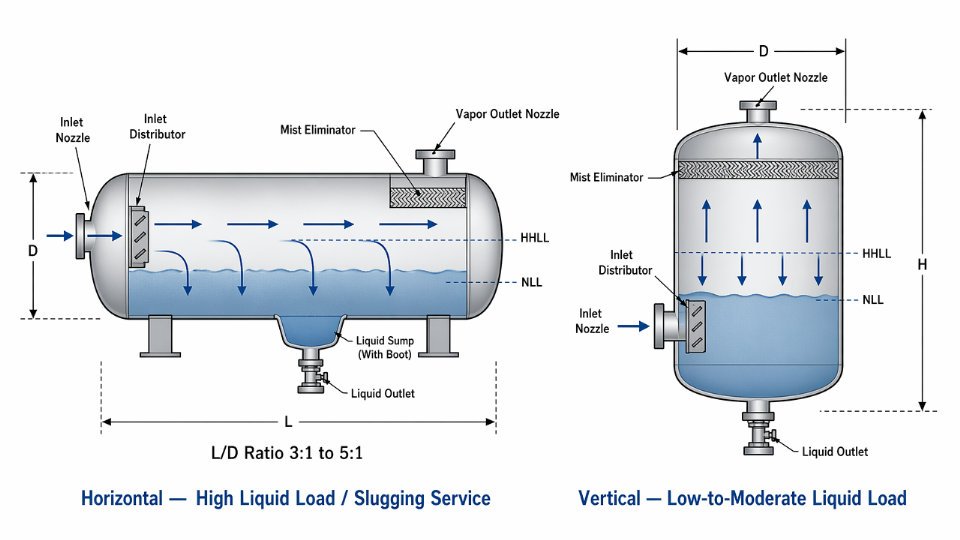
Vertical orientation suits low-to-moderate liquid loading where gravity separation is the primary mechanism and plot space is limited in one horizontal dimension. Horizontal orientation becomes preferable — often necessary — when inlet flow arrives with significant liquid slugging, because the longer vapor travel path and larger liquid surface area provide meaningful slug dampening that a vertical drum simply cannot match at the same vessel weight. L/D ratios for horizontal acid gas KO drums in flare header service commonly range from 3:1 to 5:1; the tighter end of that range applies to space-constrained installations, while the wider end is driven by liquid holdup requirements rather than vapor separation.
Internal Device Selection for Acid Gas Service
A bare vessel shell relies entirely on gravity. For most acid gas and sour flare service, that is not sufficient. The choice of internals depends on the combination of liquid loading and gas velocity you are designing for.
Inlet vane distributors should be treated as a baseline requirement, not an optional upgrade. They break up the inlet jet, distribute flow evenly across the vessel cross-section, and strip the coarsest liquid fraction at the entry point before vapor reaches any downstream mist elimination stage. Skipping them on a high-velocity inlet produces a channeling effect that overwhelms even a well-specified mesh pad.
For the mist elimination stage: mesh pads work well at steady, moderate gas velocities and light liquid loading but are prone to liquid re-entrainment and fouling in amine carryover service. Vane-pack demisters tolerate higher liquid loads and are easier to drain in sour service — an important practical consideration. Cyclonic inlets or inline cyclone bundles handle high liquid fractions and slugging better than either, but they carry a higher pressure drop and require more careful sizing at low-flow turndown conditions. In high-liquid-loading acid gas service, a common effective combination is a cyclonic inlet distributor paired with a downstream vane-pack; for dilute sour gas streams with minimal liquid, a simple inlet vane followed by a mesh pad is often adequate and reduces cost.
Vane-pack demisters outperform wire mesh pads in acid gas service with amine carryoverTrue
Amine solutions foul wire mesh rapidly, increasing differential pressure and causing liquid re-entrainment. Vane packs have open drainage channels that resist blinding and can be cleaned or replaced in sections without vessel entry.
Liquid Holdup Volume and Sump Sizing
KO drums in flare systems are typically sized for 10 to 20 minutes of liquid holdup at the maximum credible release flow rate — the actual target within that range depends on whether automatic level control and pump-out systems are available, or whether the drum must hold inventory until manual intervention. If the drain system is manual, design toward the upper end.
Setting the high-high liquid level (HHLL) trip point requires working backward from three constraints: the minimum vapor disengagement height above the liquid surface, the volume required between normal operating level and HHLL for the credible slug volume, and the instrument response time for the level trip to actuate the inlet isolation or pump-out system. Compressing any of these margins to save vessel height is a design error with direct safety consequences.
Where free water accumulates — common in any sour service handling wet acid gas — a dedicated boot or sump should be sized separately from the main liquid inventory. Boot diameter typically ranges from 12 to 24 inches depending on aqueous-phase flow rate; the critical dimension is that the boot must provide enough residence time for hydrocarbon-water separation before the aqueous phase reaches the drain valve. Undersizing the boot causes hydrocarbon to exit with the produced water, creating both a waste treatment problem and a level measurement error if the instrument is reading a mixed-phase interface.
Sour Service Metallurgy and Weld Procedure Requirements for H2S-Containing Streams
The threshold that changes everything in acid gas KO drum procurement is deceptively small: 0.05 psia H2S partial pressure in the gas phase. Above that value, NACE MR0175/ISO 15156 governs your material selection and weld procedure qualification — full stop. Many procurement packages for flare knockout vessels list “carbon steel per ASTM A516 Gr. 70” and stop there, as if plate specification alone satisfies sour service requirements. It does not. What follows describes the actual qualification pathway and where fabrication shops — even experienced ones — routinely leave gaps.
Carbon Steel Qualification Under NACE MR0175/ISO 15156
For carbon and low-alloy steel pressure vessels in H2S service, Part 2 of ISO 15156 sets hardness as the primary control parameter. Base metal and weld metal hardness must not exceed HRC 22 (equivalent to approximately 237 HBW or 248 HV10). This limit applies to the heat-affected zone as well — a point that gets underweighted during fabrication review. A weld that passes visual and radiographic examination can still fail sour service qualification if HAZ hardness testing reveals localized values above that ceiling.
Carbon equivalent (CE) directly controls HAZ hardness. Most fabricators target a CE below 0.43 using the IIW formula (CE = C + Mn/6 + (Cr+Mo+V)/5 + (Ni+Cu)/15) for plate thicknesses above 25 mm, though the acceptable range shifts depending on heat input and preheat practice. Procurement packages should specify maximum CE on the mill test report, not leave it to the plate mill’s standard production window.
Post-weld heat treatment is mandatory for most carbon steel sour service vessels above a threshold wall thickness — typically 19 mm (¾ inch) per ASME VIII Div. 1, though sour service frequently makes PWHT advisable even below that thickness to relieve residual stress that would otherwise accelerate sulfide stress cracking. PWHT parameters — hold temperature range (typically 595–650°C for carbon steel), ramp rates, and minimum hold time — must appear explicitly in the weld procedure specification, not simply reference the code minimum.
SSC and HIC: How Design Choices Either Load or Unload the Risk
Sulfide stress cracking is a brittle fracture mechanism driven by atomic hydrogen absorbed at crack tips under tensile stress in a wet H2S environment. HIC is a different mechanism — planar cracking driven by hydrogen accumulation at internal laminations or non-metallic inclusions in rolled plate, with no applied stress required. Both can destroy a vessel that meets standard pressure design requirements.
Specifying ASTM A516 Gr. 70 with supplemental HIC testing per NACE TM0284 addresses the plate lamination risk. Acceptable results depend on the crack length ratio (CLR ≤ 15%), crack thickness ratio (CTR ≤ 5%), and crack sensitivity ratio (CSR ≤ 2%) — values that should be written into the material requisition, not assumed. Sulfide stress corrosion resistance testing per NACE TM0177 Method A (tensile specimens in NACE solution at ≥72 hours) should be required for heavier forgings used at nozzle necks and flanges.
Nozzle geometry contributes more to SSC risk than many specification writers realize. Reinforcing pad welds on nozzles introduce residual stress concentrations at the pad-to-shell junction. Full-penetration set-in nozzles with contoured transitions, combined with complete PWHT of the assembled nozzle joint, carry meaningfully lower cracking risk than pad-reinforced configurations in aggressive sour service.
PWHT alone guarantees protection against sulfide stress cracking in sour service carbon steel vesselsFalse
PWHT reduces residual stress and softens the HAZ, which lowers SSC susceptibility, but it is not sufficient without hardness verification, controlled CE, and appropriate plate specification. Vessels that pass PWHT but retain HAZ hardness above HRC 22 due to high CE plate or excessive heat input remain at elevated SSC risk.
Weld Procedure Qualification and Third-Party Inspection Hold Points
WPS and PQR documentation under ASME Section IX is the baseline — but sour service adds supplemental requirements that the standard code does not mandate on its own. Impact testing (Charpy V-notch) at the qualification stage provides a check on HAZ toughness that complements hardness testing. Minimum absorbed energy requirements, typically 27 J at the design minimum temperature, should be specified in the project quality plan.
Third-party inspection hold points should be fixed — not witness points that can be waived — at weld fit-up verification (confirming joint geometry before welding begins), mid-weld hardness checks on multi-pass heavy-wall joints, PWHT temperature chart review, and post-PWHT hardness survey. A floating witness point schedule gives fabrication shops the opportunity to compress timelines in ways that compromise sour service compliance. The consequence of missing a hardness exceedance at weld completion, then hydrotest, then shipment, is a vessel that enters service with a latent failure mechanism that may not manifest for months — until an upset pushes liquid H2S against a susceptible weld zone at a stress concentration.
Flare System Integration: Pressure Drop Allocation, Drain Systems, and Isolation Philosophy
The KO drum does not exist in isolation. Its performance — and critically, its failure modes — are inseparable from the flare network it sits inside. Engineers who treat the drum as a standalone vessel specification and ignore the hydraulic and operational context around it will eventually face either a relief device that fails to lift or a drain system that becomes a confined-space fatality waiting to happen.
Pressure Drop Allocation and Back-Pressure Budgeting
Every flare relief system starts with an allowable back-pressure limit at each relief device’s outlet flange. For conventional spring-loaded PSVs, API 520 Part II limits the allowable built-up back-pressure to roughly 10% of set pressure — for balanced bellows valves, the limit is higher but still finite. That budget has to be shared across the entire flow path: flare header piping, the KO drum itself, the seal drum or water seal, and the stack.
The KO drum’s inlet nozzle is where pressure drop allocation goes wrong most often. An undersized inlet nozzle — or one with an abrupt geometry rather than a properly designed impingement baffle or tangential entry — can consume 2–5 psi of the back-pressure budget by itself during a major relief event. At low set pressures (say, a 15 psig PSV on a low-pressure amine flash drum), that magnitude of inlet loss is enough to prevent the valve from fully opening. The result is not a safe partial release; it is an overpressure scenario disguised as a functioning relief system.
The practical rule: size the KO drum inlet nozzle so that total drum-side pressure drop, including inlet momentum losses, mist eliminator (if installed), and outlet nozzle, stays within 20–30% of the total back-pressure allowance allocated to the flare header segment the drum serves. What that allowance is depends on the overall header hydraulic study — which means the drum vendor cannot finalize inlet nozzle sizing before the flare network model exists.

Drain System Design for Acid Gas Service
Accumulated liquid in an acid gas KO drum is invariably sour water — H2S-saturated condensate, amine carryover, or both. Manual drains routed to open funnels or atmospheric sumps are an immediate H2S exposure hazard and are not acceptable in any properly designed installation.
The correct configuration is a gravity drain to a closed sour water collection header, with a level-controlled drain valve (typically a cage-guided globe or pinch valve) that operates on signal from the drum level transmitter. Pump-out connections with double-block-and-bleed arrangements should be provided for liquid surge events where gravity flow rate is insufficient. Level transmitter selection matters: differential pressure cells are vulnerable to H2S-induced corrosion in the wet-leg fill fluid; guided-wave radar or magnetostrictive level instruments are more reliable in this service, though they carry higher capital cost.
One operational warning: drain lines that are too small will plug with iron sulfide scale — a predictable corrosion byproduct in H2S service. Drain nozzle sizes below 2 inches are a maintenance liability; 3–4 inches is a more defensible minimum for anything handling continuous liquid flow.
Isolation Philosophy and Header Segregation
Where the KO drum sits in the flare network topology determines how it can be isolated for inspection and maintenance. On a continuous flare header that handles routine pressure relief from running units, achieving zero-energy isolation for a vessel entry requires either a full unit shutdown or a live-header blind insertion — both carry significant cost and risk.
Double-block-and-bleed valve arrangements on both the inlet and outlet, combined with permanent blind flange provisions, are the minimum requirement for any drum that needs to be inspectable without a site-wide shutdown. Segregated emergency relief headers — dedicated to infrequent high-consequence releases rather than routine purge and blowdown flow — allow the KO drum to be taken out of service during normal operation with manageable risk. That segregation decision belongs in the flare system basis of design, not the vessel datasheet, but its consequences land directly on the drum’s isolation hardware specification and the complexity of the safe-work-permit procedure for every future inspection.
A KO drum on a continuous flare header can be vessel-entered without a unit shutdown if double-block-and-bleed isolation is provided.False
Double-block-and-bleed isolation reduces but does not eliminate risk; positive isolation via a blind flange or spectacle blind, plus gas-freeing and atmospheric testing, is required before personnel entry under confined-space entry regulations. Valve isolation alone does not constitute positive isolation for vessel entry purposes.
Instrumentation, Control, and Safety Interlock Specification for Acid Gas KO Drums
Getting the process design right on an acid gas KO drum is necessary but not sufficient. The instrumentation package is where many projects cut corners — either by applying a generic separator instrument list or by treating the KO drum as a passive vessel that just needs a level gauge and a drain valve. Neither approach survives a HAZOP without generating a stack of action items.
Minimum Instrumentation Suite
The baseline instrument set for an acid gas KO drum in flare or relief service has to account for the hostility of the environment, not just the process variables. Pressure transmitters — at minimum two, installed on separate nozzles — should carry a high-pressure alarm setpoint calibrated against the flare header backpressure design basis, with a high-high setpoint tied to shutdown logic. A single transmitter with a local gauge is inadequate for SIL-rated loops; redundancy is not optional here.
Level measurement deserves particular attention. Guided-wave radar (GWR) is the dominant choice in modern sour service applications because it handles the foam layers and density variations that amine carryover produces — conditions that defeat displacer-type instruments with frustrating regularity. Differential pressure (DP) cells remain acceptable on smaller drums where GWR installation geometry is awkward, but DP cells introduce a density assumption that needs to be reviewed whenever the liquid composition shifts significantly. Both transmitter types must be rated for the H2S partial pressures present, with wetted materials selected under NACE MR0175/ISO 15156; austenitic stainless steel trim is not automatically acceptable in high-chloride, wet-sour conditions.
Temperature indication at the drum shell — at minimum one thermowell-mounted element — supports both process monitoring and corrosion rate tracking. In services where CO₂ coexists with H2S and free water, even modest temperature swings shift the corrosion regime meaningfully.
Fixed-point H2S gas detectors at each vessel access point (manholes, instrument flanges, drain connections) are non-negotiable. The detection threshold for alarm should be set at or below 1 ppm for personnel exposure; the shutdown trigger is a separate question governed by site emergency response philosophy. These detectors require a calibration and proof-test schedule — H2S sensors drift, and a detector that reads confidently but incorrectly is worse than no detector at all.
Safety Instrumented Function Design for High Liquid Level
The high-high liquid level shutdown is typically the highest-consequence SIF on the drum. LOPA results for this function in flare system service commonly land at SIL 1 or SIL 2, depending on the credible initiating event frequency and the consequences of liquid carryover into the flare header or, worse, to the flare tip. SIL 2 demands a probability of failure on demand (PFD) in the range of 0.01–0.001, which a single-transmitter, single-valve architecture will rarely achieve without unrealistically short proof-test intervals.
For high-integrity applications, a 2oo3 (two-out-of-three) voting architecture on the level transmitters feeding the shutdown valve is standard practice. This eliminates spurious trips from a single transmitter fault while maintaining the required risk reduction. Proof-test intervals under IEC 61511 need to be calculated from the actual PFD targets — typical intervals for SIL 2 loops in this service run six months to two years depending on the redundancy architecture and the failure rate data used for the specific transmitter and valve models.
A single level transmitter feeding a single shutdown valve can achieve SIL 2 for high liquid level protection on an acid gas KO drum without additional risk reduction measures.False
Achieving SIL 2 PFD targets with a 1oo1 architecture requires component failure rates that are rarely achievable in H2S-rated field instruments under realistic process conditions. IEC 61511 LOPA and SIL verification will typically require redundant sensing elements, a proven final element, or supplementary risk reduction to close the gap.
Integration with Emergency Depressurization and Flare Ignition Control
This is where the interlock philosophy gets genuinely complex, and where generic P&IDs fall short. Emergency depressurization (EDP) sequences — typically actuated by a fire signal or high-temperature detection on a pressure vessel — are designed to rapidly reduce vessel inventory. The problem is that a rapid EDP event can send a large liquid slug into the flare header in a very short window, potentially overwhelming a KO drum that is already accumulating liquid from the initiating upset.
The high-high liquid level signal from the KO drum therefore needs a defined interface with the EDP control logic. In practice, this means one of two things: the high-high level signal inhibits or delays EDP actuation on upstream vessels until the drum drain system has cleared enough capacity, or the EDP sequence is rate-limited so that liquid generation does not exceed the drum’s surge capacity — typically designed for 10–20 minutes of holdup at maximum credible release flow, with the actual duration depending on the credible release scenario established in the HAZOP.
Flare ignition control adds a parallel requirement. Most flare management systems include a continuous pilot proving signal, and some modern systems tie pilot status into EDP permissive logic. If the KO drum high-high level signal is routed to a flare system DCS, the signal priority and fail-safe behavior (fail-open versus fail-closed on the drain valve, for instance) must be explicitly defined in the Safety Requirements Specification, not left to the control system vendor’s defaults.
The instrumentation schedule, cause-and-effect matrix, and SIF design documents for a KO drum in acid gas service should be reviewed together, not sequentially — the interactions between the level SIF, the EDP sequence, and the flare ignition logic surface hazards that no single document captures in isolation.
Fabrication Quality Control, NDT Requirements, and Third-Party Inspection Holdpoints
Procurement engineers who hand a vendor a standard ASME Section VIII Division 1 data sheet for an acid gas KO drum and assume that covers quality control will discover the gap at the worst possible time — during a third-party inspection visit, or after first gas. Sour service vessels demand a supplemental QC framework written explicitly into the Material Requisition or Invitation to Tender. Without it, fabricators default to their standard shop practice, which is almost never adequate for H2S-containing flare and relief service.
NDT Scope Beyond Standard ASME VIII Division 1
The baseline ASME spot radiography requirement — roughly 10% of butt welds — is inadequate for a vessel that will see wet H2S and potential sulfide stress cracking. Specify 100% volumetric examination of all pressure-bearing butt welds. Radiographic testing (RT) remains common and is well understood by most fabricators. Time-of-flight diffraction (TOFD) is increasingly preferred for shell thicknesses above 25 mm because it detects planar flaws oriented parallel to the weld centerline that RT can miss entirely; the choice depends on wall thickness, joint geometry, and your third-party inspector’s acceptance. Either method is acceptable provided the procedure is qualified and documented before fabrication starts.
For fillet welds, nozzle attachment welds, and any socket welds present in the drain or vent piping connections, wet fluorescent magnetic particle testing (WFMT) is the correct method — not dry MT, which lacks the sensitivity needed to detect tight hydrogen-induced cracking. WFMT should be performed after any post-weld heat treatment (PWHT) is complete, not before. This sequence matters: PWHT can both close and reveal crack indications depending on flaw morphology, and inspecting before heat treatment produces results that do not represent final vessel condition.
All nozzle-to-shell junctions require ultrasonic shear-wave examination of the full fusion zone. Radiography alone cannot adequately characterize the volumetric integrity at these junctions in heavier-walled vessels.

HIC Testing Protocol for Plate Material
Hydrogen-induced cracking originates in the steel mill, not in the fabrication shop. Specifying NACE TM0284 testing on the actual heat and plate thickness used in fabrication is non-negotiable for sour service. Mill certificates showing compliance on a different heat or a thinner gauge section of the same plate do not satisfy the requirement.
Acceptance criteria worth specifying explicitly in your MR: crack length ratio (CLR) ≤ 15%, crack thickness ratio (CTR) ≤ 5%, and crack sensitivity ratio (CSR) ≤ 2%. These are the standard NACE TM0284 thresholds, but some operators tighten CLR to 10% for highly sour service — whether that’s warranted depends on H2S partial pressure and the expected liquid water content of the stream. The mill test certificate package should include the actual test specimen location relative to plate thickness, solution used (NACE Solution A or Solution B depending on service pH), exposure duration, and photomicrographs of all examined sections. A single-page summary certificate without this underlying data is not traceable documentation.
Standard ASME mill certifications (MTRs) do not include HIC testing results unless specifically required in the purchase order.True
NACE TM0284 HIC testing is a supplementary requirement that must be explicitly invoked in the steel purchase specification; it is not part of standard plate mill certification under ASTM A516 or equivalent.
Third-Party Inspection Holdpoints vs. Witness Points
The distinction between a holdpoint and a witness point is commercially and operationally significant. A holdpoint stops fabrication until the third-party inspector physically signs off. A witness point notifies the inspector, who may waive attendance in writing. For acid gas KO drums, the following sequence reflects defensible practice:
Holdpoints (fabrication cannot proceed without TPI sign-off): material identification and heat/lot traceability check against the approved mill test certificates; weld fit-up review before any welding begins; PWHT time-temperature chart review against the qualified procedure; hydrostatic test at 1.3× MAWP per ASME requirements, with the inspector present for pressurization and hold period; nameplate installation verification against the data sheet and Manufacturer’s Data Report.
Witness points (TPI notified with adequate lead time, may waive): dimensional inspection after shell rolling; nozzle orientation check prior to attachment welding; pre-PWHT thermocouple placement; final visual and dimensional inspection after surface preparation.
A common procurement error is treating the hydrotest as a witness point rather than a holdpoint. On a sour service vessel, any hydrotest anomaly — pressure decay, visible weeping, flange face condition — needs real-time TPI observation and documented resolution before the vessel ships.
Build lead times for TPI scheduling into your project master schedule from the start. Waiting until the vessel is ready to test before engaging the inspection agency adds two to four weeks to delivery on complex vessels, and squeezing that schedule is where NCRs get signed off prematurely.
Regulatory Compliance, Applicable Codes, and Export Certification for Cross-Border EPC Projects
Cross-border EPC projects introduce a layer of compliance complexity that can derail vessel delivery schedules faster than almost any fabrication issue. For acid gas KO drums specifically, the sour service requirements imposed by process conditions sit on top of — not instead of — whichever pressure vessel code governs the project. Getting both layers right simultaneously, from the first line of the specification, is non-negotiable.
ASME VIII Division 1, U-Stamp, and National Board Registration
ASME Section VIII Division 1 remains the dominant design code for acid gas KO drums destined for the Middle East, the United States, Canada, and most Southeast Asian projects operating under international EPC contractor standards. The U-stamp signals far more than a design calculation check. It obligates the fabricator to maintain a documented Quality Control system audited and approved by the American Society of Mechanical Engineers, with all vessel construction subject to third-party inspection by an Authorized Inspection Agency — typically an insurer-affiliated body or an ASME-accredited organization. The AIA inspector witnesses or reviews critical hold points: material certification reviews, fit-up before welding, radiography, PWHT, and the hydrostatic test.
For vessels exported to US jurisdiction or registered in states that require National Board registration, the fabricator must also hold a National Board Certificate of Authorization (“NB” stamp), and the completed Manufacturer’s Data Report must be filed with the National Board. Procurement teams sourcing from overseas fabricators sometimes discover late in the project that a shop holds a U-stamp but not an NB stamp — two separate authorizations with separate audit cycles. Confirming both at the inquiry stage avoids a late-stage certification gap that can add weeks to delivery.
For sour service vessels under ASME, NACE MR0175/ISO 15156 operates as a supplemental requirement, not something the code itself mandates. It must be explicitly called out in the purchase specification. Omitting that callout means the fabricator is technically compliant with ASME while potentially delivering a vessel with weld hardness or base metal conditions that will fail in H2S service.
PED 2014/68/EU and CE Marking for European Projects
European projects require conformity with the Pressure Equipment Directive 2014/68/EU, with CE marking applied after a Notified Body reviews and approves the technical documentation. Acid gas KO drums handling H2S-containing streams typically fall into Category III or IV under PED classification, given the fluid hazard group and operating pressure — these categories require the most rigorous conformity assessment routes, including a full quality assurance system audit or type examination. Unlike ASME, the PED framework does not itself specify sour service material requirements; the designer must apply EN 13480 or another harmonized standard and layer in sour service material requirements from ISO 15156 separately. The Notified Body does not audit metallurgical compliance with ISO 15156 as part of PED conformity — that discipline falls on the engineering contractor and the end client’s materials engineer.
GB 150 for China-Domestic Projects
GB 150 governs pressure vessel design and fabrication for China-domestic projects and has its own material standards, design methodology, and inspection regime administered through the Special Equipment Safety Law framework. GB 150 vessels require a TS (Special Equipment Manufacturing License) issued by the State Administration for Market Regulation, and inspection involves a licensed inspection body approved by the authority. For EPC contractors executing projects inside China using locally fabricated equipment, GB 150 is straightforward. Problems arise when a project team attempts to substitute a GB 150-certified vessel into an ASME-code project or vice versa — the design calculations, allowable stresses, and material designations do not map directly, and the documentation packages are structurally different.
The Manufacturer’s Data Report: Why Incomplete Packages Cause Customs Delays
The MDR package is the documentary proof that a vessel was built to code. For a sour service acid gas KO drum, a complete package typically includes material mill test reports with full traceability to individual heats, weld maps cross-referenced to weld procedure qualifications and welder qualification records, NDE reports (radiographic, UT, or MT as applicable), PWHT time-temperature charts with thermocouple calibration records, hydrostatic or pneumatic test certificates, nameplate photographs or rubbings, and the signed ASME Form U-1 or its code-equivalent.
Customs authorities in many jurisdictions — and client site teams at FEED handover — require the MDR as a condition of accepting the vessel. Incomplete packages, typically missing PWHT charts or welder qualification traceability, are among the most common causes of vessels sitting in a bonded warehouse or failing client receiving inspection. The cost of chasing missing records from a fabricator after vessel completion, particularly one in a different time zone, can easily run into weeks of delay at project startup.
An ASME U-stamp alone satisfies sour service material requirements for acid gas KO drums under H2S service.False
ASME Section VIII Division 1 does not incorporate NACE MR0175/ISO 15156 sour service requirements by reference. Compliance with those standards must be explicitly specified in the purchase specification and verified through independent inspection and hardness testing of welds and base materials.
Building a compliance matrix at project inception — listing the governing code, supplemental sour service standard, third-party inspection body, and required certification marks for each vessel — prevents the kind of late-stage surprises that compress fabrication schedules and inflate expediting costs.
Frequently Asked Questions: Acid Gas Knock-Out Drums in Refinery and Flare System Applications
What is the difference between an acid gas KO drum and a flare knockout drum — are they the same vessel?
Not exactly, though the terms get used interchangeably on many P&IDs. A flare knockout drum is a general category: any vessel in a flare header or relief system whose job is to separate entrained liquid from vapor before combustion at the flare tip. An acid gas KO drum is a specific subset of that category, positioned in a stream where H2S, CO2, amine carry-over, or other sour-service constituents are present above threshold concentrations.
The distinction matters because it drives an entirely different materials and inspection specification. A generic flare KO drum on a clean hydrocarbon header might be fabricated from carbon steel to ASME VIII Div.1 with standard radiography and no special hardness controls. Once H2S partial pressure in the gas phase exceeds 0.05 psia, NACE MR0175/ISO 15156 applies, and that changes weld procedure qualification, hardness limits, heat treatment requirements, and the acceptable range of filler metals. Calling a vessel a “flare KO drum” in a purchase requisition without flagging the acid gas service conditions is one of the most common specification gaps that surfaces late — often at the first weld procedure qualification review or the PWHT stage.
When is a horizontal KO drum preferred over a vertical drum in a flare system?
Liquid loading rate is the primary decision driver. Horizontal vessels offer a substantially larger vapor-liquid disengagement area for a given vessel volume, which matters when credible release scenarios include large slugs or high liquid carryover from upstream amine contactors and separators. L/D ratios for horizontal acid gas KO drums typically run 3:1 to 5:1, depending on required holdup volume and allowable vapor velocity.
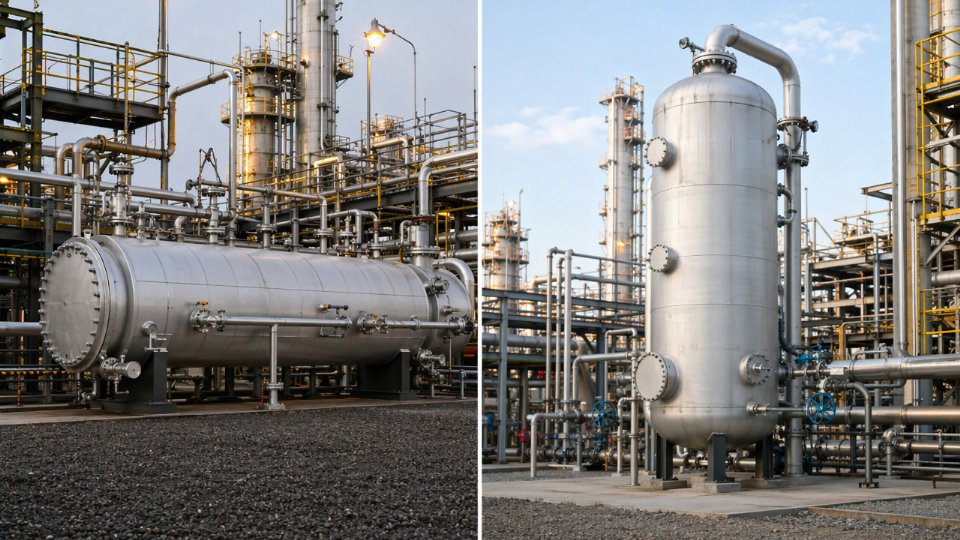
Vertical drums are sometimes preferred on tight plot plans with minimal ground footprint, or in services where liquid accumulation is genuinely low and slug risk is well-characterized. However, vertical orientation limits surge volume for a given diameter, and that constraint becomes critical when the design basis requires 10–20 minutes of liquid holdup at maximum credible release flow. Maintenance access also favors horizontal geometry: boot cleanout, internal inspection of mist eliminators, and nozzle maintenance are all easier to execute on a horizontal vessel at grade than on a vertical drum elevated on a skirt.
Does an acid gas KO drum always require post-weld heat treatment?
ASME VIII Div.1 sets mandatory PWHT thresholds based on wall thickness and P-number grouping — for carbon steel P-1 material, that threshold is typically nominal wall thickness above 1.5 inches, though exact values depend on material specification and the applicable edition of the Code. So a thin-wall vessel could theoretically be exempt under the Code’s mechanical rules alone.
In sour service, that exemption rarely survives scrutiny. NACE MR0175/ISO 15156 imposes hardness limits — 22 HRC maximum for carbon and low-alloy steels in H2S-containing environments — and heat-affected zone hardness on carbon steel welds without PWHT frequently exceeds this limit regardless of wall thickness. In practice, most fabricators and third-party inspectors treat PWHT as effectively mandatory for any carbon steel acid gas KO drum with P-1 base material. The exception worth knowing: austenitic stainless steel construction (304L, 316L, or duplex grades selected for specific corrosion environments) is not subject to PWHT requirements under NACE MR0175, though sensitization risk during welding requires controlled heat input and proper filler selection.
PWHT is not required by ASME VIII Div.1 for all wall thicknesses of carbon steel pressure vesselsTrue
ASME VIII Div.1 mandatory PWHT thresholds are thickness-dependent for P-1 carbon steel materials; however, sour service hardness requirements under NACE MR0175/ISO 15156 make PWHT practically necessary in most acid gas applications regardless of whether the Code's thickness threshold is reached.
What level instrument technology is most reliable for H2S-containing liquid service in a KO drum boot?
Guided-wave radar (GWR) has become the preferred technology for most acid gas KO drum boot applications, and for good reason. It is largely immune to fluid density changes caused by varying amine concentration or condensate composition, it has no moving parts to foul, and its output is stable under the vapor pressure fluctuations common in flare system upsets. GWR transmitters are available with SIL 2 certification from multiple manufacturers, which matters when the level signal feeds a high-level shutdown interlock on the drain pump or emergency blowdown system.
Differential pressure transmitters remain a viable alternative, particularly where a redundant measurement is required for SIL voting logic, but they are sensitive to calibration drift when the liquid density shifts — a real risk when amine carry-over changes the fluid composition during an upset. Displacer-type instruments work in clean services but are problematic in acid gas boots: fouling from amine degradation products, iron sulfide scale, and hydrocarbon tars coats the displacer and introduces significant measurement error. If displacers are already installed from a legacy design, plan for frequent calibration checks and budget for replacement.
How do I specify liquid surge volume when relief flow rate is uncertain at early FEED stage?
Uncertainty at FEED is normal, but it is not a reason to defer the surge volume question. The conservative approach is to identify the worst credible simultaneous relief scenario — typically the largest single relief device plus any background condensation load — and size holdup for at least 10 minutes at that combined flow rate. Where multiple credible simultaneous releases exist and the flare network serves a large section of the plant, 15–20 minutes is a more defensible basis and gives operations time to respond before a high-level trip forces an emergency drain.
When flow data is genuinely absent, use the flare header design capacity as the liquid loading surrogate and apply a liquid-to-vapor entrainment fraction from analogous services — typically 5–15 vol% liquid in the relieving stream for amine unit upsets, though this range depends heavily on upstream separator efficiency and the specific relief scenario. Document the assumptions explicitly in the vessel data sheet. Undersized surge volume is one of the failure modes that only becomes visible during an actual plant emergency, which is exactly the wrong time to discover it.