
Specifying process vessels for the separation and heat-recovery train downstream of a naphtha cracker is where most schedule slippage and cost overruns actually originate — not in the furnace section, where everyone focuses. A quench oil tower running at the wrong design pressure, a dilution steam separator with insufficient residence time, or a transfer line exchanger ordered against a generic datasheet rather than a cracked-gas fouling profile will surface as unplanned shutdowns within the first operating year. The financial exposure is real: a single forced outage on an integrated ethylene complex can idle downstream polymer units simultaneously, compounding lost production far beyond what any vessel price difference could justify.
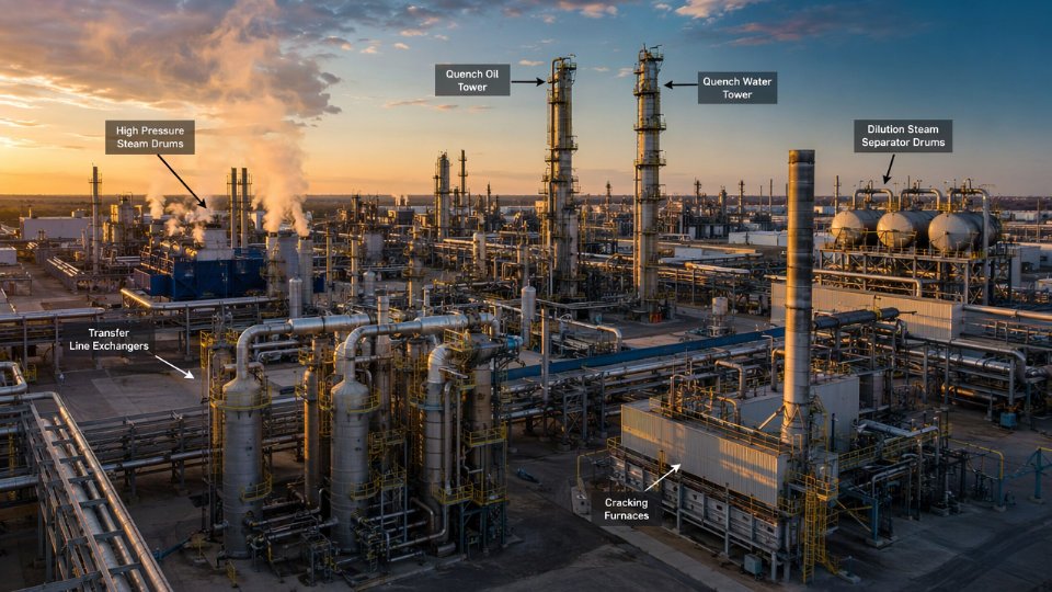
In an integrated naphtha cracker complex, the critical post-cracking vessels — transfer line exchangers, quench oil towers, and dilution steam separators — must be specified to handle cracked-gas inlet temperatures of 800–870°C, tower operating pressures of 0.3–0.8 MPag, and separator residence times of 3–5 minutes; procurement boundaries between the EPC contractor, licensor, and vessel fabricator must be fixed before FEED exit, because late scope shifts on these items carry the longest lead-time and re-engineering penalties.
What makes this portion of the plant genuinely difficult is not any single vessel in isolation — it is the interdependency. The transfer line exchanger sets the thermal load profile for everything downstream; the quench oil tower overhead vapor temperature near 100°C determines where condensate first appears in the separation sequence; the dilution steam separator drum geometry governs the water balance that feeds back into furnace operation. Get one of those relationships wrong in the datasheet stage and the correction does not stay local.
Transfer Line Exchangers: Materials, Tube Bundle Configuration, and Fabrication Specification Checkpoints
The transfer line exchanger sits at the most thermally brutal point in any naphtha cracker. Cracked gas leaves the radiant coil at 800–870°C and must be cooled to roughly 350–450°C within milliseconds — not seconds — to arrest secondary reactions that would otherwise convert ethylene into unwanted heavies and coke. Simultaneously, the shell side must generate high-pressure steam at 10–13 MPag. Both functions are non-negotiable, and both drive geometry decisions that procurement teams cannot defer to the fabricator’s standard catalog.
Why Dual Function Forces Non-Standard Geometry
The millisecond quench requirement means tube-side flow velocity, tube diameter, and bundle length are calculated together as a reaction-quench problem, not a conventional heat-transfer problem. Shorter tubes with high gas velocity minimize residence time; that conflicts with the shell-side steam generation duty, which favors longer tubes for better steam drum circulation ratios. The design is a compromise settled by the licensor’s proprietary kinetics, and any deviation — longer tubes to save cost, larger tube OD to ease fabrication — shifts the secondary cracking equilibrium. Procurement teams should treat licensor-specified tube geometry as a hard constraint, not a negotiating variable.
Tube Material: Why 25Cr-35Ni-Nb Alloy Is Not Interchangeable
Tube-side inlet temperatures of 800–870°C eliminate carbon steel and low-alloy options immediately. The industry-standard choice is a high-alloy austenitic grade, typically in the 25Cr-35Ni range with niobium stabilization — HP-Nb or equivalent centrifugally cast alloy for linear TLE designs, or wrought equivalents for smaller-bore hairpin configurations. The shell operates at lower temperatures and is typically carbon steel, occasionally with a refractory castable lining on the inlet cone where cracked gas impinges.
Tube-side surface finish has a direct operational consequence that is underappreciated in RFQ packages. A smoother internal finish — Ra below roughly 1.6 µm — measurably slows coke deposition kinetics on the tube wall. This extends decoking intervals from the low end of 30–45 days toward 60–90 days, depending on feedstock heaviness and coil outlet temperature. Specifying surface finish in the purchase order is cheap; discovering it was omitted during a forced early decoking shutdown is not.
Bundle Configuration: Linear Versus Hairpin, Forced Versus Natural Circulation
Linear (single-pass, straight-tube) TLEs dominate large-scale crackers — typically units above 300,000 tonnes per year ethylene capacity — because they accommodate the large tube counts needed for high gas throughput and allow full bundle extraction for decoking and inspection without breaking the steam-drum piping. Hairpin TLEs appear more often in smaller crackers or in retrofit situations where plot space is constrained. They offer a compact footprint but create access complications for mechanical decoking tools.
Steam-side circulation adds another decision layer. Natural-circulation arrangements tie the TLE shell to an elevated steam drum via downcomer and riser piping; the steam drum elevation must be sufficient to drive circulation at the required steam quality. Forced-circulation designs use a pump, which adds a rotating equipment dependency but allows more flexible plot layout. For new integrated complexes, natural circulation remains the more common choice because it eliminates pump reliability risk at a point in the plant where any unplanned outage cascades into furnace shutdown.
Fabrication Specification Checkpoints
Procurement documents for TLEs should reference ASME Section VIII Division 2 or the applicable national pressure vessel standard explicitly — Division 2’s design-by-analysis route is frequently required to justify the shell wall thickness at 10–13 MPag steam pressure without excessive conservatism. Key checkpoints to build into the RFQ and subsequent QC hold points:
- Tube-to-tubesheet joint qualification by mock-up weld procedure, strength-welded with seal weld, tested per ASME Section IX
- Post-weld heat treatment of the tubesheet-to-shell weld seam documented by calibrated thermocouple records, not pyrometer estimates
- Hydrostatic test at 1.3× design pressure on both shell side and tube side, conducted separately with witnessed inspection
- Inlet cone refractory dry-out procedure specified before first hot commissioning — skipping this step causes spalling that blocks tubes within weeks
Operational warning: Tube-to-tubesheet joint failures in TLEs rarely announce themselves with an obvious leak. The first symptom is often a slow contamination of boiler feedwater with hydrocarbon traces, which is detected at the steam drum blowdown analysis. By the time this is visible, the joint has typically been leaking long enough to have already caused localized overheating of adjacent tubes.
Spare Bundle Strategy and Lead Time Planning
TLE tube bundles fabricated from HP-Nb alloy centrifugal castings carry fabrication lead times of 18–28 weeks under normal foundry loading conditionsTrue
Centrifugal casting of high-alloy HP-Nb tubes requires specialized foundry capacity that is not widely available; combined with tube machining, tubesheet boring, and QC hold points including PWHT and hydrotest, 18–28 weeks is a realistic and commonly quoted range from specialty fabricators in Europe, Japan, and China's certified shops.
That lead time range assumes foundry slots are available at the time of order. During peak refinery and petrochemical capital cycles, the realistic number can stretch toward 32–36 weeks from qualified vendors. For an integrated ethylene complex on a tight schedule, this means spare bundle orders should be placed during or immediately after detailed engineering — not after mechanical completion of the primary bundle. The procurement case is straightforward: a spare bundle held in warehouse costs roughly 8–12% of the primary bundle price annually in carrying cost; a cracker furnace sitting idle waiting on a replacement bundle costs multiples of that figure per day, depending on plant capacity and regional ethylene margin.
A practical approach used on multi-furnace complexes is to order one spare bundle per every three to four furnace TLEs, sized and configured to the same specification. This provides coverage without tying up excessive capital, provided the bundle dimensions are standardized across the furnace train — a design coordination point worth raising with the licensor at FEED stage, not during detailed engineering.
Quench Oil Tower and Quench Water Tower: Column Internals, Fouling Mechanisms, and Vendor Scope Delineation
The quench oil tower (QOT) and quench water tower (QWT) sit immediately downstream of the transfer line exchangers and together handle the bulk of sensible heat removal before cracked gas reaches the wet-end compressors. They are almost always bid as separate column packages, and the scope boundary between the column vendor and the EPC contractor is one of the most contested items in any ethylene project procurement schedule. Getting that boundary wrong costs time — and typically surfaces as a dispute during mechanical completion.
Quench Oil Tower: Function, Internals Selection, and Operating Constraints
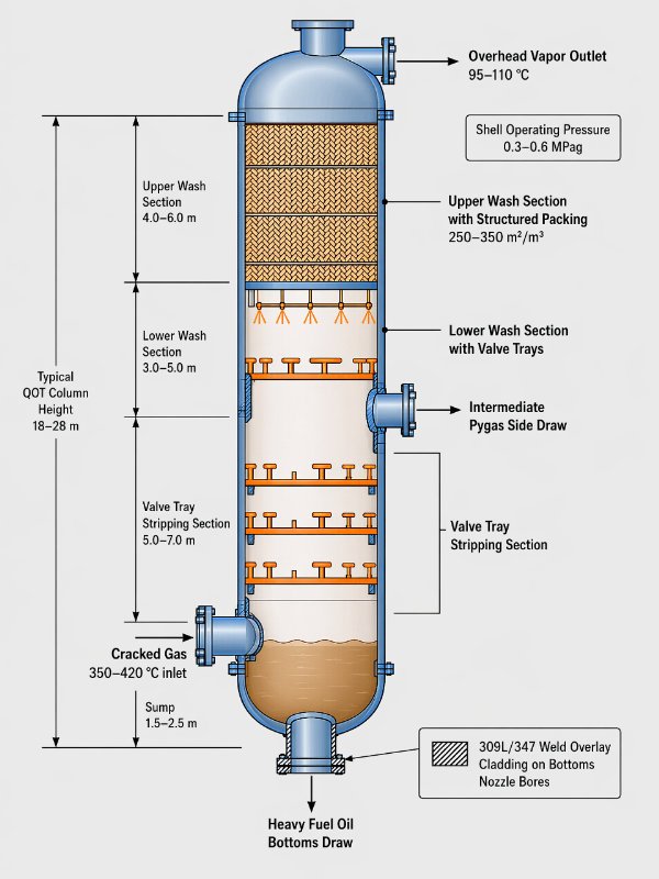
The QOT accepts cracked gas at roughly 350–420°C (depending on TLE outlet performance and cracking severity) and cools it to approximately 95–110°C overhead through direct contact with circulating quench oil. Two product streams draw off simultaneously: a heavy fuel oil fraction from the column bottoms and pyrolysis gasoline (pygas) from an intermediate draw. This dual-drawoff requirement sets the tray-versus-packing decision.
Structured packing — typically metal gauze or sheet-metal corrugated packing with 250–350 m²/m³ specific surface area — dominates the upper wash section for one practical reason: the vapor-liquid traffic at low liquid rates makes tray efficiency poor, and structured packing delivers adequate separation with significantly lower pressure drop. Lower pressure drop translates directly to lower cracked gas inlet pressure, which matters when the upstream furnace hydraulics are already tight. The lower wash and stripping sections may retain valve trays where liquid loading is heavier and fouling risk is more manageable.
Operating pressure in the QOT column shell typically runs 0.3–0.6 MPag, and the bottoms temperature can reach 170–200°C under heavy fuel oil accumulation. Specifying shell material for that bottoms zone requires attention: sulfur-bearing quench oil combined with elevated temperature pushes the corrosion allowance requirement up, and weld overlay cladding with 309L/347 stainless is common on nozzle bores and bottom head internals facing the hot residue zone.
Quench Water Tower: Coalescing Internals and Carryover Consequences
The QWT takes overhead vapor from the QOT at roughly 95–110°C and cools it further to 38–45°C using circulating quench water, recovering dilution steam condensate in the process. The critical design requirement here is not mass transfer — there is little fractionation happening — but droplet separation. Hydrocarbon carryover into the compressor suction knockout drum is the failure mode that matters. Even modest carryover, say 50–100 ppm by weight of liquid hydrocarbons entering the compressor suction, accelerates fouling in the compressor first-stage impeller channels and can trigger an unplanned shutdown within weeks rather than months.
Coalescing internals — wire mesh pads, vane-type mist eliminators, or structured fiber-bed coalescers depending on droplet size distribution — are therefore non-negotiable in the QWT overhead section. The vendor selection specification should explicitly state the required carryover limit and the droplet separation efficiency basis, not leave it as a generic “demisting” requirement.
Fouling Mechanisms and Their Material Implications
Polymerization foulant is the dominant issue in the QOT packed sections. Dienes and styrene in the cracked gas undergo thermally-driven oligomerization at the liquid film surface, depositing a tar-like polymer that progressively occludes packing channels. Operating teams typically see pressure drop across the packed bed rise 15–40% over a run cycle of 18–36 months, depending on feed composition and wash oil circulation rate. Some licensors address this with a dedicated online wash oil injection point at the packed bed top; specifying the nozzle and distributor as part of column vendor scope is worth the argument.
In the QWT, the fouling character shifts. Emulsion formation between condensed hydrocarbons and the recirculating quench water creates a persistent rag layer that can accumulate at liquid draw nozzles. Combined with the pH drop from dissolved CO₂ in the overhead vapor, under-deposit corrosion on carbon steel surfaces in the lower QWT section is a real risk. Carbon steel with a 3–4 mm corrosion allowance is common at less aggressive pH ranges (above 6.5), but if the operating pH consistently falls below 6, austenitic stainless cladding or solid 304L construction for the bottom head and lower shell courses becomes the economically correct decision once you price in an unplanned reline.
Structured packing always outperforms valve trays in quench oil tower upper sections regardless of operating conditionsFalse
Structured packing is preferred at low liquid-to-vapor ratios typical of upper wash sections due to lower pressure drop and better wetting efficiency. However, at high liquid loading rates or where fouling risk is severe, valve trays may be operationally more maintainable. The choice depends on specific vapor-liquid traffic, fouling severity, and maintenance access requirements — not a blanket rule.
Vendor Scope Delineation: Where the Column Package Ends
A well-written vendor scope for either column should include: the complete fabricated shell with all process nozzles, manways, and instrument connections; internal support rings, draw trays, distributor pipes, bed limiters, and packing or tray assemblies; the support skirt with anchor bolt template; and all access platforms and ladders to the extent they attach directly to the shell structure.
What typically stays with the EPC: pumparound cooler circuits and their piping, recycle pump suction and discharge headers, all instrumentation and control valve installations beyond the nozzle face, and any interconnecting piping between the QOT and QWT. The pumparound coolers are particularly important to keep in the EPC scope — their hydraulic design depends on overall heat integration optimization that the column vendor cannot control. Specifying them as part of the column package frequently leads to scope gap disputes at detail design.
Inspection and Testing Checkpoints
Shell plate impact testing per ASME VIII or the applicable local pressure vessel code should be specified for any course operating below 10°C ambient or handling notch-sensitive service — both conditions that apply to QWT bottom sections in colder climates. Weld overlay clad bonding examination for the QOT bottoms service should follow ASME Section IX procedure with 100% ultrasonic bond integrity testing of the clad surface, not just spot checks.
Packing support grid load testing at 1.5× design load (accounting for flooded-bed liquid hold-up during an upset) is a checkpoint that procurement teams frequently omit from the ITB and then dispute after fabrication is complete. It is far simpler to specify it upfront than to negotiate it into the inspection and test plan at the factory acceptance stage.
Dilution Steam Generation and Recovery Vessels: Process Duty, Drum Sizing Basis, and Procurement Package Content
The dilution steam system sits between the furnace feed preparation section and the cracking coils themselves, yet it generates some of the most quietly complicated vessel procurement decisions in an integrated ethylene complex. Its core purpose is thermodynamic: injecting steam alongside liquid naphtha feed reduces the hydrocarbon partial pressure inside the radiant coil, which suppresses coke deposition rates and extends run length between decoking cycles. Typical steam-to-hydrocarbon ratios run 0.3:1 to 0.6:1 by weight, varying with feedstock heaviness and furnace design. Get that ratio wrong—or supply steam of inadequate purity—and coke laydown accelerates, coil skin temperatures climb toward metallurgical limits, and the furnace comes offline weeks ahead of schedule.
What the Recovery Loop Actually Contains
The condensate-recovery side of the dilution steam circuit involves at minimum three vessel categories, and EPC contractors frequently omit one or two of them from the furnace vendor scope, leaving a gap that only surfaces during detailed engineering.
Flash drums receive condensate collected from the quench water circuit and process drains. Operating pressure is typically near-atmospheric to 0.5 MPag, with temperatures in the 120–160°C range depending on where the condensate originates. Their job is a rough first separation—flashing off dissolved light hydrocarbons and non-condensables before the water stream advances further.
Dilution steam generators (DSGs) are the heat-exchange vessels that vaporize the recovered and treated condensate into the steam actually injected at the furnace. Waste-heat DSGs use high-pressure steam or hot process streams as the heating medium; fired DSGs are a separate procurement category entirely and typically fall under the furnace vendor’s scope. Waste-heat units operate with shell-side steam generation in the 0.5–2.0 MPag range for dilution duty—significantly lower pressure than the HP steam circuit—and tube-side heating medium temperatures depend on the available waste-heat source. Shell material is usually carbon steel or low-alloy steel; the choice depends on dissolved oxygen levels in the condensate, which is the leading corrosion driver.
Polishing drums (sometimes called dilution steam separators or deaerator drums depending on the licensor’s terminology) do the final quality check: removing residual liquid droplets and ensuring vapor quality before the steam enters the furnace manifold. These are the vessels where the L/D ratio and demister specification matter most.
Drum Sizing Basis: Where the Numbers Come From
Residence time of 3–5 minutes governs the condensate flash drum and the polishing drum sizing. The lower end of that range applies when the feed is relatively clean and phase separation is straightforward; the upper end applies when the condensate carries suspended fines or emulsified hydrocarbons that slow droplet coalescence. L/D ratios of 3:1 to 5:1 are standard, with longer vessels preferred when vapor velocity must be kept low to avoid re-entraining the liquid phase—typically when operating below 0.3 MPag.
Demister pad selection depends on droplet size distribution. Knitted wire mesh pads (150–200 mm depth, wire diameter 0.1–0.28 mm) handle general duty. Where the liquid load is higher or carries fine hydrocarbon contamination that would blind wire mesh, vane-pack separators with a wider drainage channel are the better specification. Undersizing the demister causes carryover into the furnace; even small slugs of liquid condensate hitting a hot radiant coil generate localized thermal shock and accelerate tube cracking.
Water Quality: Why It Dictates More Than Chemistry
Boiler feedwater quality requirements for dilution steam are stricter than most procurement teams anticipate, because the steam contacts the furnace coil interior directly.
Silica carryover from dilution steam drums deposits on furnace coil internals, building an insulating layer that elevates tube metal temperatures and can cause premature coil failure even when bulk process conditions appear normal.True
Steam-side silica volatility is well established in boiler and steam generator practice; at the low pressures typical of dilution steam generation, silica solubility in steam is lower than in high-pressure boiler steam, making carryover a real risk when feedwater silica is not controlled below 0.02–0.05 mg/L depending on operating pressure.
Conductivity limits for dilution steam condensate typically target below 0.5 µS/cm after polishing, and dissolved oxygen below 7 µg/L. These numbers drive internal specification decisions: carbon steel drums may require internal epoxy-novolac coating or stainless steel cladding on wetted surfaces, and any stagnant zones or dead legs in the vessel nozzle arrangement become corrosion initiation sites. The procurement specification must address this explicitly—a drum fabricated to the mechanical data sheet but ignoring internal surface treatment will fail corrosion inspection within a single operating cycle.
Defining the Procurement Package Boundary
A complete dilution steam package, as a standalone procurement lot, should include the flash drum, polishing separator drum, waste-heat DSG (if applicable), all interconnecting trim piping within the battery limit, level instruments, and relief devices. The battery limit against the furnace vendor is normally defined at the steam supply nozzle entering the furnace’s dilution steam header—everything upstream is in the vessel package scope.
Where EPC contractors frequently blur this line: the deaerator, if present, may be bundled with the plant’s utility steam system rather than the dilution steam circuit. Clarify this in the invitation to tender. Leaving it ambiguous produces two vendors each assuming the other is supplying it, which is a commissioning-phase discovery no project schedule can absorb cleanly.
Primary Fractionator Design Considerations: Feed Conditions, Tray-Versus-Packing Decisions, and Column Fabrication Standards
The primary fractionator sits immediately downstream of the quench oil system and receives one of the most demanding feed streams in the entire post-cracking train. That feed is mixed-phase: cracked gas carrying entrained condensate, heavy pyrolysis fuel oil droplets, and a vapor fraction spanning roughly C2 through C9+ hydrocarbons. The boiling range across this mixture can exceed 300°C. Unlike a conventional distillation column where the feed enters at a single well-defined phase condition, the primary fractionator must simultaneously perform rectification of lighter fractions in its upper sections and direct-contact heat exchange in its lower wash section — two duties that pull internal selection in opposite directions.
Feed Conditions and the Direct-Contact Heat Exchange Challenge
The lower section of the column functions less like a conventional stripping section and more like a wash zone. Heavy aromatic compounds — naphthalene, indene, anthracene precursors — arrive with the feed and will foul any internals that create stagnant liquid holdup or narrow flow paths. Coke precursors deposit on surfaces that run too cool or trap liquid, and the fouling rate accelerates if the bottom temperature control drifts. Bottom temperatures in this zone typically run 160–220°C depending on cracker severity and feedstock composition; higher-severity operation shifts the distribution toward lighter products but also increases the coke precursor load.
This is why the lower wash section almost universally uses open-geometry internals — grid packing or shed decks, sometimes called shower decks. Grid packing offers a surface area of roughly 30–70 m²/m³ (depending on grid pitch and corrugation geometry) while presenting virtually no horizontal liquid trapping surface. Shed decks accomplish the same with even lower pressure drop. Attempting to install structured packing or valve trays in this zone is a procurement error that typically manifests within one to three months as plugged internals, rising pressure drop, and an unplanned shutdown.
Upper Section Internal Selection: Trays Versus Structured Packing
Above the wash zone, where the stream is cleaner and lighter fractions are being separated, the design decision becomes genuinely competitive. Sieve trays are the traditional choice — robust, well-understood, straightforward to replace during a turnaround. For columns where the vapor load varies significantly (seasonal feedstock swings, different severity modes), valve trays offer a wider operating range. Structured packing in the upper fractionating sections can improve separation efficiency and reduce column height, but the capital cost premium over trays is only justified if height is the binding constraint, for example when the column diameter is already fixed by vapor load and height drives transportation or foundation cost.
Tray efficiency assumptions for wide-boiling mixtures like this one are conservative — typically 40–60% Murphree efficiency for the lighter C4–C6 separation range — which increases the theoretical stage count and therefore column height compared to a narrow-cut column.
Column Diameter and Height Sizing Realities
Vapor load from the cracked gas flow rate drives column diameter. For world-scale naphtha crackers processing 300,000–800,000 tonnes per year of ethylene equivalent, primary fractionator diameters typically fall in the 3–6 meter range. The lower end applies to smaller complexes or columns that receive partially pre-fractionated feed; the upper end is governed by hydraulic flooding limits at the design vapor velocity, which depends on tray spacing (typically 500–600 mm for the fractionating section) and the liquid-vapor density ratio at operating conditions.
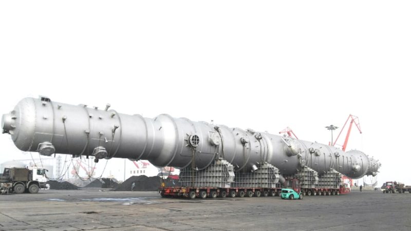
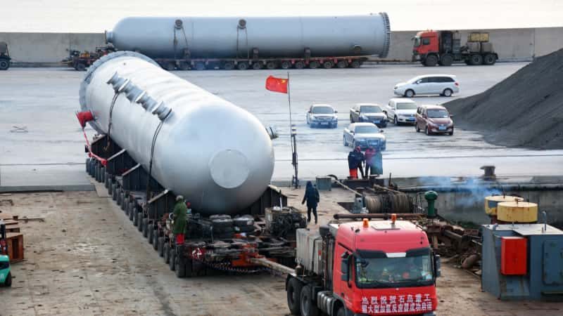
Column height follows from the number of theoretical stages, tray spacing, and the physical height of the wash section. Total tangent-to-tangent heights of 30–50 meters are common. That combination of diameter and height places the primary fractionator squarely in the category of equipment that challenges road transport limits in most jurisdictions.
Fabrication Standards and Code Selection Impact
Primary fractionators built for projects with U.S. or international EPC governance are typically designed to ASME VIII Division 1 for lower-pressure applications or Division 2 when pressure or wall thickness optimization justifies the additional engineering and documentation burden. Division 2 allows higher allowable stresses, which translates directly to reduced wall thickness on a large-diameter shell — the cost saving on plate material for a 5-meter-diameter column can offset the additional analysis cost, though this crossover point depends on material grade, design pressure, and the specific fabricator’s engineering overhead rate.
European projects under PED (Pressure Equipment Directive) follow EN 13445 as the harmonized standard, with notified body involvement for Category III and IV equipment — which a column of this size and service will almost certainly require. For projects executed under Chinese EPC contracts or with Chinese-domestic shop fabrication, GB 150 applies. GB 150 and ASME VIII are not directly interchangeable: pressure ratings, weld joint efficiency factors, and NDE requirements differ in ways that affect both wall thickness calculations and fabrication cost. A procurement team switching codes mid-project to accommodate a lower-cost fabricator must re-verify all pressure calculations, not merely accept a reissued drawing.
Switching from ASME VIII Div. 1 to GB 150 mid-project requires full recalculation of shell wall thickness and weld joint efficiencies, not just a drawing re-stamp.True
The two codes use different allowable stress bases, weld joint efficiency tables, and NDE acceptance criteria. A direct drawing re-stamp without recalculation creates an unverified design that most EPC quality systems will reject during document review.
Skirt Design, Modular Shipping, and the Fabrication Location Decision
A 5-meter-diameter, 40-meter-tall fractionator weighs 200–450 tonnes depending on wall thickness, internals, and insulation. Road transport of a single-piece shell that large is possible in some regions with wide-load permits, but in landlocked plant locations or regions with weak road infrastructure it becomes the cost driver that forces a field fabrication decision. Field fabrication introduces weld quality control challenges — environmental exposure, workforce qualification variability, NDE logistics — that shop fabrication largely eliminates.
The practical procurement decision usually comes down to three variables: distance from the fabrication shop to site, available port and road infrastructure, and whether the EPC schedule allows the longer lead time that field fabrication typically requires (field erection adds 4–10 months compared to a shop-built and shipped unit, depending on column complexity). Modular shipping — fabricating the column in flanged sections, each within road-transport limits — is a middle path that preserves much of the shop fabrication quality advantage while keeping individual piece weights manageable. The flange joints between sections require careful design to ensure gasket integrity under the column’s operating pressure and thermal cycling, and those flanges add cost that the procurement estimate must account for from the outset.
Coalescing Separators and Suction Drums: Sizing, Internals Specification, and Integration with Cracked Gas Compressors
The vessel immediately upstream of the cracked gas compressor is one of the least glamorous pieces of equipment in the post-cracking train — and one of the most consequential to get wrong. Liquid carryover into a high-speed centrifugal or reciprocating cracked gas compressor generates liquid slugs that erode impeller blades, cause thrust bearing failures, and can produce overpressure transients in the suction drum itself if a large slug collapses suddenly on the suction side. Unplanned compressor trips in an ethylene plant cascade fast: you lose separation train throughput, flare systems absorb the gas, and you may face a full train restart that costs anywhere from several hours to multiple days depending on how cold the cold box has gone. The suction drum and coalescing separator package is genuinely safety-critical infrastructure, not a utility vessel.
Sizing Methodology: Where Most Procurement Specs Fall Short
Sizing starts at the inlet nozzle. Inlet momentum flux — defined as ρv² — should be controlled below roughly 1,500–3,000 kg/m·s² depending on whether the incoming flow is two-phase or vapor-dominated at that stage; higher inlet momentum throws liquid droplets onto the vessel wall and re-entrains them before settling can occur. Nozzle sizing often drives a larger drum diameter than the settling calculation alone would suggest, and this conflict between nozzle velocity limits and vessel aspect ratio is where undersized drums typically originate.
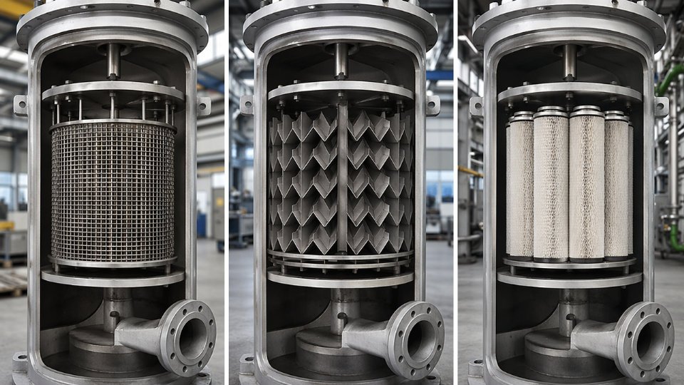
Settling section residence time should be calculated for the actual liquid loading at design turndown, not only at full throughput. For typical first-stage suction drums on naphtha crackers, residence times of 1.5–4 minutes are common, depending on liquid rate variability and whether condensate recovery is routed continuously or in intermittent drain cycles. Coalescer element face velocity limits are not universal: wire mesh pads operate effectively in the 0.03–0.06 m/s range in relatively clean service, but cracked gas condensate carries polymerization foulants — primarily heavy C5+ oligomers — that blind wire mesh within weeks in severe cases. Vane packs tolerate higher liquid loads and resist fouling better but carry a higher pressure drop penalty, typically 0.5–2.0 kPa versus 0.1–0.5 kPa for wire mesh, depending on geometry and vapor velocity. High-efficiency coalescing cartridges offer the best droplet separation down to 1–3 µm but require the lowest face velocity and the most rigorous fouling protection upstream.
Internals Selection: Matching the Element to the Service Reality
Wire mesh is appropriate when the condensate rate is low and predictable, the upstream quench system is performing well, and online wash capability is not required. Vane packs are the more defensible choice for first-stage suction drums where upstream quench tower performance is uncertain or where liquid slugging events are plausible during start-up and upset conditions. Coalescing cartridges belong in later compression stages where the gas is drier and the separation duty is fine mist removal, not bulk liquid knockout.
Wire mesh demisters are interchangeable with vane packs in cracked gas suction drum service without process penalty.False
Wire mesh and vane pack internals differ significantly in liquid load tolerance, fouling resistance, and pressure drop. In cracked gas service with heavy hydrocarbon condensate, substituting wire mesh for a vane pack design without re-evaluating face velocity, drain capacity, and fouling interval can lead to premature blinding and compressor liquid carryover events.
Material Requirements and Hydrogen Embrittlement Considerations
Shell material for first- and second-stage suction drums is typically carbon steel — ASME SA-516 Gr. 70 is common — but the internal environment is not benign. Dilute carbonic acid and trace H₂S in the condensate phase drive pitting corrosion on carbon steel surfaces, so internal wetted components, demister supports, drain sumps, and nozzle liners are normally specified in 304L or 316L stainless. At higher compression stages — third stage and above, where suction pressures reach 2–5 MPag on a typical multi-stage cracked gas compressor — hydrogen partial pressure rises enough that high-strength fasteners and any cold-worked stainless components need to be evaluated for hydrogen-assisted cracking. This is often handled by restricting internal fastener hardness to Rockwell C22 maximum and avoiding cold-formed 304 internals in favor of annealed material or duplex grades.
Compressor OEM Interface: Data Exchange Requirements That Fabricators Often Miss
The cracked gas compressor vendor will impose nozzle load limits — three forces and three moments at each suction and discharge nozzle — that the vessel fabricator must satisfy with the piping and support design. Vessel foundation stiffness requirements, which affect compressor shaft alignment under thermal growth, are sometimes defined by the compressor OEM as a minimum support natural frequency to avoid resonance with compressor running speed. Fabricators who treat the suction drum as a standalone vessel scope and hand off to the piping contractor without coordinating these interface data packages create problems during commissioning: soft-foot corrections, nozzle rework, and vibration surveys that delay compressor run-in. The procurement package for suction drums should require the fabricator to participate in a documented vendor interface meeting with the compressor OEM before nozzle orientation and support design are finalized.
Heat Exchanger Selection and Specification Across the Post-Cracking Train: Shell-and-Tube, Air-Cooled, and Welded Plate Types
The post-cracking section of a naphtha cracker contains more distinct heat exchanger duties than almost any other process unit of comparable physical footprint. Getting the type selection wrong at the enquiry stage costs time twice: once when a vendor submits a technically non-compliant bid, and again when the installed unit underperforms during commissioning. A structured mapping of duties against exchanger types — before the datasheet is issued — eliminates most of that rework.
Mapping the Heat Exchanger Duties
Four duty zones dominate procurement attention in this section. Pumparound coolers on the quench oil tower handle heavy, fouling-prone liquid at 150–200°C with significant coking potential; they are high-duty, low-forgiveness pieces of equipment. Overhead condensers on the quench water tower operate at milder temperatures (typically 60–100°C) but carry dilute process water and light hydrocarbon vapor, making material selection and tube-side velocity control critical for corrosion management. Dilution steam reboilers and condensate coolers sit in a relatively clean, moderate-pressure steam/water service — the duty that most often gets under-specified because it looks routine. Interstage coolers on the cracked gas compressor handle cracked gas between compression stages at progressively higher pressures (from roughly 0.3 MPag at stage one inlet to 3.5–4.0 MPag at final stage discharge, depending on the compressor train design); liquid dropout and fouling from polymerization are real risks if skin temperatures are not controlled.
Shell-and-Tube Versus Air-Cooled for Quench Oil Service
For pumparound cooler service on the quench oil tower, the choice between shell-and-tube and air-cooled equipment hinges on three site-specific factors: cooling water availability and cost, plot space, and the plant’s fouling management philosophy.
Shell-and-tube TEMA G or H shells are commonly specified for high-viscosity quench oil duties because the longitudinal baffle arrangement reduces the number of passes and lowers the risk of dead zones where coke deposits initiate. TEMA E shells are workable in lower-fouling services but the U-bend arrangement makes mechanical cleaning impractical — a serious liability in quench oil service where annual pigging or hydroblasting is the norm. Fouling resistance values for quench oil on the tube side typically run 0.0004–0.0006 m²·K/W, depending on the crude slate processed; understating this on the datasheet directly results in undersized surface area and premature performance loss.
Air-cooled exchangers (fin-fan units) become attractive when cooling water is constrained or when the plant sits in a water-scarce region. Forced-draft configurations are generally preferred for maintainability — the fan and drive are accessible from grade — though induced-draft units offer more uniform air distribution across the bundle. The main operational risk with air-coolers in quench oil service is cold-weather viscosity increase at the tube inlet; minimum approach temperature controls and louver systems need to be specified explicitly, not left to the vendor’s discretion.
Welded Plate Exchangers: Where They Fit and Where They Don’t
Welded plate heat exchangers offer genuine advantages in dilution steam condensate cooler service: heat transfer coefficients are 3–5× higher than equivalent shell-and-tube units, footprint is dramatically smaller, and the all-welded construction handles the moderate pressures (typically below 2.5 MPag) in that service without gasketed joint risk. The limitation is mechanical: welded plate units cannot be opened for physical cleaning, which makes them unsuitable for any duty with hard-deposit fouling potential. Quench oil coolers and interstage coolers carrying cracked gas with potential for polymer deposition are the wrong applications. Misapplying a welded plate unit to a fouling service typically results in an unplanned bundle replacement within 18–36 months, depending on run length and feedstock quality.
TEMA Class Selection Logic and Cost Implications
TEMA Class R is the correct starting point for any exchanger in lethal or cyclically loaded service — including the steam-side of transfer line exchangers and any unit handling cracked gas at elevated hydrogen partial pressure. Class C is appropriate for utility exchangers in clean water or steam service where cyclic loading is absent. The cost delta between Class C and Class R on a given shell size typically runs 15–30%, depending on the material and fabrication vendor; the lead time increment is commonly 4–8 weeks. Upgrading from Class C to Class R mid-procurement — after the purchase order is placed — is far more expensive than specifying correctly at the enquiry stage, because it may trigger re-rating of nozzle loads, flange ratings, and radiographic examination requirements.
TEMA Class R automatically requires radiographic examination of all pressure weldsFalse
TEMA Class R mandates more stringent fabrication and inspection standards than Class C, but the specific NDE requirements — including radiographic examination — are governed by the applicable pressure vessel code (ASME VIII Div. 1 or 2, or EN 13445) and the fluid service category, not by TEMA class alone. The two sets of requirements must be read together on the datasheet.
Datasheet Requirements for Effective Enquiries
A heat exchanger enquiry document that generates comparable, technically compliant bids needs to fix the following parameters clearly: process fluid composition or a representative stream table, inlet and outlet temperatures and pressures for both sides, allowable pressure drop on each side (expressed as a maximum, not a target), fouling resistances with the basis for the values stated, material specifications for wetted parts including tube, shell, and nozzle materials, and the applicable design code with any supplementary requirements such as NACE MR0103 for sour service or impact test temperatures for cold climates. Leaving fouling resistance or allowable pressure drop open for the vendor to assume is the single most common cause of non-comparable bids in a multi-vendor enquiry process.
EPC Procurement Boundary Documents: How to Structure Vessel and Column Enquiry Packages for Naphtha Cracker Projects
A poorly structured enquiry package for a quench oil tower or a set of dilution steam drums does not just slow down bidding — it produces a spread of non-comparable offers, triggers weeks of clarification cycles, and in the worst cases forces late scope additions that erode the fabricator’s margin and the project’s contingency simultaneously. Getting the document set right before RFQ issue is not administrative formality; it is schedule risk management.
The Core Document Set Every Vessel Enquiry Needs
The minimum package for a non-standard pressure vessel or column in a naphtha cracker post-cracking train should contain six document types: a process datasheet (fluid composition, operating and design P/T, flow rates, fouling factors), a vessel datasheet (overall dimensions, orientation, nozzle schedule, L/D basis), a mechanical datasheet (wall thickness basis, corrosion allowance, material specifications down to weld overlay requirements), an applicable codes and standards list, an inspection and test plan with hold and witness point designations, and commercial terms including delivery point, INCOTERMS, documentation language, and data book requirements.
Omitting any one of these — particularly the ITP — routinely causes problems. Fabricators in lower-cost regions may default to their own standard ITP, which may not include radiographic examination of longitudinal seams in high-alloy sections or third-party witness for final hydrostatic test. Discovering this after purchase order award is expensive to correct.
Writing a Scope of Supply Definition That Closes Gaps
The scope section of an enquiry should enumerate what is included, not just describe the vessel. State explicitly whether the package covers internals (trays, structured packing, mist eliminators, coalescer cartridges) or whether these are owner-furnished. Define whether the vendor is responsible for nozzle orientation final confirmation, davit arm supply, earthing lug quantity and placement, and insulation support rings. Specify the surface preparation standard — typically Sa 2.5 to ISO 8501-1 for carbon steel vessels with operating temperatures below 200 °C — and the coating system by generic type if the project has not yet selected a preferred paint schedule.
A one-line scope statement reading “complete pressure vessel per attached datasheet” generates bid clarifications on every point above. A scope matrix with a Y/N/TBD column for each deliverable reduces that to near zero.
Fabrication Location and Dual-Code Compliance
Where fabrication is executed in China under GB 150 and TSG 21, with the vessel destined for a project in a jurisdiction requiring ASME Section VIII Division 1 or European PED compliance, the enquiry must address this explicitly at RFQ stage — not during drawing approval. Dual-stamping (ASME U-stamp applied at a China-based ASME Certificate Holder shop) is achievable and reasonably common for large column shells, but it requires the AI (Authorized Inspector) to be engaged from material receipt, not from hydrostatic test. Build that requirement into the ITP and confirm the fabricator holds a current U-stamp certificate before short-listing.
A China-fabricated vessel can carry a valid ASME U-stamp if the shop holds a current ASME Certificate of Authorization and an Authorized Inspector witnesses fabrication from material traceability through final test.True
ASME's certification program is open to shops globally; the U-stamp is issued based on compliance with ASME Section VIII rules regardless of country, provided an AI employed by an ASME-accredited inspection organization is present throughout fabrication.
Long-Lead Release Strategy
Transfer line exchangers and large-diameter primary fractionators — columns above roughly 4 m diameter with alloy-clad shells — carry fabrication lead times that frequently run 18 to 30 months depending on plate mill allocation and shop loading. These vessels must be released for fabrication before detailed engineering is complete. The minimum information needed to issue a defensible purchase order without complete drawings: confirmed design P/T envelope, shell material grade, overall height and diameter within ±5%, nozzle count and approximate schedule, applicable code edition, and delivery milestone. Fix everything else through approved-for-fabrication drawings issued within an agreed window — typically 10 to 14 weeks after PO.
Releasing on insufficient data is a risk; not releasing on time is a larger one.
Vendor Qualification Criteria
Short-list criteria for naphtha cracker vessel suppliers should include: current ASME U-stamp or PED Notified Body certification appropriate to the delivery jurisdiction; documented project references for vessels in cracked gas or high-temperature hydrocarbon service (not just generic refinery vessels); a third-party-audited quality management system at minimum equivalent to ISO 9001 with documented weld procedure qualifications for P91, 321H, or Incoloy 825 if high-alloy work is in scope; and in-house TOFD and phased-array UT capability for thick-wall welds rather than reliance on subcontracted NDT teams whose scheduling is outside the fabricator’s control.
A fabricator who cannot provide at least two verifiable references for columns above 3 m diameter in ethylene or similar cracking service should be treated as a developmental vendor and managed accordingly — which means more inspector-hours on site, not fewer.
Quality Control, Inspection Milestones, and Non-Destructive Examination Requirements for Post-Cracking Vessels
Post-cracking vessels operate at conditions that leave almost no margin for fabrication shortcuts. A TLE handling cracked gas at 800–870°C inlet, or a quench oil tower cycling between ambient during shutdown and 200°C bottom-section service, will expose any defect in a weld, clad bond, or heat-treatment practice within one or two operating cycles. Getting the inspection hold points right before the vessel ships is the only realistic intervention window.
Critical Hold Points for High-Temperature Vessel Fabrication
The inspection and test plan (ITP) for TLEs and quench towers should distinguish between Hold points — where fabrication physically stops until the inspector signs off — and Witness points, where the fabricator must notify but can proceed if the inspector waives attendance. Conflating the two is the single most common source of ITP disputes on cracker projects.
Material certification review is the first mandatory hold. For Cr-Mo pressure parts (1¼Cr-½Mo through 2¼Cr-1Mo are typical in TLE shells), verify heat-specific MTRs against ASME SA-387 grade and class requirements, checking carbon equivalent, phosphorus, and sulfur individually — not just tensile summary. Stainless internals require positive material identification (PMI) at the fabricator’s receiving dock, not just at final inspection. One incorrect heat of material entering the shop looks identical to the correct one.
Fit-up and dimensional checks before root-pass welding are a hold point for any joint exceeding 50 mm wall thickness. Angular misalignment tolerances tighten considerably on thick-wall nozzles; the ASME VIII Div.1 alignment limits were written for average service, and clients specifying high-cycle thermal fatigue service often impose tighter values in the purchase specification.
Welding procedure qualification verification must confirm that the PQR test conditions bracket the actual production joint: same base metal P-number, same filler classification, same heat input range, and — critically for Cr-Mo — same post-weld heat treatment cycle used during qualification. A PQR performed on 25 mm plate does not automatically qualify the same procedure on 80 mm plate.
PWHT monitoring is a hold point, not a review point. The time-temperature chart from a calibrated recorder is a primary deliverable. For 2¼Cr-1Mo components, soak temperature windows are narrow (typically 690–720°C depending on specification); a chart showing a brief temperature excursion above the upper limit requires documented disposition, not silence.
Final hydrostatic test witness closes the hold sequence. Minimum test pressure multipliers and hold duration follow the applicable code, but the client should also specify leak-check criteria at all nozzle connections, particularly where clad liner interfaces are present.
NDE Method Selection for Key Weld Categories
Radiographic testing remains the default for full-penetration butt welds in pressure shells where wall thickness allows adequate radiographic sensitivity — generally below 50 mm for practical film RT. Above that range, or where geometry prevents double-wall exposure, phased-array ultrasonic testing (PAUT) provides better volumetric coverage and a permanent digital record. PAUT scan plans for nozzle-to-shell welds in TLE shells should be reviewed and approved before production welding begins, not after.
Magnetic particle testing applies to all ferritic weld surfaces after final PWHT and again after hydrostatic test, targeting hydrogen-assisted cracking and any stress-relief cracks at weld toes. Liquid penetrant testing replaces MT for austenitic stainless internals — trays, distributor rings, and downcomers — where MT is ineffective. Surface condition before PT matters: any mill scale or weld spatter left on the surface defeats the method.
Cladding and Overlay Inspection Requirements
Explosion-bonded clad plates used in quench tower shells require ultrasonic bond testing per ASTM A578, with acceptance criteria agreed before plate procurement — not after a defective plate arrives at the fabricator. Bond defects near plate edges are common; the acceptable unbonded area per ASTM A578 Level C is more generous than most petrochemical clients will accept, so the purchase specification should invoke a tighter acceptance level explicitly.
For stainless weld overlay on carbon or Cr-Mo substrates, ferrite number (FN) measurement on deposited weld metal is mandatory. FN below 3 risks hot cracking; FN above 10 reduces corrosion resistance in certain quench service environments. The target range — typically FN 4–8 — should appear in the welding procedure specification, not just in the final inspection requirement. Brinell hardness testing after PWHT on Cr-Mo pressure parts confirms adequate tempering; hardness consistently above the specified maximum suggests insufficient soak time or temperature and warrants re-treatment evaluation.
Documentation Package for Code Certification
An ASME U-stamp data book or CE-PED technical file for these vessels is not a courtesy — it is the legal basis for the pressure vessel’s service authorization. The complete package includes: heat-specific MTRs for all pressure-retaining materials; a weld map cross-referencing every joint to its WPS, PQR, and welder or welding operator qualification record; NDE reports with coverage sketches; PWHT time-temperature charts with calibration records for the furnace instrumentation; and the pressure test certificate signed by the Authorized Inspector (AI) or Notified Body representative.
A fabricator holding a valid ASME U-stamp certification has demonstrated procedural compliance to ASME requirements, but the U-stamp does not guarantee that every production vessel manufactured under that certificate meets all client-specific requirements stated in the purchase specification.True
ASME certification audits shop procedures and quality systems. Client-specific material grades, NDE acceptance levels, supplementary PWHT requirements, and inspection hold points that exceed code minimums are enforced only through the ITP and the purchase specification — not through the U-stamp process itself.
Third-Party Inspection Agency Roles and Access Rights
The TPI inspector acts under the owner’s or EPC contractor’s authorization, but operates within whatever access rights the purchase contract specifies. Fabricators sometimes restrict inspector access to completed welds only, excluding fit-up and pre-heat verification. If the contract is silent on access scope, that restriction is contractually defensible and operationally problematic. The purchase order should state explicitly that the TPI inspector has access to all fabrication stages identified as Hold or Witness points in the ITP, including raw material receiving.
Common disputes arise at three points: when the fabricator proceeds through a Hold point without notification (a serious contract breach that typically voids code stamp authority); when the client requests additional NDE beyond the agreed ITP scope mid-fabrication and the fabricator invoices for access time and rework risk; and when PWHT chart anomalies surface during final documentation review, long after the vessel has been painted and delivery is imminent. All three situations are substantially easier to manage when the ITP is negotiated and signed by both parties before the first material is cut.
Frequently Asked Questions: Naphtha Cracker Vessels, Column Procurement, and Heat Exchanger Specification
What is the typical fabrication lead time for a quench oil tower, and what drives schedule risk?
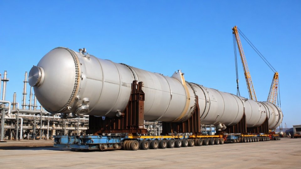
Large quench oil towers — typically 4–6 m diameter and 30–50 m tall for world-scale ethylene units — carry fabrication lead times of 36–52 weeks from purchase order to ready-for-shipment. Where that range lands depends almost entirely on three factors that have nothing to do with the vessel’s design complexity.
Plate rolling capacity is the first constraint. Shells in the 4–6 m range require heavy plate rolls that relatively few shops possess, and those rolls are often already committed months ahead. If your enquiry package reaches a fabricator whose rolling bay is scheduled through the next season, expect the upper end of that range regardless of their welding speed.
Weld overlay cladding productivity is the second. Quench oil towers typically require 316L or 317L stainless cladding on the bottom section and sometimes on tray support rings. Manual overlay runs at roughly 1–2 kg of weld metal per hour per welder; automated strip cladding is faster but demands qualified procedures and fixturing. A shop trying to run cladding manually on a large-diameter shell section while also managing structural welding on the same schedule will hit productivity walls.
Third-party inspection availability is the most underestimated risk on this list. Authorized inspection agencies with petrochemical pressure vessel experience are a constrained resource. If your project schedule requires concurrent TPI at multiple fabricators — which it almost certainly does on a full cracker equipment package — booking inspection slots early, often before purchase order, is worth a direct conversation with your AIA.
Can a transfer line exchanger be fabricated to both ASME Section VIII and GB 150 simultaneously?
Dual-code fabrication is technically feasible. It is not unusual for TLEs destined for plants in China to be specified to both codes, particularly when the end client holds a Chinese design pressure vessel license requirement while the EPC contractor’s parent specification defaults to ASME. The mechanics of doing this correctly matter. Design pressure and temperature margins are calculated under both codes independently, and the governing (more conservative) value must be taken for each parameter — you cannot cherry-pick favorable numbers from each code. Material certifications must satisfy both: a plate that meets SA-387 Gr. 22 does not automatically satisfy GB 713 Q345R, and the mill certification must explicitly cover both, or supplementary testing is required. The AIA arrangement needs written agreement from both the ASME-authorized inspector and the Chinese special equipment inspection agency before fabrication begins, not after first-article inspection. Expect dual-code execution to add 8–15% to fabrication cost and 4–8 weeks to schedule depending on how aligned the shop’s existing procedures already are with both standards.
Dual-code ASME/GB 150 fabrication always increases cost and schedule versus single-code execution.True
Each code has independent documentation, certification, and inspection requirements; satisfying both simultaneously adds coordination, testing, and AIA management overhead that has no shortcut.
What is the difference between a quench water tower and a dilution steam separator, and can they be combined?
The quench water tower sits at the battery limit of the cracking section. Its job is direct-contact cooling of cracked gas — knocking down bulk temperature, condensing heavy components, and performing a first-pass hydrocarbon-water separation. It handles the full cracked gas flow and operates at relatively low pressure, typically under 0.5 MPag, but with significant fouling and tar deposition risk at the bottom.
The dilution steam separator sits downstream in the condensate recovery loop. It receives the recovered process condensate and strips out residual hydrocarbons before that condensate is re-vaporized as dilution steam and returned to the cracking furnaces. The process duty is condensate polishing, not bulk gas cooling. Residence time requirements, vapor-liquid separation internals, and materials of construction are all different.
Combining them into a single vessel is occasionally discussed and rarely executed on world-scale units. The mass flow mismatch between the two duties typically makes a combined vessel either oversized for the separator function or undersized for the contact cooling function. On smaller crackers — below roughly 300 KTA ethylene capacity — a combined or closely coupled arrangement may be justifiable if plot space is severely constrained, but this is a process licensor decision, not a fabricator or procurement decision.
How should fouling factors be specified for quench oil service heat exchangers?
Quench oil is among the worst fouling services in petrochemical processing. Polymerization of diene-rich streams, coke precursor deposition, and thermally driven asphaltene dropout combine in ways that make TEMA fouling resistance tables a floor, not a specification. The TEMA default for heavy hydrocarbon oil service runs around 0.000352 m²·K/W on the shell side. In practice, quench oil coolers in operating naphtha crackers foul to effective resistances two to three times that value within a single run cycle, depending on furnace severity, feedstock, and quench tower operating temperature.
The correct approach is to request fouling factors from the process licensor explicitly. Most licensors maintain fouling data from their operating references and will issue project-specific values as part of the process design package. If licensor data is unavailable — which sometimes happens on revamps where the original licensor is no longer engaged — then apply a multiplier of 1.5–2.0 on the TEMA default and document the basis explicitly in the datasheet. Specifying a cleaning interval and acceptable pressure-drop rise as alarm and shutdown criteria is equally important; the fouling factor alone does not protect the exchanger if operations has no trigger to pull it for cleaning.
What fabricator certifications should be considered minimum for a world-scale naphtha cracker project?
The baseline for international projects is an ASME U-stamp with a valid certificate of authorization, meaning the shop has passed ASME’s survey within the past three years. ISO 9001 certification matters less as a standalone credential than as evidence the shop maintains a documented quality management system — auditors will look at whether the QMS is actually followed, not just whether the certificate is current.
Demonstrated high-alloy fabrication experience is non-negotiable for most post-cracking vessels. TLEs require Cr-Mo (typically 1.25Cr-0.5Mo or 2.25Cr-1Mo) with post-weld heat treatment; quench towers and fractionators may require 316L stainless cladding; some upstream vessels require nickel alloy weld overlays. A shop with a strong carbon steel record but no traceable high-alloy projects is a qualification risk regardless of their ASME status.
Third-party audit history is the most informative single document a procurement team can request. Ask for the last two client or AIA audit reports, not the fabricator’s self-assessment. Non-conformance closure rates and repeat findings tell you more about actual shop discipline than any certification document will.