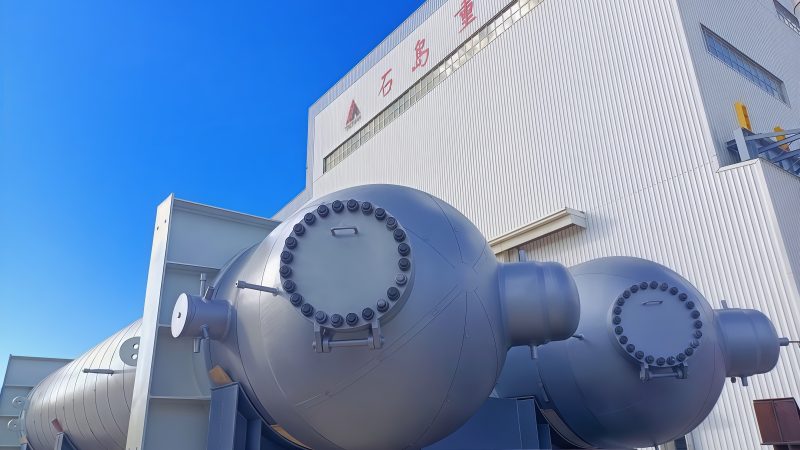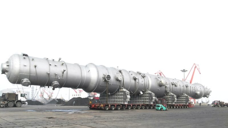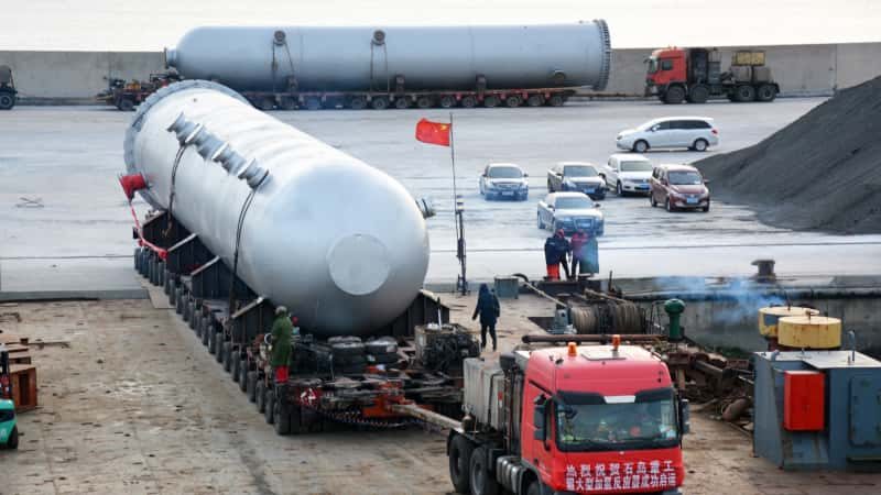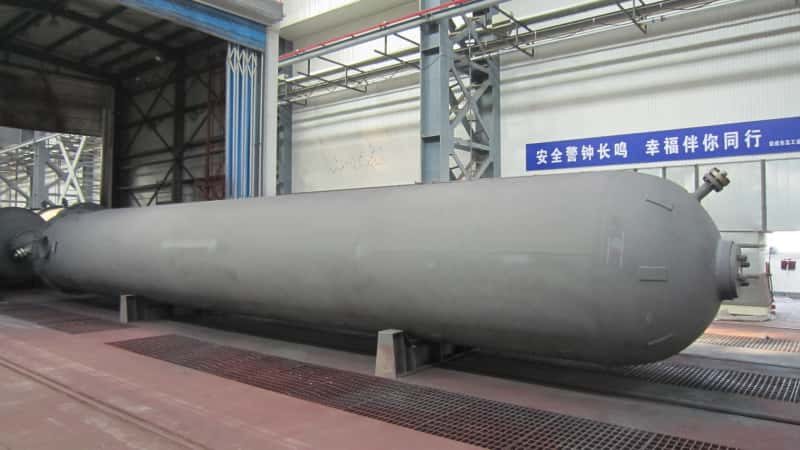

EPC project schedules slip most often not in the main process units, but in the offsite systems nobody budgets enough engineering hours to specify properly. A cooling water makeup skid lands late because the blowdown drum wall thickness wasn’t confirmed against the site’s chloride levels until week 34. A large atmospheric storage tank sits waiting for foundation work that was delayed because the soil-bearing data wasn’t tied into the vendor drawing review cycle. These are not exotic failures — they are the normal consequence of treating offsite as an afterthought. In a 200,000 BPD integrated complex, offsite systems routinely represent 15–25% of total installed cost, yet they absorb less than 10% of front-end engineering attention. That imbalance is where budget overruns and startup delays are born.
Offsite equipment in refinery-petrochemical complexes — storage tanks, cooling water exchangers, blowdown systems, flare headers, utility distribution, and wastewater treatment vessels — typically accounts for 15–25% of total installed cost but is systematically under-engineered at the FEED stage, driving procurement lead-time failures and late mechanical completion across API 650 tanks, fired equipment, and heat transfer systems.
What makes this gap particularly costly is how late it surfaces. By the time a procurement manager realizes that API 650 tanks above 10,000 m³ carry lead times of 28–52 weeks depending on plate mill availability, fabricator queue depth, and shell course inspection hold points, the project schedule has already been built around an optimistic 20-week assumption. The sections below work through each major offsite equipment category — what drives specification errors, what the realistic procurement windows look like, and where the consequence logic of getting it wrong runs directly into startup cost and operational reliability.

Atmospheric and Low-Pressure Storage Tanks: Specification Traps EPC Buyers Routinely Miss
Storage tanks look deceptively simple on a project equipment list. A line item reading “API 650 crude storage tank, 50,000 m³, fixed roof” hides a cascade of engineering decisions that, if deferred to the vendor’s discretion, will generate change orders, delay mechanical completion, or create inspection failures you won’t discover until hydrostatic testing. Lead times for large-diameter tanks commonly run 28–52 weeks from purchase order to mechanical completion, depending on plate thickness, roof type, and whether nozzle fabrication is done in-shop or field-erected. Miss the specification window early, and that range shifts hard toward the upper end.
Roof Type Is Not a Finish Detail — It Drives the Entire Fabrication Scope
Procurement teams frequently treat roof selection as an aesthetic or regulatory checkbox. It isn’t. A fixed-cone roof on a crude or intermediate stream tank requires a different nozzle schedule than an internal floating roof (IFR) on the same service — more roof nozzles for pressure-vacuum relief, gauge hatches, and foam inlets, with specific elevation requirements that affect structural ring design. An external floating roof (EFR) used on high-vapor-pressure naphtha or reformate service introduces rim seal specifications, rolling ladder rail mounts, and secondary seal requirements that materially change the fabrication package. Vendors who receive a skeleton datasheet will default to whatever minimizes their shop hours. The resulting tank may be structurally compliant with API 650 yet functionally wrong for the vapor control, firefighting, or gauging systems your instrumentation team specified separately. Reconciling that mismatch in the field costs more than fixing it in the requisition.
Corrosion Allowance: Where Cost-Cutting Creates Inspection Liability
For crude tanks and high-sulfur intermediate storage, corrosion allowance selection carries API 653 implications that extend well beyond the initial build. A 1.5 mm shell corrosion allowance might satisfy the capital cost model. In high-sulfur crude service, where bottom-water accumulation and microbial activity are routine, bottom plate wastage rates of 0.1–0.4 mm/year are realistic depending on water draw discipline and cathodic protection quality. That same tank, reinspected at a five-year interval per API 653, can trigger a mandatory bottom replacement in the first operating cycle if the original allowance was undersized. Specifying 3–4 mm on bottom plates for aggressive service costs relatively little at fabrication and avoids a full-tank outage and bottom reline inside the first decade. Procurement managers optimizing unit cost on this line item routinely create a larger lifecycle liability.
Bottom Plate and Annular Plate Inspection: What Disappears from Base Quotes
Vacuum box testing of bottom plate welds and radiography of annular plate butt welds are required under API 650 Annex B and standard inspection practice. They are also consistently the first items vendors omit from budget quotations when margin pressure is high. At factory acceptance testing or pre-commissioning inspection, the absence of documented weld records forces either a retroactive testing campaign — expensive, slow, and logistically difficult on an erected tank — or a negotiated waiver that creates future audit exposure. The fix is simple: make NDE scope explicit in the technical requisition, reference the specific API 650 clauses, and require weld maps with radiograph traceability as a document deliverable.
Vacuum box testing of API 650 bottom plate welds is mandatory under the standard itself, not an optional add-on.True
API 650 Section 8.6 and Annex B specify weld examination requirements including vacuum box testing for bottom plate welds; vendors who omit this from base quotes are excluding a code-required activity, not a customer-added extra.
Tank Farm Interface Coordination: The Gap Nobody Owns
Manifold headers, overflow lines, and drain connections at the tank farm sit at the boundary between the tank fabricator’s scope, the civil/foundation subcontractor, and the piping erection contractor. Each party designs to their own battery limit. The result in practice: nozzle orientations that conflict with pipe rack elevations, overflow pipe invert levels that don’t match the impoundment grade, and manifold tie-in points that require field cuts on newly painted shell plates. This isn’t a rare edge case — it’s a standard coordination failure on projects where the offsite discipline engineer is managing twenty other systems simultaneously. Resolving it requires a single interface drawing, issued for comment to all three contractors during detailed design, that locks nozzle orientation, elevation, and tie-in geometry before any fabrication begins. Without that document, you are effectively delegating the coordination to the field crew.
Cooling Water System Equipment: Heat Exchangers, Surge Vessels, and Chemical Dosing Skids
Cooling water circuits are the single largest contributor to offsite equipment line-item count in a refinery-petrochemical complex. In a 200,000 BPD facility, heat exchangers and blowdown drums alone account for roughly 30–40% of all offsite equipment items — yet procurement teams routinely fragment this circuit across four to six sub-vendors without anyone holding a systems-level view. The result is hydraulic mismatches discovered during commissioning, not during HAZOP.
Mapping the Full Equipment Inventory
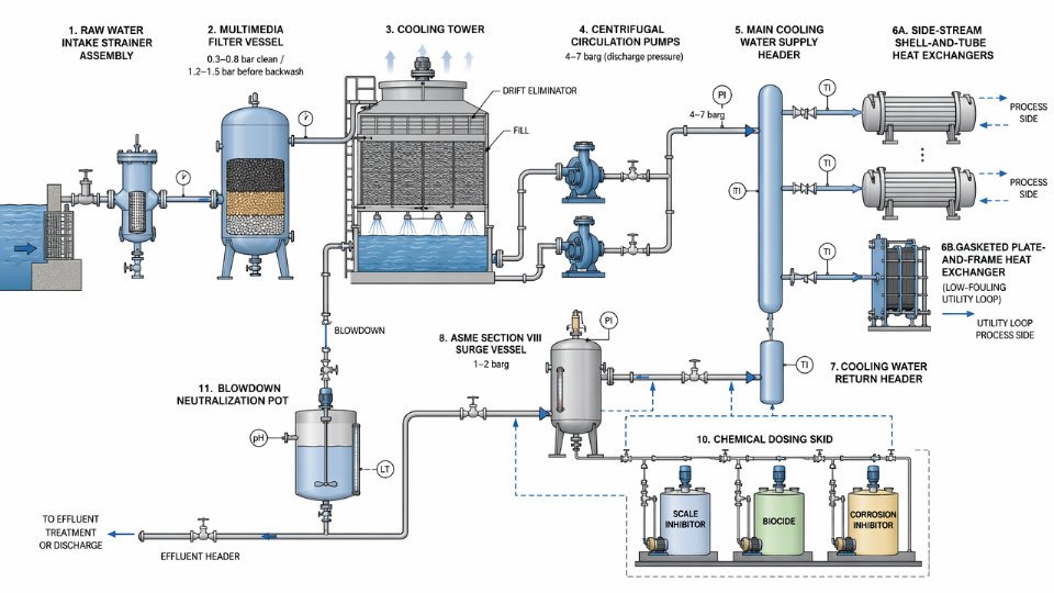
A complete cooling water circuit is longer than most EPC scopes acknowledge. Starting at the makeup water intake: raw water passes through strainer assemblies and multimedia filters (pressure drop typically 0.3–0.8 bar across a clean bed, rising to 1.2–1.5 bar before backwash trigger — the exact threshold depends on influent turbidity and filter media depth). Filtered water feeds the cooling tower basin, where the tower fill, drift eliminators, and structure are usually packaged by one supplier.
The problem starts immediately downstream. Basin outlet piping connects to circulation pumps, which feed the main cooling water header at pressures commonly between 4 and 7 barg at pump discharge for mid-scale complexes. Side-stream heat exchangers — predominantly shell-and-tube in refinery service, sometimes gasketed plate-and-frame for lower-fouling utility loops — pull off this header to handle specific process duty. Chemical dosing vessels, typically small ASME Section VIII vessels between 200 and 2,000 liters, inject scale inhibitor, biocide, and corrosion inhibitor into the supply header or the basin. Surge tanks or expansion vessels absorb hydraulic transients when large process exchangers trip offline suddenly. Finally, blowdown from the tower basin passes through neutralization pots before discharge to the effluent treatment header.
Each of these items carries its own datasheet, its own vendor, and — if procurement does not intervene — its own inconsistent design pressure basis.
Tube Material Selection: Where CAPEX Assumptions Fail in Service
Shell-and-tube exchangers in cooling water service fail faster than process designers expect when water chemistry is treated as someone else’s problem. Carbon steel tubes are acceptable when chloride content stays below roughly 50–100 ppm and biological control is consistent, but operating plants routinely see chloride excursions during seasonal turnover or makeup water source changes. Admiralty brass offers improved resistance up to approximately 200 ppm chloride but is vulnerable to ammonia — a real risk if the facility processes nitrogen-bearing feedstocks and stripping steam leaks into the cooling water loop. Titanium Grade 2 effectively eliminates both concerns and extends tube life from a typical 8–12 year carbon steel interval to 25 years or more, but the installed cost premium runs 3–5× on material alone, which makes it hardest to justify at appropriations stage and easiest to regret five years into operation. Duplex stainless (2205 or 2507) sits in a practical middle ground for high-chloride coastal sites — better pitting resistance than admiralty brass at moderate cost premium — but requires careful weld procedure qualification and post-weld heat treatment review before the mill certification means anything useful.
Surge Vessel Sizing and Pressure Rating Discipline
When a large process exchanger trips offline, its cooling water inventory does not vanish — it hammer-loads the return header. Surge vessel volume is sized against the total fluid inventory in the longest single cooling water sub-loop, the closure speed of the largest isolation valve on that loop, and the acceptable pressure spike at the pump casing. Get those three inputs from three different engineers without reconciling them, and the vessel either throttles the transient inadequately or is oversized by a factor of two.
The ASME Section VIII implication matters here. If cooling water supply headers operate above 10 barg — common in tall structures or long-distance distribution headers where static head and friction loss accumulate — the surge vessels must be rated and stamped accordingly. Procurement teams occasionally specify these as atmospheric or low-pressure vessels to reduce cost, then discover during piping stress analysis that the design pressure basis is non-compliant. Retrofitting an ASME U-stamp on a vessel already delivered to site is not a paperwork exercise; it typically means return to shop, re-inspection of all welds, and re-hydrotesting.
Cooling water surge vessels connected to headers above 10 barg must meet ASME Section VIII Division 1 design pressure requirements, not atmospheric vessel standards.True
ASME Section VIII Division 1 scope begins at 15 psig (approximately 1 barg) internal pressure, but vessel design pressure must envelope the maximum credible operating pressure including hydraulic transients. A header nominally at 8 barg with transient spikes reaching 12 barg requires the vessel to be rated for the higher value. Specifying an atmospheric vessel in this service is a code non-compliance and a mechanical integrity risk.
The Multi-Vendor Split: A Procurement Warning
The most persistent procurement error in cooling water systems is purchasing the cooling tower fill and structure from a tower package vendor, sourcing the basin as a civil-structural item, and then buying circulation pumps and interconnecting exchangers through separate mechanical packages — with no single party responsible for the integrated hydraulic design.
When hydraulic resistance through the fill media is calculated by the tower vendor using assumed pipe losses, and the pump vendor selects impeller trim against a different system curve, and the exchanger vendor rates tube-side pressure drop independently, the composite system curve at commissioning bears little resemblance to any individual vendor’s model. Measured flow through process exchangers may run 15–25% below design, degrading heat transfer duty and forcing process unit turndown before any relief valve or control valve has been blamed. Reconciling this after piping is welded costs multiples of what a single integrated hydraulic study would have cost at the procurement stage.
Flare and Blowdown Systems: Knockout Drums, Seal Drums, and Quench Vessels Procurement Guide
Flare system auxiliary vessels sit at an uncomfortable intersection in EPC procurement: they carry safety-critical pressure vessel classification, they appear on every P&ID review, and they still get treated as near-commodity line items when the purchasing team is under schedule pressure. That combination produces late-stage HAZOP findings, field rework, and — in the worst case — relief system inadequacy that survives all the way to commissioning.
Knockout Drum Sizing: Where API 521 Gets Ignored in Practice
API 521 gives clear methodology for knockout drum sizing, but the two parameters that consistently get shortcut are liquid dropout velocity and residence time. Dropout velocity sets the drum diameter: the actual vapor velocity through the drum must stay below the terminal settling velocity of the largest liquid droplet you need to remove. A typical design target is droplet separation for particles in the 300–600 µm range, though the exact cutoff depends on your flare load case and the fluid system. Get the vapor velocity wrong — usually by undersizing diameter to save steel — and liquid carryover reaches the flare tip. You get smoking, unstable flame, and potential liquid rain-out near grade.
Residence time governs liquid holdup volume. For a large complex with intermittent blowdown from multiple units, residence time of 10–20 minutes is a common target, but the real number is a function of your maximum credible coincident blowdown scenario and the pump-out rate downstream. Undersized holdup is the single most frequent finding when a HAZOP team actually calculates the liquid accumulation rate during a unit emergency shutdown. It is not a theoretical concern. Knockout drums in offsite blowdown headers are routinely found undersized when a complex expands production without revisiting the original flare load study.
Liquid Seal Drum Design: Submergence Depth and Material Selection
The liquid seal drum controls backflow of air into the flare header — a function that sounds simple until you work through the pressure balance. Submergence depth must be calculated against the maximum credible back-pressure on the flare tip side, with a design margin that accounts for liquid density variation as the seal fluid composition changes. A seal using water in refinery service typically targets submergence depths of 200–450 mm, but light hydrocarbon contamination of the seal liquid reduces effective density and erodes your safety margin. If your complex processes sour gas, the seal drum shell and internals need wet H₂S service materials assessment — typically NACE MR0175/ISO 15156-compliant carbon steel with hardness controls, or a duplex grade depending on H₂S partial pressure and temperature.
Pressure drop across the seal drum matters for flare header hydraulics. Designers sometimes treat the seal drum as a zero-resistance element in the header pressure drop calculation. It is not.
Liquid seal drum submergence depth can be calculated using a fixed industry-standard formula independent of process conditions.False
Submergence depth calculation is site-specific: it depends on maximum flare tip back-pressure, seal liquid density (which varies with temperature and contamination), and the required margin against air ingress. API 521 provides methodology but not a universal fixed value.
Quench Vessels and Steam Condensation Hammer
High-pressure blowdown systems that route hot vapor into a quench vessel introduce a real risk of steam condensation-induced water hammer. When hot gas meets subcooled quench water, local condensation can collapse rapidly, generating pressure spikes that ASME vessel design codes do not automatically cover unless the engineer explicitly specifies a dynamic load case. The fix is proper inlet sparger design — distributing the incoming gas flow to limit localized condensation — combined with nozzle reinforcement at the inlet connection. This detail is frequently omitted from vendor data sheets because the buyer’s inquiry did not ask for it.
Water seal vessels integrated into high-pressure blowdown circuits face similar challenges: the water inventory must be maintained within a narrow level band, and the level instrumentation becomes a safety-critical item that needs its own inspection and testing protocol.
Documentation, Certification, and Schedule Reality
These vessels require ASME Section VIII Division 1 U-stamp as a baseline for most international projects; European projects add PED Category III or IV depending on fluid group and volume-pressure product. The schedule consequence of selecting a fabricator without pre-existing U-stamp or PED authorization is not trivial. Witness audits, documentation reviews, and the Notified Body or Authorized Inspector qualification process can add 8–16 weeks to fabrication lead time if the shop has never held the certification. Ask for current certification status and the name of the AI firm before issuing a purchase order — not after award.
Third-party inspection hold and witness points for these vessels should include at minimum: material certification review, NDE on all pressure-retaining welds (RT or TOFD depending on thickness), PWHT verification, and hydrostatic test witness. For sour service, hardness testing at weld HAZ is non-negotiable.
The Scope Gap: Knockout Drum to Liquid Recovery Pump
One interface that regularly falls into a gray zone between EPC package owners is the connection between the flare knockout drum and the liquid recovery pump system. The drum nozzle rating, the minimum flow requirement to keep the pump primed, the high-level shutdown interlock, and the pump discharge routing back to the process — these elements span at least two package scopes. When the flare system package owner and the utility pump package owner each assume the other has defined the interface, the result is undefined nozzle loads, missing instrumentation, and a commissioning punch list that delays first fire of the flare system. Assign this interface explicitly in the project’s scope split matrix, and make sure one discipline lead owns the interlock logic end-to-end.
Utility Steam, Condensate, and Boiler Feed Water Auxiliary Equipment in Complex Offsites
Steam and condensate auxiliary vessels sit at the intersection of every major process unit in an integrated complex. The fired boilers or WHRUs get specified carefully. The turbines get specified carefully. The deaerator, the condensate flash drums, the hotwell — these get a line item in a vessel list and a generic datasheet, often lifted from a previous project with different operating conditions. That gap between attention and consequence is where field modifications, boiler tube failures, and oxygen pitting originate.
The Auxiliary Vessel Inventory Engineers Routinely Undercount
A medium-scale utility steam system serving a 100,000–200,000 BPD equivalent complex will typically include: condensate flash drums (high-pressure and low-pressure stages), a deaerator vessel with its storage section and hotwell, chemical injection pots for oxygen scavenger and amine dosing, sample coolers on BFW and steam condensate streams, and blowdown flash tanks associated with the boiler blowdown circuit. Count them out in a FEED package and you may find eight to fourteen vessels. In early project phases these rarely appear as individual line items — they get bundled under “utility system” with a lump allowance, which means nobody owns the datasheets until detailed engineering is well underway.
Deaerator Operating Envelope and the Nozzle Load Problem
Deaerators in refinery-petrochemical service typically operate in the 0.1–0.3 MPag range for atmospheric/low-pressure tray types, and up to 0.7 MPag for pressurized spray-tray designs. Shell temperatures sit between 105°C and 170°C depending on operating pressure and the inlet steam source. Neither of those figures is aggressive by pressure vessel standards, which is exactly why stress engineers treat the deaerator as a low-priority item in their pipe stress models.
The consequence plays out at the feed nozzles. Condensate return lines from multiple process units converge at the deaerator with significant thermal expansion, and the actual nozzle loads — moments and forces combined — frequently exceed the allowable values the vessel fabricator assumed when sizing the nozzle reinforcement and setting the support configuration. When this surfaces during stress analysis sign-off, the fix is either a costly field modification to the piping layout or a vessel nozzle rerate that requires the fabricator’s involvement and possibly a code stamp revision. Specify allowable nozzle loads explicitly on the vessel datasheet, referenced to WRC-107/WRC-297 or the equivalent FEA basis, before the purchase order is issued.
Condensate Flash Drum Sizing: Vapor Fraction and Header Connection
Condensate returning from high-pressure steam users carries significant sensible heat. When it flashes to a lower pressure — typically the LP steam header pressure, which ranges from 0.3 MPag to 0.7 MPag across different complexes — the vapor fraction can run 8–18% by weight depending on the upstream condensate pressure and the flash pressure differential. Undersizing the flash drum vapor space produces liquid carryover into the LP steam header, which means wet steam reaching users downstream and, in worst cases, water hammer in steam tracing or reboiler circuits.
Size the flash drum with a conservative vapor disengagement velocity — typically 0.05–0.15 m/s superficial vapor velocity at drum cross-section — and confirm the vapor recovery line connection is sized for two-phase slugging at turndown conditions, not just steady-state design flow.
BFW Preheat Exchanger Fouling and Specification Language
Boiler feed water preheat exchangers are chronically fouled in complexes where condensate quality is variable. When process unit upsets push hydrocarbon or chemical contamination into the condensate return system, that contamination concentrates on BFW exchanger surfaces. Fouling factors of 0.0002–0.0004 m²·K/W are commonly assumed in design; actual measured values under poor condensate quality conditions can run two to three times higher.
The specification needs to address cleanability directly: specify removable bundles with a minimum cleaning lane clearance of 600–750 mm on the shell side, state the maximum allowable tube-side velocity to limit erosion during high-velocity cleaning, and require the vendor to document bundle removal procedure as a deliverable. If the complex has a history of condensate contamination events — and most do — consider specifying duplex stainless or titanium tubes rather than admiralty brass, accepting the higher initial cost against the maintenance cycle reduction.
Deaerators in refinery-petrochemical complexes are low-risk vessels that require minimal nozzle load specificationFalse
Converging condensate return lines from multiple process units create significant combined thermal expansion loads at deaerator nozzles. If allowable nozzle loads are not explicitly specified on the vessel datasheet before fabrication, the result is frequently field piping modifications or nozzle rerework after stress analysis sign-off — both costly and schedule-impacting.
Effluent Treatment and Produced Water Separation Equipment: Vessel Selection for Environmental Compliance
Effluent treatment sits at the downstream end of every refinery complex, which is precisely why it collects scope gaps like a drain collects oil. By the time detailed engineering reaches the wastewater circuit, budget contingency is thin, schedule pressure is real, and the separation equipment train has often been parceled across the civil, process, and environmental packages with no single owner. That fragmentation is where costly omissions breed.
The Separation Equipment Train and What Each Stage Actually Does
A conventional refinery effluent system runs sequentially: gravity API separator, corrugated plate interceptor (CPI), dissolved air flotation (DAF) unit, and equalization tank, with polishing steps added for sensitive discharge points. Each stage has a defined job. The API separator removes free oil and settleable solids by gravity; residence times typically range from 20 to 30 minutes, depending on inlet oil load and temperature. The CPI downstream handles dispersed oil droplets in the 20–150 µm range — coalescing plates reduce the effective rise distance and allow a much smaller footprint than a second gravity settler. The DAF handles emulsified and colloidal fractions that neither gravity nor coalescing plates can remove economically.
Where EPC buyers consistently undersize is the equalization tank. Refinery effluent flows are not steady. Batch draining events, unit upsets, and steam condensate slugs create flow surges that, without adequate equalization volume, push hydraulic loads far beyond what the biological or advanced treatment downstream can absorb. A rule of thumb that holds up in practice: equalization volume of 4–8 hours of average daily flow, with the actual figure driven by the number of independent drain headers feeding the system and the likelihood of simultaneous upsets.
Discharge Limits as Design Parameters, Not Afterthoughts
Regional regulations for oil-in-water discharge commonly sit in the 10–15 mg/L range for coastal or inland surface water discharge — though specific limits vary significantly by jurisdiction, permit conditions, and whether the receiving water body has special sensitivity. That number has to work backward into CPI and DAF vessel sizing. A CPI designed to achieve 30 mg/L effluent quality is not a CPI designed to achieve 10 mg/L; the plate spacing, pack length, and inlet distribution geometry are different. EPC buyers who accept a vendor’s standard CPI module without specifying the guaranteed outlet oil-in-water concentration at a defined inlet load are accepting performance risk they may not discover until the environmental commissioning test.
A CPI unit sized to API 421 guidelines and achieving 30 mg/L outlet quality can be repackaged with a shorter plate pack and presented as meeting 10 mg/L discharge limits without any design change.False
Achieving 10 mg/L oil-in-water from a CPI requires longer plate packs, tighter plate spacing, and often inlet flow conditioning — standard API 421 sizing for 30 mg/L will not achieve this without redesign. Vendors who claim otherwise should be asked to provide validated pilot data or third-party performance records at the specified inlet loading.
Materials of Construction: H₂S and High-TDS Service
Produced water from hydroprocessing or sour crude units can carry H₂S concentrations sufficient to cause blistering in carbon steel without adequate protection, and TDS levels above 50,000 mg/L are not unusual in some crude slates. That combination creates a fabrication decision with real schedule consequences.
Rubber lining on carbon steel is the most cost-effective option for large-diameter equalization tanks and API separator chambers where temperatures stay below roughly 60–70°C; expect 8–14 weeks of additional shop time for lining and curing on top of vessel fabrication. FRP construction eliminates corrosion risk entirely but introduces structural limitations — large-span covers and internal equipment attachments require careful engineering review, and FRP vessels above about 4 meters diameter require vendors with genuine heavy FRP fabrication experience, not just tank lining shops. Duplex stainless (2205 or 2507) handles both H₂S and chloride stress cracking and allows full mechanical attachment flexibility, but material lead times of 16–28 weeks from mill order are realistic depending on product form and rolling schedule. That lead time, if not captured in the procurement schedule at FEED exit, can sit on the critical path unnoticed until detailed engineering is 60% complete.
Performance Testing: Writing FAT and SAT Protocols That Actually Protect the EPC Contractor
Factory acceptance testing for oil-water separation equipment is frequently inadequate — a dimensional check, a hydrostatic test, and a visual inspection of internals. That does not test the one thing that matters: separation performance. A well-written FAT protocol for a CPI or DAF unit should require the vendor to demonstrate plate pack integrity, inlet distributor uniformity across the full flow range, and sludge removal mechanism function. Where pilot plant data exists for the specific effluent chemistry, the FAT should verify that the design basis matches it.
SAT protocols need to specify the acceptance criterion clearly: oil-in-water measured at the vessel outlet, at a defined feed loading, using a defined analytical method (typically EPA Method 1664 or equivalent), over a minimum continuous operating period — 72 hours is a reasonable minimum. Without that specificity, a vendor can claim compliance on a single grab sample taken during favorable operating conditions.
The Oily Sludge and Slop Oil Interface: A Scope Gap That Recurs
The slop oil recovery vessel and oily sludge collection system are almost always defined in a different package than the effluent treatment vessels — sometimes in the tank farm scope, sometimes in the utility scope, occasionally in neither. During detailed engineering, the interface question surfaces: where does the API separator sludge go, who owns the slop oil return line back to the crude unit, and is there a dedicated vessel for slop oil blending and settling before reprocessing? These items are small individually — a 20–80 m³ vessel in most cases — but their absence causes mechanical completion punch lists and, more seriously, creates undefined discharge paths during initial operation that put environmental permit compliance at risk before the complex has run a single barrel.
Interconnecting Separation Equipment: Slop Drums, Interface Vessels, and Pig Receivers Outside Battery Limits
These vessels sit in the gaps — physically between process units, tankage farms, and export pipelines, and organizationally between EPC package scopes. Slop oil recovery drums, pipeline pig receivers and launchers, product interface detection vessels, and pressure surge dampers outside individual unit battery limits rarely appear as starred line items in FEED-stage equipment lists. They get picked up late, assigned to whichever subcontract happens to be closest in scope, and then quietly cause schedule problems when the fabricator’s documentation package doesn’t match project code requirements.
Why This Category Gets Orphaned in EPC Package Structures
The root issue is boundary definition. A slop drum sitting 40 meters from the crude desalter is outside the desalter unit battery limit but feeds directly into crude charge recovery. The pipeline pig receiver at the terminal end of an import line sits outside every process unit boundary limit. Neither item fits cleanly into a process unit equipment package, a tankage package, or a pipeline package. In practice, the item lands in a miscellaneous equipment list that gets issued to procurement late — sometimes after the main vessel packages have already been awarded.
The consequence is predictable: expedited fabrication, compressed documentation review, and field installation that reveals specification gaps nobody caught during the rushed procurement cycle.
Pig Receivers and Launchers: Code Boundary Errors Are Common
This is where the most consequential specification errors occur. A pipeline pig trap is a pressure vessel by geometry and function, but it connects directly to a pipeline operating under ASME B31.4 (liquid petroleum) or B31.3 (process piping). The barrel section and closure — the pressure-retaining envelope — must be designed and stamped to ASME Section VIII, Division 1 if it exceeds the thresholds that remove it from piping code scope. The connected pipeline remains under B31.4 or B31.3. Many procurement teams write a single specification that references the pipeline code throughout, which means the vessel fabricator may never involve a third-party ASME-authorized inspection agency. The result is a vessel that arrives on site without an ASME “U” stamp and cannot be legally commissioned.
A pipeline pig trap barrel that forms a pressure vessel under ASME VIII criteria cannot be brought into service using only a B31.4 piping code certification, regardless of operating pressure.True
ASME B31.4 governs the connected piping, but once the barrel geometry and closure create a pressure vessel as defined by ASME VIII scope, the vessel itself requires ASME VIII design, inspection, and stamping. These are separate jurisdictional requirements that run in parallel, not in sequence.
Pig trap closure design deserves separate attention. Quick-opening closures on large-diameter receivers (NPS 16 and above) are subject to OSHA PSM and similar regulatory requirements in many jurisdictions when the contained fluid is flammable. Some project specifications omit the quick-opening closure safety interlock requirements entirely, leaving the detail to the pipeline equipment specialist — who may subcontract the pressure vessel barrel to a shop that has never seen the project’s inspection and testing plan.
Slop Drum Sizing: Hold-Up Time and Interface Control Philosophy
Slop drums are gravity separation vessels, and their sizing logic follows from two independent requirements: adequate hold-up volume for the worst-case flow rate entering the drum, and sufficient residence time for free water to drop out of oil before the oil phase is returned to the crude charge system or routed to off-spec product recovery.
Hold-up time for the oil phase typically runs 20–45 minutes depending on the density spread between the slop oil and the aqueous phase, the expected emulsion tendency of the specific crude slate, and whether the drum operates at ambient or slightly elevated temperature. A drum sized only for average flow rates will fill and overflow during a unit upset — exactly when slop generation peaks.
Interface level control philosophy is the second design decision that gets underspecified. A fixed weir without interface-level detection will pass contaminated water into the oil return line during upsets. Vendors offering a simple level controller on oil outlet without a separate aqueous-phase interface detector are providing an undersized control philosophy for anything other than clean, low-emulsion service. Projects handling waxy crudes or crudes with high asphaltene content typically need a combination of guided-wave radar and a dedicated water draw-off with its own level loop — and the nozzle layout must support that from the outset.
Vendor Coordination: The Sub-Supplier Code Stamp Gap
Pipeline pig trap packages are typically supplied by specialists in pipeline inline inspection and pigging systems. Their core competency is the mechanical handling equipment — the closure mechanism, guide rails, signaler, drain and vent connections, and the kicker-line arrangement. The pressure vessel barrel is often subcontracted to a structural or pressure vessel shop. That sub-supplier may hold ASME certification for standard pressure vessels but may not hold the specific material certifications, NDE qualifications, or PWHT capabilities required by the project specification — particularly when the project requires sour service compliance per NACE MR0175/ISO 15156.
The practical mitigation is straightforward: require the pig trap vendor to submit their intended sub-supplier’s ASME Certificate of Authorization, their authorized inspection agency’s current accreditation, and a preliminary inspection and test plan before purchase order award — not at the pre-inspection meeting after fabrication has started. Procurement teams that treat this as a routine pipeline equipment purchase and skip the vessel-specific document requirements routinely discover the problem at the final inspection stage, when schedule recovery options are expensive and limited.
Procurement Strategy: Bundling vs. Splitting Offsite Equipment Packages for Schedule and Cost Control
The instinct on most EPC projects is to break offsite equipment into the smallest possible line items, assign each to the lowest-cost qualified bidder, and let the procurement team manage the matrix. That approach looks efficient on a spreadsheet. On the plant floor, it routinely produces interface disputes, inspection bottlenecks, and last-minute field modifications that cost more than any unit-price savings achieved at award.
The Case for Bundling Functionally Related Vessel Groups
When a flare system includes a knockout drum, a seal drum, and a quench vessel, those three items share a pressure envelope, a common process fluid basis, and — critically — a single safety function. Splitting them across three fabricators means three separate material traceability chains, three inspection schedules to coordinate, and three sets of nozzle orientation drawings to reconcile with the flare header vendor. A single fabrication error on a flange face height at one vessel can hold up mechanical completion on all three, because they assemble in sequence.
Bundling the complete flare drum set to one qualified pressure vessel fabricator consolidates that accountability. The shop handles all PMI records, heat number tracking, and NDE documentation under one data book. The third-party inspection agency schedules one mobilization per witness point rather than three. For cooling water auxiliary equipment — surge vessels, chemical dosing skid vessels, blowdown receivers — the same logic applies. These items share carbon steel material specifications, standard ASME VIII Div.1 design, and similar hydrostatic test pressures. A competent general fabricator can run them as a batch, reducing setup costs and keeping weld procedure qualifications consistent across the package.
When Splitting Packages Is the Right Call
Large-diameter atmospheric storage tanks are the clearest exception. A 50,000 m³ floating-roof crude tank built to API 650 requires specialist plate rolling, annular plate welding, and pontoon fabrication — capabilities that a shop running process vessels at 1,500 mm diameter simply does not have. Forcing that tank into a bundled offsite package dominated by small utility vessels either inflates the small vessel cost (because the tank specialist prices the utility work at a premium) or exposes the tank to a fabricator whose field erection crew has no relevant large-tank experience. Keep the large-diameter atmospheric tanks as standalone packages awarded to fabricators with demonstrable API 650 shop or field erection history.
Small utility vessels below roughly 2 m diameter and 10 bar design pressure — flash vessels, condensate collection drums, sample cooler shells — can go to general fabricators, but only if those fabricators hold the relevant code stamp and can demonstrate in-house PWHT capability for any alloy grades specified. Sending a P91 or 304L stainless vessel to a shop that subcontracts PWHT adds two to four weeks of logistics per vessel and introduces a quality custody gap that the EPC inspector cannot easily audit.
Aligning Requisitions With the FEED-to-EPC Transition
Large atmospheric storage tanks (API 650, greater than 10,000 m³) typically require 28–52 weeks from purchase order to mechanical completionTrue
This range reflects actual fabrication and field erection cycles reported across multiple refinery and terminal projects; the spread depends on tank diameter, roof type, steel plate sourcing lead time, and whether erection is shop-built or field-erected.
That range means requisitions for large tanks must leave the procurement desk no later than the FEED gate closure — before detailed engineering is complete. Waiting for issued-for-construction drawings to finalize before floating an RFQ adds four to eight weeks that the schedule simply does not have. Issue performance specifications and preliminary datasheets at FEED exit; follow with certified drawings as an addendum after award.
For mid-tier offsite vessels — deaerators, slop drums, pig receiver barrels — fabrication typically runs 16–28 weeks depending on nozzle complexity, internals, and coating requirements. These can wait for the early detailed engineering phase, but requisitions should be raised within six to eight weeks of EPC contract award, not held until the full equipment list is frozen.
Vendor Pre-Qualification Criteria That Offsite Equipment Actually Demands
Pre-qualification questionnaires for offsite vessels should go beyond code stamp verification. Ask specifically whether the shop’s radiography is in-house or subcontracted — a fabricator who sends film to an external RT crew adds unpredictable cycle time and loses direct control over retake decisions. Confirm hydrostatic test bay capacity: a shop that can fabricate a 3 m diameter, 12 m long vessel but can only hydrotest up to 2 m diameter has a serious throughput bottleneck that will not become visible until the vessel is complete and sitting on the shop floor waiting for a test bay opening.
For export projects, verify export crating and sea-fastening experience directly. A technically excellent fabricator who has never shipped overseas will underestimate crating weights, miss fumigation certificate requirements, and produce shipping marks that do not comply with the destination port’s documentation standards. That last point sounds administrative. It has held equipment at customs for three to six weeks on real projects.
Inspection, Testing, and Documentation Requirements That Protect EPC Buyers at Handover
Offsite equipment routinely enters the value engineering crosshairs late in the EPC cycle, and the first items cut are usually inspection hold points and documentation scope. The reasoning sounds plausible at the time — these are “simple” vessels, the schedule is tight, the vendor is reputable. Then mechanical completion arrives and the project team discovers a deaerator with an unwitnessed hydrostatic test, a slop drum whose nozzle orientations don’t match the issued P&ID, and a manufacturer data record that’s missing half the required weld maps. Fixing those problems in the field, under commissioning pressure, costs multiples of what a proper inspection program would have cost during fabrication.
Minimum Hold Points for Pressure Vessels in Offsite Service
A defensible inspection plan for offsite pressure vessels covers six discrete gates, and none of them are optional in practice even when the contract language leaves them as “review” rather than “witness.”
Material receiving inspection verifies mill certificates against the purchase order specification before any cutting or forming begins. Heat and lot traceability matters here — carbon steel plate for a blowdown drum and low-temperature carbon steel for a winterized flash vessel look identical on the shop floor and get mixed up more often than vendors admit.
Fit-up and dimensional check happens after shell rolling and before any weld seam is closed. Nozzle orientation, shell out-of-roundness, and major assembly dimensions are far cheaper to correct at this stage than after full welding. For tall vertical vessels, plumb tolerance and base plate bolt-circle accuracy need to be confirmed against foundation drawings — a 10,000-litre condensate collection drum with a mislocated anchor bolt circle requires concrete demolition in the field.
Weld visual and NDE hold points should be sequenced to the welding progress, not deferred to a single end-of-fabrication sweep. RT or UT on completed joints before they become inaccessible behind insulation support rings is basic shop practice that some vendors skip when no inspector is present.
PWHT witness applies whenever the material specification or wall thickness triggers post-weld heat treatment under ASME VIII Div. 1 or the applicable code. Time-temperature charts must be reviewed against the qualified procedure, not just filed. Thermocouples placed too far from the weld heat-affected zone produce a passing chart that tells you nothing useful.
Hydrostatic test witness — with the test medium temperature, hold duration, and pressure verified against the stamped data report — is the one hold point most owners protect. But pneumatic testing for vessels that cannot tolerate residual water (certain low-temperature service drums, for example) requires a separate risk assessment and enhanced NDE beforehand; accepting pneumatic test without confirming that enhanced NDE has been completed is a liability that will surface in any future incident investigation.
Final dimensional and nozzle orientation verification, with a signed red-line confirmation against the approved general arrangement drawing, closes the fabrication record. This step is skipped surprisingly often on rush deliveries.
The MDR/MRB Package: What Must Be in It
The manufacturer’s data record (MDR), or manufacturer’s record book (MRB) depending on the project convention, is the legal and technical passport for the vessel’s entire operating life. For ASME U-stamp vessels, the package must include the completed Form U-1 data report, all supporting weld procedure specifications and procedure qualification records, welder qualification records, full NDE reports with film or digital image archives, PWHT records, hydrostatic test record, and material test reports traceable to each pressure-retaining component. For PED CE-marked equipment destined for European installations, the technical file must satisfy the conformity assessment route applicable to the vessel category — typically Module G (unit verification) or Module H1 for higher-risk equipment — and the notified body’s countersigned documentation must travel with the vessel, not arrive months later.
A common EPC shortcut is accepting a “preliminary” MDR at mechanical completion with the promise of a final version within 30–60 days. That gap regularly stretches to six months or longer once the vendor moves on to the next job, and an incomplete MDR means the vessel technically cannot be legally commissioned in jurisdictions where the operating permit requires a complete conformity record.
Partial NDE on Cyclic and Low-Temperature Vessels: A Real Risk
Spot radiography (10% RT) provides equivalent weld quality assurance to 100% RT for pressure vessels in cyclic offsite service.False
Spot radiography is a statistical sampling method that satisfies code minimum requirements for Joint Efficiency Category B under ASME VIII Div. 1, but it does not detect weld defects in the 90% of seam length that is not examined. For vessels subject to thermal cycling — deaerators, flash drums, blowdown knockout drums — undetected planar defects in partially examined seams are fatigue crack initiation sites. For low-temperature service vessels where nil-ductility transition temperature requirements apply, an undetected lack-of-fusion defect can trigger brittle fracture at startup in cold ambient conditions.
The practical consequence: if value engineering has already reduced weld joint efficiency from 1.0 to 0.85 by specifying spot RT instead of full RT, the vessel wall is already thicker than the full-RT version would require. That means more weld metal, more PWHT exposure, and heavier lifting weights — while still carrying more long-term risk. The cost trade-off rarely survives honest scrutiny.
Nameplate and Tagging: The Asset Management Problem Nobody Notices Until Turnaround
Mismatched tag numbers are endemic in offsite equipment. The sequence typically runs like this: the FEED package assigns preliminary tag numbers, detailed engineering revises them, the purchase order is issued with one revision, the vendor stamps the nameplate from an earlier datasheet, and the P&ID reaches its final issue-for-construction state after the nameplate is already welded on. The result is a physical vessel with a tag that matches none of the current-revision documents.
During initial commissioning, operators who know the project work around the discrepancy. Four years later during a turnaround, a contract maintenance crew isolating equipment from a current P&ID cannot positively confirm which physical vessel corresponds to which P&ID tag. Isolation errors in offsite systems — particularly in the flare, blowdown, and effluent treatment circuits — carry real safety and environmental consequences.
The fix is contractually simple: require nameplate data to be confirmed against the final-revision instrument index before mechanical completion sign-off, and make tag number reconciliation a prerequisite for MDR acceptance. The cost is a single inspection step. The alternative is a permanent asset management discrepancy that propagates through every document revision, every RBI assessment, and every future turnaround planning package for the life of the plant.
Frequently Asked Questions About Offsite Equipment in Refinery-Petrochemical EPC Projects
What is the difference between offsite equipment and utility systems in a refinery complex, and how does this affect EPC package boundaries?
The terms get used interchangeably in early project documents, which is exactly where the problem starts. Offsite equipment refers to vessels, tanks, exchangers, and skids located outside process unit battery limits — storage tankage, flare headers, effluent ponds, interconnecting pipelines. Utility systems are the supply infrastructure: steam generation, instrument air, cooling water supply headers, electrical substations. The distinction matters because EPC package structures often follow this boundary, creating orphaned equipment. A cooling water surge drum sitting on the pipe rack between the cooling tower and the process unit header belongs operationally to neither the cooling water package nor the process unit mechanical package. Unless the project’s Work Breakdown Structure explicitly assigns it, nobody owns the ITP, the vendor datasheet review, or the commissioning procedure. Clarify the boundary in the project execution plan before FEED is complete, not during detailed engineering when vendors are already quoting.
Which offsite vessels require ASME Section VIII certification versus those that can be fabricated to local pressure vessel codes in projects outside North America?
This depends on the owner’s specification, the host country’s statutory requirements, and — critically — the financing institution’s conditions. Export credit agencies and multilateral development bank-financed projects routinely mandate ASME VIII Div. 1 or equivalent EN 13445 even when local code would suffice. In practice, vessels above roughly 1.5 MPa design pressure or containing H₂S service almost always carry a mandatory international code requirement regardless of geography. Below that threshold, fabrication to PD 5500, GB 150, or AS 1210 is contractually acceptable on many projects. The procurement risk is assuming local code is acceptable and then receiving a client or lender audit 14 months into fabrication that demands ASME re-stamping — a delay that typically runs 8–16 weeks and costs 15–30% of the original vessel value depending on current Authorized Inspector availability and the shop’s existing ASME U-stamp scope.
Vessels fabricated to local pressure vessel codes can always be re-stamped to ASME VIII after completion with minimal rework.False
Re-stamping requires an Authorized Inspector to verify material traceability, welding procedure records, and radiography from the original fabrication. If documentation was not maintained to ASME requirements from the start, the vessel may need weld repairs, retesting, or in the worst case, rejection. Retroactive compliance is expensive and not always achievable.
How early in the EPC schedule should offsite storage tanks and flare system vessels be requisitioned to avoid commissioning delays?
For atmospheric storage tanks above 10,000 m³ under API 650, requisition at or before the end of FEED — typically 36–48 months before planned mechanical completion. Fabrication and field erection alone consume 28–52 weeks depending on tank diameter, shell course count, floating roof complexity, and yard loading at the fabricator. Flare knockout drums and seal drums in safety-critical service carry long-lead refractory lining and internal device lead times of their own; 20–32 weeks from PO to delivery is realistic for a properly specified vessel. Projects that wait for IFC drawings before issuing RFQs on these items routinely find themselves compressing commissioning sequences or commissioning process units without a functional flare system — a scenario that regulators in most jurisdictions will not permit.
Can cooling water surge vessels and chemical dosing skids be sourced from the same vendor as the cooling tower structure, and what are the risks of doing so?
It is commercially convenient and sometimes schedule-efficient, but carries a specific accountability risk. Cooling tower vendors are structural and thermal specialists. Their pressure vessel engineering capability varies widely. A surge drum that a cooling tower vendor subcontracts to an unfamiliar pressure vessel shop may arrive without the NDE records, material test reports, or nameplate documentation required by the owner’s inspection standard.

Split the scope only if you have verified the cooling tower vendor’s pressure vessel subcontractor quality system independently. If the cooling tower vendor cannot provide an approved pressure vessel subcontractor list with audit history, separate the packages and single-source the surge drum through your standard pressure vessel vendor list.
What performance guarantees are reasonable to demand from vendors supplying oil-water separation equipment for produced water treatment in offsite systems?
Outlet oil-in-water concentration guarantees in the range of 10–30 mg/L are achievable from established gravity separation and coalescing equipment vendors, depending on inlet emulsion stability, temperature, and flow turndown ratio. Demand that the guarantee be stated at minimum flow as well as design flow — separators frequently underperform during unit startup and low-throughput operation when residence time distributions shift. Also require a solids loading tolerance in the guarantee; produced water with suspended solids above 50–100 mg/L will blind coalescing media faster than vendors typically disclose in proposal documents.
How should EPC contractors handle scope gaps for pig receivers and slop drums that fall outside both the pipeline and the process unit package boundaries?
Assign a single responsible engineering discipline — typically the offsite or tankage lead — and document it in the project responsibility matrix before detailed engineering begins. Pig receivers outside battery limits are one of the most commonly orphaned items in EPC execution. They are too small to draw attention, too safety-relevant to leave unspecified, and they sit in a geographical and contractual no-man’s land. A pig receiver that arrives on-site without a properly sized isolation valve arrangement, a drain connection routed to the correct closed-drain header, and a coded pressure vessel certificate will stall pipeline pre-commissioning. The fix always costs more in field labor and schedule impact than the 20–40 engineering hours required to close the scope gap in the office.