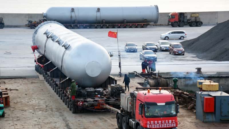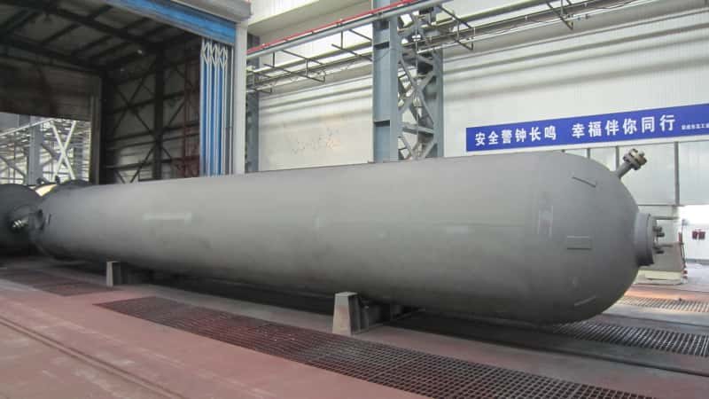

Specify the wrong design pressure on a reactor vessel and you will not discover the mistake during the engineering review — you will discover it during an unplanned shutdown, when a relief valve lifts prematurely, or worse, when a weld seam fails under cyclic thermal loading. Either event stops production. In a continuous-process chemical plant, even a 12-to-48-hour outage on a critical vessel can erase weeks of margin, trigger contract penalties, and set off a cascade of off-spec inventory that has nowhere to go. Getting pressure vessel selection and specification right is not a procurement checkbox; it is a production risk decision.
Pressure vessels in a chemical plant are closed containers engineered to hold fluids or gases at pressures substantially above or below atmospheric — typically 0.1 MPa to 35 MPa for most chemical service, with specialized synthesis reactors exceeding 100 MPa. They perform five core functions across any plant: chemical reaction, phase separation, heat exchange, bulk storage, and process buffering. Every major process unit depends on at least one of them.
What makes this equipment category unusually consequential is how many distinct jobs it performs simultaneously across a single facility. The same design language — a pressure-rated shell, code-compliant nozzles, a defined inspection regime — gets applied to a high-pressure polymerization reactor, a three-phase separator downstream of a distillation column, a jacketed storage tank holding a temperature-sensitive intermediate, and a surge drum smoothing feed fluctuations into a compressor. Each application carries its own failure mode, its own procurement standard, and its own cost driver. Understanding where each vessel type sits in the process — and why it is specified the way it is — is the starting point for anyone buying, building, or approving this equipment.
Reaction Vessels: Where Chemistry Happens Under Controlled Pressure
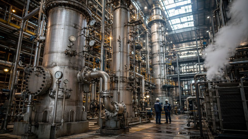
Pressure rises inside a reactor for a reason. Elevated pressure compresses gas-phase reactants, shifting equilibrium toward products in reactions that reduce molar volume — the Le Chatelier principle put to industrial work. It also forces gases into solution, increasing effective reagent concentration at the catalyst surface and cutting residence time. These two effects explain why so many chemical reactions that look straightforward at atmospheric conditions only become economically viable once you add pressure.
Process Conditions That Define the Category
Ammonia synthesis runs at 150–300 bar and 400–500 °C, depending on catalyst age and loop configuration. Those numbers aren’t arbitrary — they represent the operating window where nitrogen conversion per pass is commercially acceptable without destroying the iron catalyst through sintering. Hydrocracking operates at 70–200 bar hydrogen partial pressure, the range varying with feedstock heaviness and target product slate. At the low end you’re processing light vacuum gas oil; at the high end, residue hydrocracking demands vessels that most fabricators won’t quote without a detailed pre-bid review.
Polymerization reactors occupy a different corner of the same category. High-density polyethylene autoclave reactors, for instance, can operate at 1,000–3,000 bar in tubular configurations — pressure levels that push most standard fabrication codes to their limits and require forged construction rather than welded plate. Catalytic fixed-bed reactors for reforming or hydrotreating sit at a comparatively modest 30–80 bar, but cyclic regeneration cycles introduce thermal fatigue that accumulates over years.
What Buyers Actually Specify
When a procurement team writes a reaction vessel requisition, the design pressure and temperature are just the starting point. Experienced buyers layer on:
Corrosion allowance. A hydrogenation vessel handling hydrogen sulfide in a sour service environment might carry 3–6 mm corrosion allowance on top of calculated thickness, depending on expected service life and inspection interval. Skimping here is a deferred cost, not a saving.
Lining and cladding selection. Base carbon steel or low-alloy steel carries the mechanical load; the lining handles the chemistry. 316L stainless steel is adequate for mild organic acid environments. Hastelloy C-276 gets specified for mixed acid service or halide-containing streams where 316L pits within a single campaign. Titanium cladding appears in reactors handling hot concentrated nitric acid or wet chlorine. Each material step up roughly doubles the wetted-surface material cost, sometimes more for titanium or high-nickel alloys, so selection has to be grounded in actual corrosion data rather than conservative habit.
Agitator and nozzle layout. Batch reactors for fine chemicals or pharmaceuticals almost always include an agitator, and the nozzle-to-agitator geometry affects mixing efficiency in ways that matter to yield. Procurement managers who specify nozzle positions without consulting process engineering first create problems on site that fabricators can’t fix after the vessel ships.
Jacket configuration. Heat management in exothermic reactions is not optional. Half-pipe jackets handle higher jacket-side pressure and give better thermal cycling resistance than conventional plate jackets. Dimple jackets are cheaper for lower-pressure utility service. Getting this wrong means inadequate heat removal during runaway-prone reactions — a process safety failure, not just an efficiency issue.
Fatigue, Fracture Toughness, and Code Route Selection
Cyclic pressure-temperature profiles accumulate fatigue damage. A reactor that pressurizes and depressurizes once per batch, running 200 batches per year over a 20-year design life, accumulates 4,000 cycles — enough to require explicit fatigue analysis under ASME Section VIII Division 2 or EN 13445 Annex C rather than the simplified rules in Division 1.
ASME Section VIII Division 2 requires a formal fatigue analysis when cyclic service is anticipated, while Division 1 relies on general design margins without explicit cycle-by-cycle assessment.True
Division 2 Part 5 mandates fatigue evaluation under design-by-analysis rules; Division 1 uses pressure-based safety factors that do not account for cyclic loading explicitly, making it unsuitable as the sole design basis for vessels with significant pressure cycling.
Division 2 is not inherently more conservative everywhere — it actually permits lower wall thickness through more rigorous stress analysis, which can reduce material cost on thick-wall vessels. The tradeoff is higher engineering cost and longer vendor qualification time, typically 4–10 weeks longer on the procurement schedule. For a reactor above 50 mm wall thickness, that engineering investment usually pays back in material savings. Below that threshold, most buyers stay on Division 1 unless the cyclic count or fracture toughness requirements force the issue.
Catalyst loading access also drives mechanical design. Fixed-bed reactors need large manways — typically 600 mm minimum clear opening — positioned and reinforced so repeated catalyst changeout doesn’t induce local stress concentrations over time. Buyers who copy-paste nozzle schedules from a previous project without checking opening reinforcement calculations create vessels that crack around manway necks within a few regeneration cycles.
Separation Vessels: Distillation Columns, Absorbers, Flash Drums, and Scrubbers
Separation duty covers the widest variety of pressure vessel geometries in any chemical plant, and it’s where misspecification causes the most expensive rework. A fabricator quoting a flash drum and a fabricator quoting a structured-packing absorber are solving fundamentally different engineering problems — even though both vessels may sit within a hundred meters of each other on the plot plan.
Flash Drums and Knockout Drums
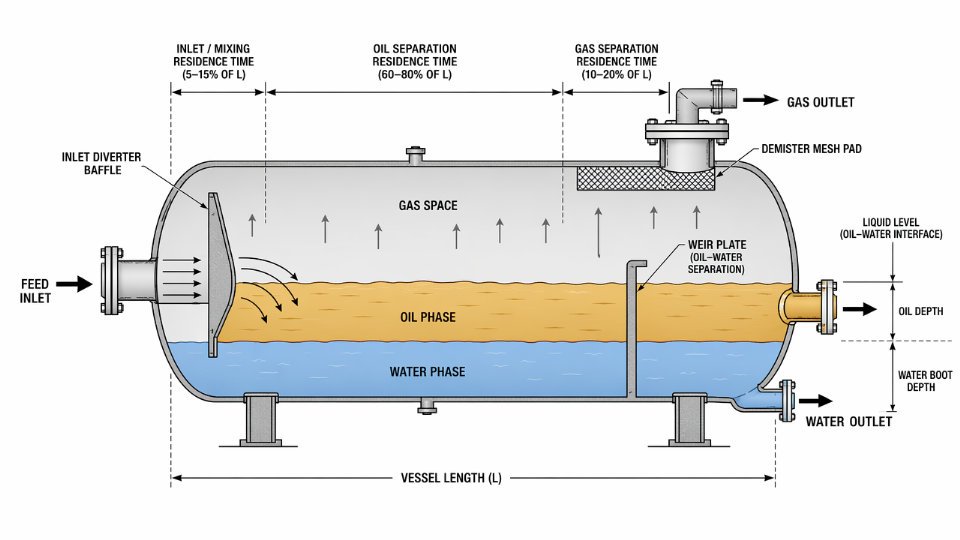
A flash drum exploits the sudden pressure drop across a control valve to partition a feed stream into a vapor phase and a liquid phase. The vessel itself is not doing chemistry; it’s providing residence time — typically 3 to 5 minutes for the liquid — so entrained droplets settle before vapor exits the top nozzle. Diameter is set by the maximum allowable vapor velocity, which is calculated from the Souders-Brown coefficient and depends on operating pressure, fluid densities, and whether a mist eliminator mesh pad or vane pack is installed. Get the vapor velocity wrong and liquid carryover contaminates downstream compressors or heat exchangers.
Knockout drums ahead of compressor suction are a specific, high-consequence application. Liquid slugs entering a reciprocating compressor can fracture valves or, worse, cause a hydraulic lock event that damages the cylinder. The required separation efficiency in this service is non-negotiable, which is why procurement specifications for compressor suction scrubbers almost always call out a specific demister style and a drain loop design rather than leaving internals to the fabricator’s discretion.
Three-phase separators — handling gas, a hydrocarbon liquid, and a water phase simultaneously — add a horizontal boot or a weir arrangement to the design. Residence time requirements for each liquid phase must be specified independently. Feed water cut, emulsion tendency, and any presence of surfactants all affect whether a simple weir suffices or whether a coalescer pack is needed to meet the required water-in-oil or oil-in-water spec at the outlets.
Absorption Columns and Gas Sweetening Service
Absorption columns bring a gas stream into countercurrent contact with a liquid solvent to remove a target component — H₂S and CO₂ in amine gas sweetening, SO₂ in flue-gas scrubbing, HCl vapor in chlorine plant tail-gas treatment. The pressure range varies enormously: atmospheric scrubbers in environmental compliance service operate at essentially ambient conditions, while high-pressure amine absorbers in natural gas processing run at 50 to 90 bar, with the actual pressure set by the upstream pipeline or wellhead conditions.
Amine absorbers in sour gas service always require stainless steel shellsFalse
Carbon steel shells are widely used for amine absorbers; the corrosion risk is concentrated at specific locations — the vapor inlet, the rich-solvent outlet, and any deadlegs — so the standard practice is to specify carbon steel with localized stainless steel or alloy cladding, plus internal coating where applicable, rather than an all-alloy shell. Full stainless construction is specified only in high-chloride or aggressive mixed-acid environments.
Internals selection — random packing, structured packing, or sieve trays — is driven by the allowed pressure drop, turndown requirement, and foaming tendency of the solvent system. Amine systems are notorious foamers; structured packing at 25 to 60 mm crimp height is often preferred over trays because it delivers lower pressure drop and smaller liquid holdup, which limits the inventory of flammable or toxic amine solution. Specifying packing without stating the expected foaming index or the design turndown ratio leaves the fabricator unable to select packing surface area correctly.
Distillation Columns
Distillation columns are the tallest, heaviest, and most internally complex vessels in this family. Atmospheric and low-pressure columns — crude atmospheric towers, solvent recovery columns, dehydration towers — operate from near-ambient up to roughly 3 MPa. High-pressure fractionators in ethylene or propylene recovery push well above that, though still within the 0.1 to 35 MPa working range that covers the bulk of chemical plant separation service.
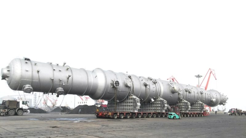
Tray spacing, tray type (valve, sieve, bubble-cap), downcomer area, and the number of theoretical stages are all interdependent. A fabricator needs the vapor and liquid traffic profiles — not just an inlet and outlet composition — to set shell diameter accurately. Column diameter in industrial service typically ranges from 0.6 m for small specialty columns to over 8 m for atmospheric crude distillation towers, and the difference between undersizing and correct sizing is the difference between meeting product spec and running the column flooded at reduced throughput.
For any separation vessel, feed composition, design throughput with its expected range of turndown, required separation efficiency, foaming classification, and pressure class must all be fixed before a fabricator can issue a meaningful quotation. Issuing an RFQ with open internals and unconfirmed flow data guarantees either a padded price covering the fabricator’s uncertainty or a vessel that requires field modifications during commissioning.
Heat Transfer Vessels: Shell-and-Tube Exchangers, Reboilers, and Condensers as Pressure-Rated Equipment
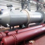
Shell-and-tube heat exchangers sit in a procurement grey zone that causes genuine confusion on EPC projects. Process engineers classify them as heat transfer equipment. Vessel engineers classify the shell as a pressure vessel. Both are correct — and that dual identity means the equipment must satisfy two overlapping regulatory frameworks simultaneously, which has real consequences for inspection scope, documentation, and fabrication lead time.
Independent Pressure Ratings on Each Side
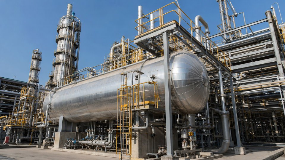
The shell side and tube side of a heat exchanger are, in code terms, two separate pressure-containing systems that happen to share a common boundary. Under ASME Section VIII and PED 2014/68/EU, each side carries its own design pressure, design temperature, material certification, and hydrostatic test pressure. A crude preheat exchanger might run 2.5 MPa on the shellside and 8.5 MPa on the tubeside — the shell is tested at 1.3× its design pressure while the tube bundle is tested independently at 1.3× its own rating. Mixing up these test pressures during commissioning can collapse tube-to-tubesheet joints or distort the shell, neither of which is a cheap fix.
Material grade divergence adds another layer. High-pressure, high-temperature tubeside service in hydrocarbon processing often demands low-alloy chromium-moly tubes (ASTM A213 T11 or T22), while the shellside — handling a cleaner utility fluid — uses carbon steel plate to SA-516-70. Inspectors must verify both material test reports independently. TEMA (Tubular Exchanger Manufacturers Association) classification — R for severe refinery service, C for general process, B for chemical service — defines the dimensional tolerances, corrosion allowances, and mechanical design margins that determine whether the equipment will last 25 years or start leaking at the tubesheet within three. Failure to state TEMA class in the purchase requisition is one of the most common and costly specification gaps on mid-scale EPC projects; the vendor defaults to the lightest class they can justify, and you find out at the first major turnaround.
Design Parameters That Drive Cost and Lead Time
Tube material selection is the single biggest cost lever. Carbon steel tubes for clean water or non-corrosive service run in the range of $15–35 per tube depending on wall thickness and length. Duplex stainless (UNS S31803) in chloride-bearing or acidic service can be 4–7× that figure. Titanium Gr. 2 tubes for seawater-cooled condensers or strongly oxidizing acids push further still — total bundle material cost can represent 50–65% of the exchanger’s fabricated price, depending on alloy, tube count, and current commodity pricing.
Bundle length and tube count matter because they directly set the fabrication shop’s constraint. Bundles exceeding 7–8 m require long mandrel equipment and specific handling rigs; not every fabricator has them, which shrinks your qualified vendor pool and stretches lead time from a typical 14–20 weeks into the 26–36 week range for large, long-bundle units. Floating-head configurations (TEMA AES or AET) allow thermal expansion without stressing the shell and enable bundle pull for cleaning — essential in fouling service. Fixed-tubesheet designs are cheaper and more compact but trap the bundle permanently, making mechanical cleaning on the shellside difficult or impossible. U-tube bundles split the difference on cost but cannot be cleaned on the tubeside by rodding, which disqualifies them from services with particulate fouling risk.
TEMA class must be explicitly stated in a heat exchanger purchase requisition; vendors will not default to the most conservative class.True
TEMA standard explicitly allows vendors to propose any applicable class unless the purchaser specifies otherwise. Defaulting to Class C instead of Class R reduces wall thickness and corrosion allowance, which shortens service life in demanding refinery or chemical service.
Procurement Red Flags Worth Flagging Before Order Placement
Three specification gaps generate the most post-order rework on heat transfer vessel packages.
Underspecified shellside nozzle loads. Piping connected to exchanger nozzles transmits forces and moments — thermal expansion of long runs, valve weight, support settlement. If the requisition does not state allowable nozzle loads, the fabricator designs to TEMA minimum, which is often inadequate for the actual piping configuration. The result: nozzle reinforcement pads added after fabrication, additional hydrotesting, and PWHT rework in some cases. Budget $8,000–$40,000 per occurrence depending on vessel size and re-inspection scope.
Missing vibration analysis for high-velocity gas service. Gas-to-gas exchangers and overhead condensers in high-velocity service are susceptible to flow-induced tube vibration. Tubes that vibrate against baffles wear through in 6–18 months. A proper vibration analysis per TEMA or HTRI software is a design deliverable, not optional. Requiring it in the requisition costs almost nothing; finding failed tubes at shutdown costs operational days and a full bundle replacement.
Fouling service undefined. Fouling factor selection affects the oversurface designed into the bundle. Too conservative and you pay for extra tubes and a larger shell. Too optimistic and the exchanger underperforms within months of startup, throttling downstream unit capacity. State the actual fouling factors per TEMA Table RGP-T-2.4 or provide process fluid characterization data; do not leave it to the vendor’s default.
Storage Vessels Under Pressure: Bullets, Spheres, and Intermediate Buffer Tanks
Pressurized storage is where process chemistry stops and inventory management begins — but the vessels involved are every bit as code-governed as the reactors upstream of them. Getting the vessel type wrong, or leaving scope gaps in the purchase order, creates problems that show up months after handover, usually during a PSM audit or the first seasonal demand spike.
Horizontal Bullet Tanks vs. Spherical Horton Spheres: Choosing the Right Form Factor
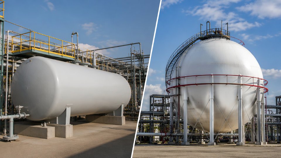
Horizontal bullets — cylindrical pressure vessels with hemispherical or ellipsoidal heads, mounted on saddle supports — are the standard choice for storage volumes in the 5–200 m³ range at pressures up to roughly 25 bar. They are shop-fabricated, shipped as single units, and set on relatively simple civil foundations. Cost per unit volume for a carbon steel bullet storing LPG typically runs 15–40% higher than for an equivalent sphere at the same total capacity, but that premium disappears at smaller volumes because spheres become impractical to fabricate and erect below roughly 300–500 m³.
Spherical tanks — Horton spheres — become the economic and safety choice once your storage requirement passes that threshold. A well-designed sphere at 1,000–10,000 m³ and 5–18 bar distributes membrane stress uniformly across its shell, which means wall thickness (and therefore material cost) is minimized relative to the volume stored. The trade-off is a large, fixed-position structure requiring substantial structural steelwork, a grillage or concrete ring foundation, and field erection with significant radiographic and PWHT requirements. For ammonia or LPG terminals handling regional distribution volumes, this is still the right answer — the cost per tonne of storage capacity drops sharply as volume increases.
Intermediate surge drums and pressure buffer vessels sit between these two categories. Sized typically at 1–30 m³, they serve process continuity rather than inventory: absorbing flow fluctuations between upstream reactors or separators and downstream units, preventing pressure transients from propagating through the system. Their pressure ratings vary widely depending on where they sit in the process — 3 bar on a low-pressure scrubber outlet, 150 bar on a high-pressure synthesis loop.
Regulatory and Safety Layers Buyers Cannot Shortcut
Pressurized storage vessels sit at the intersection of vessel codes and site-level process safety regulations, and both apply simultaneously. The vessel itself must be designed and stamped to ASME Section VIII (Div. 1 for most bullets and spheres), EN 13445, or GB 150 depending on the destination country and the EPC contract requirements. For above-ground atmospheric and low-pressure storage API 620 provides an alternative design basis, though most LPG and ammonia bullets exceed API 620’s pressure range and fall squarely under the pressure vessel codes.
Beyond the vessel stamp, pressurized storage on a chemical plant site typically triggers national pressure vessel registration — a pre-commissioning inspection and registration with the local authority having jurisdiction, whether that is a notified body under PED 2014/68/EU, a state boiler and pressure vessel board, or a provincial TSG authority. Skipping or delaying this step has stopped plant commissioning cold.
At the site level, OSHA PSM (in the US) and SEVESO III (in the EU) impose additional layers: consequence modeling, relief system documentation, and Management of Change requirements for any future vessel modification.
Pressure relief valve sizing for storage vessels can be based purely on fire case heat input without considering blocked-outlet scenariosFalse
API 520 and API 521 require evaluation of all credible overpressure scenarios — blocked outlet, external fire, thermal expansion of trapped liquid, control valve failure — and the relief device must be sized for the governing case, which is not always fire.
What to Specify in the Purchase Order Before the Fabricator Quotes
Scope gaps between the vessel fabricator and the site civil/mechanical contractor are where budgets fracture. A purchase order for a pressurized storage vessel should explicitly call out: insulation system type and thickness (cold service ammonia vessels require cryogenic-rated insulation plus a vapor barrier; LPG bullets in hot climates need reflective insulation to limit vapor pressure rise); pressure relief valve nozzle sizing per API 520/521 with the relief load calculation provided to the fabricator so nozzle reinforcement is adequate; the full instrumentation nozzle schedule including size, rating, orientation, and elevation for level gauges, pressure transmitters, and safety instrumentation; and cathodic protection requirements for buried or semi-buried bullets, specifying whether the system is sacrificial anode or impressed current and who is responsible for the junction box and test stations.
Leaving any of these to a “coordinate on site” resolution means change orders, schedule delays, or — worst case — a vessel that passes code inspection but fails the functional safety review because the relief nozzle is undersized for the actual blocked-outlet flow rate.
Surge, Buffer, and Accumulator Vessels: Stabilizing Process Continuity
Every experienced process engineer has watched a brand-new plant stumble through startup because the surge drum on the compressor suction was undersized by a well-meaning junior designer who treated it as a secondary line item. Surge drums, blowdown drums, pulsation dampeners, and accumulator vessels rarely appear in capital appropriation discussions the way reactors or columns do. They get specified late, sometimes bundled into compressor skid packages almost as an afterthought, and their sizing gets compressed under schedule pressure. The result shows up as compressor trips, hunting control loops, and repeated relief valve chatter within the first weeks of operation.
What These Vessels Actually Do
A surge drum sits between two process steps that operate at different and often variable flow rates — a feed pump and a downstream reactor feed system, for example, or a gas-liquid separator and a reciprocating compressor suction header. Its job is not to store product in any meaningful sense. It exists to absorb the mismatch. When upstream flow briefly exceeds downstream demand, liquid builds in the drum; when demand spikes, it draws down. The vessel gives the control system time to respond without the process seeing the disturbance.
Pulsation dampeners and gas accumulators serve an analogous function on the pressure side. A reciprocating compressor generates pressure pulses at its stroke frequency — typically 2 to 12 Hz depending on cylinder count and speed. Without adequate gas cushion volume downstream, those pulses propagate into connected piping, causing fatigue failures at small-bore branches, instrument connections, and heat exchanger nozzles. The accumulator absorbs the pulse energy by allowing slight gas compression and expansion across each stroke cycle.
Blowdown drums handle a different scenario: controlled depressurization of process systems to a safe collection point before venting or flaring, managing both the two-phase flow surge and the thermal load of flashing liquid.
Sizing Logic in Plain Engineering Terms
For liquid surge drums, residence time is the governing parameter. Most process engineering standards and the GPSA Engineering Data Book target 2 to 5 minutes of liquid residence time between the high-level shutdown setpoint and the low-level shutdown setpoint. The actual number depends on how responsive the upstream control loop is, how large a flow mismatch is credible, and what the consequence of running dry or flooding downstream means for the connected equipment. A pump-suction surge drum protecting a high-value centrifugal pump in a refrigeration circuit warrants the upper end of that range. A simple condensate collection drum in a low-stakes utility system can sit at the lower end.
For gas pulsation dampeners, sizing is driven by the ratio of dampener volume to compressor cylinder displacement volume, often referenced against API 618 pulsation analysis requirements for reciprocating compressors. A rule-of-thumb starting point from the GPSA data book is a dampener volume of roughly 10 to 15 times the single-cylinder displacement, though a full acoustic simulation — required under API 618 for most refinery and gas plant services — will refine that significantly. Skipping the simulation on a high-pressure hydrogen recycle compressor to save engineering cost is one of the more reliably expensive shortcuts a project can take.
Undersizing a compressor suction surge drum is a leading cause of reciprocating compressor trips during plant startupTrue
Insufficient liquid residence time causes the level control loop to lose authority during transient flow conditions, starving the compressor suction and triggering low-level shutdown — a well-documented startup failure mode in gas processing and petrochemical plants.
Procurement Considerations That Get Missed
These vessels are frequently procured inside compressor package or pump skid inquiries rather than through the main static equipment list, and that split in procurement responsibility creates gaps. The compressor vendor sizes the pulsation bottle to protect the machine; nobody independently checks whether the upstream surge drum protects the compressor vendor’s own sizing assumptions. Coordination between the rotating equipment engineer and the static vessel engineer needs to happen explicitly, not assumed.
Internal fittings deserve specific attention in the inquiry documents. A liquid surge drum on a wet gas service almost always needs a mist eliminator — a wire mesh pad or vane-type demister element — to prevent liquid carryover into the compressor suction. Omitting this from the purchase specification and discovering the need during pre-commissioning means either a vessel modification or an accepted risk of liquid slugging. Low-point drain nozzles sized for positive drainage without dead legs, level instrument bridles with isolation valves positioned for maintenance access, and pressure tap locations that avoid turbulent zones near inlet nozzles are all details that separate a well-procured surge drum from one that generates instrumentation headaches for its operational life.
Material selection for these vessels is usually straightforward — carbon steel with appropriate corrosion allowance covers most hydrocarbon and utility services — but cryogenic services such as ethylene or LNG demand low-temperature carbon steel or austenitic stainless, and sour gas service (H₂S above the NACE MR0175 threshold) requires full NACE compliance in both base metal and weld procedure qualification. Both conditions appear regularly in petrochemical and gas processing plants, and both conditions are easy to under-specify when the vessel is being bundled quietly into a rotating equipment package rather than reviewed as a standalone pressure vessel procurement.
Key Design Codes, Material Standards, and Third-Party Inspection Requirements Buyers Must Specify
Specifying the right design code is not a formality — it determines wall thickness, allowable stress, fabricator qualification requirements, and ultimately the landed cost of the vessel. Get this wrong at the inquiry stage and you will spend weeks resolving scope gaps after order placement, often at the fabricator’s change-order rates.
ASME Section VIII: Choosing the Right Division for Your Service
ASME Section VIII is the dominant code in international EPC procurement, and it has three distinct divisions that are not interchangeable.
Division 1 applies to the vast majority of industrial chemical plant vessels. It uses a design factor of 3.5 on tensile strength, which means it carries more conservatism and more material weight. For vessels operating at moderate pressures — broadly 0.1 MPa to around 20 MPa depending on geometry and temperature — and where detailed stress analysis is not warranted by budget or schedule, Division 1 is the practical default. Most fabricators in Asia, the Middle East, and Latin America are qualified to it.
Division 2 (Alternative Rules) uses a design factor of 2.4, permits higher allowable stresses, and requires a formal design-by-analysis approach including fatigue evaluation where cyclic loading applies. The result is a lighter vessel with thinner walls, which matters when you are specifying large-diameter high-pressure reactors in Cr-Mo alloy or where vessel weight affects structural steel costs. Division 2 fabrication demands more rigorous NDE and documented design calculations. Expect fabrication costs 15–35% higher than an equivalent Division 1 vessel, depending on complexity and the fabricator’s existing Division 2 program.
Division 3 covers ultra-high-pressure equipment above 700 bar (70 MPa). This is the territory of specialized synthesis reactors — urea autoclaves, certain polyethylene high-pressure reactors, and explosive-forming chambers. Few fabricators globally hold Division 3 certification. If your process falls in this range, qualify your supplier list before you issue the RFQ, not after.
For European-destined equipment, PED 2014/68/EU governs and requires CE marking through a Notified Body. PED categorizes vessels by fluid hazard group and PS×V product; higher categories mandate more rigorous conformity assessment routes. GB 150 is the Chinese national standard and is mandatory for vessels installed in China; it aligns structurally with ASME but carries its own material grades, inspection requirements, and TSG (Special Equipment Safety Technical Supervision) licensing that foreign fabricators must obtain if they want to ship to Chinese end users.
Material Traceability: What the Purchase Order Must Demand
Material fraud — substituted plate grades, missing heat numbers — is a real plant-floor risk, not a theoretical one. Every pressure vessel purchase order should explicitly require EN 10204 Type 3.1 Mill Test Reports (MTRs) as a minimum, meaning the material manufacturer certifies the heat analysis and mechanical properties. For pressure-containing components on critical service vessels, specify 3.2, which adds independent third-party verification of the MTR.
Positive Material Identification (PMI) using X-ray fluorescence or optical emission spectrometry should be specified on all alloy materials — any P-No. 4 through P-No. 11 base metals, any austenitic stainless, duplex, or nickel-alloy weld metal. PMI catches substituted filler wire before it is buried under weld cap passes.
Where the vessel will see temperatures below -20°C, require documented Charpy V-notch impact testing per ASME UG-84 at the minimum design metal temperature, with acceptance criteria written into the purchase order — not left to the fabricator’s interpretation. Weld Procedure Specifications (WPS) and Procedure Qualification Records (PQR) must be submitted before fabrication starts, not presented at final documentation handover.
Third-Party Inspection: Define Hold Points Before You Place the Order
Specifying the inspection and test plan (ITP) at inquiry stage — before order placement — is standard practice for EPC projects and prevents fabrication schedule disputes.True
EPC contractors universally require ITP agreement as part of technical bid clarification. Introducing hold points after order placement gives fabricators legitimate grounds to claim schedule impact costs, because production sequences may already be committed.
The distinction between an Authorized Inspection Agency (AIA) and an independent TPI matters commercially. An AIA — an organization like an ASME-authorized insurer — is required for ASME code stamping; the AI (Authorized Inspector) must witness certain code-mandated inspections and sign the Data Report. An independent TPI (Bureau Veritas, TÜV, Lloyd’s Register, or a project-owner-nominated inspector) represents the buyer’s interests on top of code compliance. Both can and often should be present simultaneously on critical vessels.
Your ITP should classify each inspection activity as either an H (Hold Point — fabrication cannot proceed without inspector sign-off) or a W (Witness Point — inspector is notified and should attend, but work can proceed if they do not). Define R (Review) for document checks. Typical hold points on a high-pressure vessel include material identification before cutting, fit-up before welding, post-weld heat treatment (PWHT) chart review, and hydrostatic test. Releasing hold points to witness points to reduce cost is a legitimate procurement lever — but do it consciously, in writing, with your engineering team’s sign-off, not because someone forgot to specify them.
Inspection level should appear in the RFQ technical specification, not the commercial terms. A fabricator pricing Level II inspection (two hold points, dimensional survey, final documentation review) will price differently from one pricing Level III (full surveillance including welder qualification verification, in-process weld monitoring, NDE witness). That cost difference — typically ranging from 1.5% to 4% of vessel value depending on vessel criticality and geographic location of the shop — is far smaller than the cost of a field repair or a vessel rejection at the destination port.
How EPC and Owner-Operator Buyers Should Structure a Pressure Vessel Requisition
A poorly assembled RFQ costs more than the time it wastes. Vendors quote to what you give them. If your package omits design pressure basis, corrosion allowance source, or inspection category, every bidder fills those gaps with different assumptions — and you get bids that look comparable but aren’t. Change orders follow, and on a critical-path item with a 16–28 week fabrication lead time, a single late clarification round can push mechanical completion by months.
Mandatory Technical Documents the Package Must Include
The process datasheet is the non-negotiable anchor. It should state fluid composition (including trace components that drive material selection — chlorides, H₂S, amine concentration), operating pressure and temperature, design pressure and temperature with the basis for each uplift, flow rate or inventory volume, and phase behavior at operating conditions. Without fluid composition, no competent fabricator can confirm cladding requirements or select the right weld procedure.
The vessel datasheet covers geometry, nozzle schedule (size, rating, facing, orientation), insulation type and thickness, weight limits for shipping and installation, and any platform loading restrictions. Nozzle orientation drawings save a disproportionate amount of back-and-forth — a simple top-view orientation sketch eliminates ambiguity that would otherwise generate five RFIs.
Specify the applicable design code explicitly: ASME Section VIII Division 1, Division 2, PED 2014/68/EU, GB 150, or a combination where the destination country mandates local registration. State the inspection category or class — ASME U-stamp, CE marking with notified body involvement, or a national registration mark such as TS (China) or DOSH (Malaysia). If the project spec requires Third Party Inspection by a named agency, name it in the RFQ; the fabricator’s quality plan and witness hold points must be built around that agency’s schedule availability.
Commercial Terms That Directly Shape Cost and Lead Time
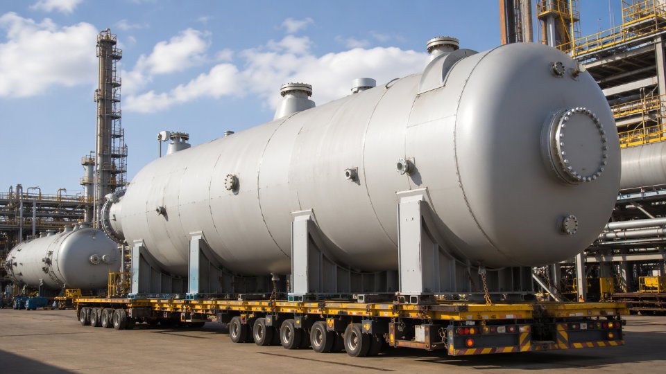
Delivery point is not a minor administrative detail. Ex-works shifts all export crating, port handling, and freight risk to the buyer. CIF named port shifts those costs to the vendor — and some fabricators in lower-cost regions carry thin margins and inflate CIF pricing to cover freight uncertainty. For large vessels over roughly 15 tonnes or with an over-dimensional profile, specify the required transport mode (flat-rack, heavy-lift vessel) and confirm whether vendor’s price includes export customs documentation.
Surface preparation and coating specification should reference NACE No. 1 / SSPC-SP 5 (white metal blast) or SSPC-SP 10 (near-white) with explicit DFT requirements by coat, not a generic “painted to manufacturer’s standard.” That phrase means nothing across different fabrication countries. If the vessel will be insulated, specify an insulation primer system; coating failure under insulation is one of the more expensive and slow-to-diagnose forms of external corrosion.
The Manufacturer’s Data Record (MDR) content list must be itemized in the purchase order, not left to the vendor’s interpretation. A minimum MDR for a coded vessel should include mill test reports with heat traceability, weld maps, WPS/PQR records, RT/UT/PT film or digital records, PWHT charts, hydrostatic test records, and the stamped data report (U-1 form for ASME). Scope creep on documentation is common; getting the list agreed before order placement avoids disputes at mechanical completion when the MDR is a prerequisite for commissioning sign-off.
Evaluating and Comparing Bids Without Getting Misled
Wall thickness shown on a vendor's bid drawing confirms code compliance.False
A bid drawing shows proposed thickness, but compliance is only confirmed by a complete design calculation package referencing the specified code edition, including corrosion allowance, joint efficiency, and nozzle reinforcement — none of which appear on a drawing alone.
When reviewing technical submissions, pull the wall thickness calculation and confirm which code edition and allowable stress table the vendor applied. Older editions carry different allowable stresses for the same material. Check that the corrosion allowance matches the value in the process licensor’s data sheet, not a rounded-down figure the vendor inserted to thin the shell. Nozzle reinforcement calculations are frequently missing from first-round bid packages — their absence usually means they haven’t been done yet, which is a scope risk, not a minor document gap.
Supplier qualification should be verified against the ASME QC manual revision on file with the National Board, not the certificate copy the vendor emails. ISO 9001 certification alone does not qualify a fabricator for coded pressure vessel work; the ASME QC manual and current authorizations are the governing documents. A fabricator with ISO 9001 but an expired or limited ASME certificate scope has failed a basic qualification filter that a surprising number of project teams miss under schedule pressure.
Frequently Asked Questions About Pressure Vessels in Chemical Plants
What is the difference between a pressure vessel and a process vessel?
The terms get used interchangeably on plant floors and in vendor catalogs, which creates real compliance problems. A pressure vessel has a precise regulatory meaning: any closed container designed to hold fluids at a pressure meaningfully above or below atmospheric — in most codes, the threshold sits at 0.1 MPa gauge (ASME Section VIII sets its own scope boundaries based on pressure-diameter products). A process vessel is a commercial description. It encompasses everything from an open atmospheric mixing tank to a high-pressure reactor. Every pressure vessel is a process vessel. Most process vessels are not pressure vessels in the code sense.
Why does this matter? Insurance underwriters, inspection authorities, and plant operating licenses treat code-stamped pressure vessels differently from atmospheric equipment. If a procurement team specifies a “process drum” without flagging the design pressure, a fabricator may quote to a structural standard rather than ASME VIII or GB 150 — and the resulting vessel will not pass the authorized inspector’s review. Change orders at that stage are expensive. Get the operating and design pressure on the RFQ cover sheet, always.
Which pressure vessel code should I specify for a project in Southeast Asia or the Middle East?
ASME Section VIII Division 1 with the U-stamp is the closest thing to a universal default in GCC countries (Saudi Arabia, UAE, Kuwait) and across most of ASEAN. Most engineering authorities and end-clients in those regions accept it without additional negotiation, and the pool of ASME-certified fabricators is large enough to get competitive bids.
The picture changes as soon as the project touches certain jurisdictions. India applies IBR (Indian Boiler Regulations) to steam-service vessels and frequently requires local third-party inspection bodies regardless of the base code. South Korea mandates KGS certification for vessels installed in Korean-regulated facilities. Projects destined for Chinese plants or involving Chinese EPC contractors almost always require GB 150 compliance and TSG 21 registration — a process that involves the local special equipment inspection institute and cannot simply be substituted with a U-stamp after the fact.
ASME U-stamp is automatically accepted in all international jurisdictionsFalse
Several countries including India, China, and South Korea either mandate their own national codes or require additional local certification steps that a U-stamp alone does not satisfy. EPC contractors must verify regulatory authority requirements before issuing any RFQ.
The practical rule: confirm the end-client’s country of installation and the applicable regulatory authority before the RFQ goes out. Changing the code requirement after fabrication begins is not a paperwork problem — it can mean re-inspecting or re-stamping welds, or in the worst case, scrapping completed sections.
How long does it typically take to fabricate a custom pressure vessel?
Lead times vary widely depending on geometry, material, and shop backlog. A straightforward carbon steel separator or surge drum with standard nozzle configurations: 8–14 weeks from purchase order to factory acceptance test. A reactor in 2205 duplex stainless or with explosion-bonded clad lining: 20–40 weeks, driven largely by raw material procurement and PWHT queue time at the shop. A large-diameter distillation column with structured packing, draw trays, and multiple manways: 30–52 weeks, where the internal hardware often sits on the critical path ahead of the shell itself.
Three factors consistently push lead times past initial estimates. First, alloy plate and forged nozzle material procurement — Cr-Mo grades and nickel alloys have long mill lead times that vary with global order books. Second, third-party inspection scheduling: an authorized inspection agency (AI) slot at a busy fabrication shop may add two to four weeks between weld completion and final hydrostatic test. Third, post-weld heat treatment: shops with limited furnace capacity queue PWHT runs, and a vessel waiting for furnace time can sit idle for weeks.
What causes most pressure vessel failures in chemical plants, and how does proper specification prevent them?
Stress corrosion cracking (SCC) tops the list in chemical service, particularly in chloride-containing environments attacking austenitic stainless steel and in wet H₂S service attacking carbon steel. Specifying the correct alloy for the actual process fluid — not a generic “stainless steel” call-out — is the buyer’s primary lever. Hydrogen embrittlement is the dominant failure mode in high-pressure hydroprocessing and ammonia synthesis vessels; it is prevented by specifying NACE MR0175/ISO 15156 compliance and hardness limits on weld heat-affected zones, then verifying with hardness testing during inspection.
Fatigue cracking at nozzle junctions is common where vessels experience cyclic pressure loading and the nozzle reinforcement was undersized or the weld profile was left as-welded rather than ground flush. A well-written requisition specifies the number of pressure cycles expected over the design life — not just the maximum design pressure. Inadequate corrosion allowance is a specification failure, not a fabrication failure: if the buyer provides a corrosion rate assumption that turns out to be too low, the vessel reaches minimum wall thickness years ahead of schedule.
Can a single fabricator supply all five types of pressure vessels covered in this article?
Some can, but most shops have genuine strengths in one or two categories and real limitations in others. A shop equipped for large-diameter storage spheres likely has the crane capacity and field-weld capability for that work — but may lack the precision machining centers needed for tight-tolerance reactor internals. Conversely, a fabricator that excels at autoclave reactors in exotic alloys may have a 50-tonne shop crane limit that rules them out for a 200-tonne distillation column.
When qualifying a fabricator for a multi-category order, review four things: shop equipment list (maximum plate rolling diameter and thickness, furnace dimensions for PWHT, NDE equipment on-site versus subcontracted), certified welder headcount by process (GTAW, SAW, SMAW — a short-staffed shop will miss your schedule), maximum single-lift and transport envelope (oversized column sections require route surveys and special permits that some shops have never managed), and a reference project list filtered to vessels similar in size, pressure class, and material to what you are buying. A fabricator who checks all four boxes for reactors but has never shipped a column over 3 meters in diameter is a real risk on a grassroots unit procurement.