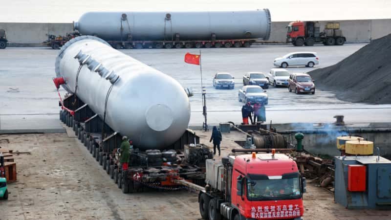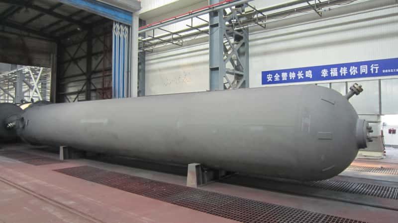

Specifying a pressure vessel without confirming PWHT requirements upfront is one of the fastest ways to blow a fabrication schedule. A vessel that reaches the hydro-test stage and is then flagged for missed post-weld heat treatment doesn’t get a quick fix — it goes back into the queue, the certifying inspector walks, and delivery slips by weeks or months. On large-diameter vessels with wall thicknesses above 38 mm, that rework can consume the entire cost margin on the order.
PWHT is mandatory for custom pressure vessels when wall thickness, service conditions, material type, or applicable code triggers a specific requirement. Under ASME VIII Div.1, carbon steel (P-No.1) groove welds in vessels with nominal thickness exceeding 1.5 in (38 mm) require PWHT at 1100–1200°F (593–649°C), held for a minimum of one hour per inch of thickness. Additional triggers include hydrogen service, low-temperature ratings, certain alloy steels, and jurisdictional amendments regardless of thickness.
What makes PWHT decisions genuinely difficult in custom vessel fabrication is that the thickness rule is only the starting point. A vessel running at modest pressure with a wall that barely clears the threshold might look straightforward, but the moment the process engineer adds an H₂S service designation or the owner spec references NACE MR0175, the heat treatment obligation changes completely — and so does the inspection sequence, the cost projection, and the delivery window you quoted.
Code-Mandated PWHT Triggers: What ASME VIII Div.1, EN 13445, and GB 150 Actually Require
Procurement teams and project engineers often treat PWHT as a binary yes/no checkbox on a datasheet. The reality is more granular — each code sets its own combination of thickness thresholds, material group classifications, service conditions, and minimum temperature holds, and missing any one of those variables at the RFQ stage can force a mid-fabrication design revision that costs you weeks.
ASME VIII Division 1 — UCS-56 Thickness-Based Triggers by P-Number
UCS-56 is the primary mandatory PWHT table for pressure vessels built to ASME Section VIII Div.1. The triggering variable is nominal thickness at the weld joint, not overall vessel wall thickness, which catches fabricators off-guard when nozzle reinforcing pads or saddle attachment welds push local thickness above a threshold even when the shell itself is below it.
For P-No.1 carbon steel (plain carbon and carbon-manganese steels like SA-516-70, SA-106-B), PWHT is mandatory when the nominal weld thickness exceeds 1.5 in (38 mm). Holding temperature runs 1100–1200°F (593–649°C), and hold time is 1 hour per inch of thickness, with a 15-minute minimum regardless of thickness. These figures hold for most groove welds; fillet welds follow a separate throat-thickness check.
The thresholds tighten considerably as alloy content rises. P-No.3 steels (alloy steels like SA-387 Grade 11) require PWHT at nominal thickness above 0.625 in (16 mm) for most applications. P-No.4 and P-No.5A/5B Cr-Mo grades — 2.25Cr-1Mo (SA-387 Grade 22), 5Cr-0.5Mo, and 9Cr-1Mo — carry mandatory PWHT regardless of thickness for many weld configurations. That “regardless of thickness” clause is where procurement teams get tripped up: a 12 mm wall vessel in P91 material still requires PWHT, period, and no exemption exists for thin-wall construction.
ASME VIII Div.1 UCS-56 requires PWHT for P-No.1 carbon steel groove welds exceeding 1.5 in (38 mm) nominal thicknessTrue
UCS-56 Table UCS-56 explicitly lists P-No.1 with a 1½ in mandatory PWHT threshold for most groove welds; this is a direct code requirement, not an interpretation.
EN 13445-4 Chapter 9 — European Ferritic Steel Requirements
EN 13445-4 takes a different approach. Rather than purely thickness-based triggers, Chapter 9 links mandatory PWHT to a combination of wall thickness, material group (as defined in EN 13445-2, broadly mapping to CEN/TR 15608 groupings), minimum preheat temperature, and heat input control during welding. The interaction matters operationally: a fabricator who increases preheat to the EN 13445 minimum for a Group 2 ferritic steel in the 30–35 mm thickness band may be able to defer mandatory PWHT, but only if heat input per pass also meets the specified ceiling. On larger shells — say, a 2,400 mm diameter vessel with complex nozzle clusters — maintaining consistent heat input across multiple welding stations in a busy shop is harder than it looks on paper, and many European fabricators simply schedule PWHT rather than risk a non-conformance finding at final inspection.
For Group 1 (non-alloyed and fine-grain steels comparable to P-No.1), the general EN 13445 threshold aligns roughly with ASME at around 35 mm, but national annexes — particularly for hydrogen service or cyclic pressure loading — can lower that trigger or make PWHT unconditional.
GB 150.4 — Chinese National Standard and Its Export Project Implications
GB 150.4 governs vessels fabricated in China and exported under EPC contracts to Southeast Asian, Middle Eastern, and African projects. For carbon steel, the mandatory PWHT threshold largely mirrors ASME at 32–38 mm depending on steel category, but GB 150 is stricter than ASME for low-alloy grades in the 16MnR and 15CrMoR families. These steels, widely used in Chinese fabrication shops, require PWHT at thicknesses above 30 mm (approximately 1.18 in) — a meaningful difference if your design sits between 30 mm and 38 mm and the EPC client assumes ASME equivalence.
GB 150.4 also mandates PWHT for vessels in hydrogen service above certain partial pressure thresholds independent of thickness, which aligns with NACE/API 941 Nelson curve logic but is encoded directly into the fabrication standard rather than left to the vessel engineer’s judgment.
Side-by-Side Code Comparison
| Material Group | Code | Mandatory PWHT Thickness Trigger | Holding Temperature Range | Minimum Hold Time |
|---|---|---|---|---|
| Carbon steel (P-No.1 / Group 1 / Q245R–Q345R) | ASME VIII Div.1 | >1.5 in (38 mm) nominal weld thickness | 1100–1200°F (593–649°C) | 1 hr/in, min 15 min |
| Carbon steel ferritic | EN 13445-4 | ~35 mm (national annex may tighten) | 530–620°C (depends on steel sub-group) | 2–4 min/mm, min 30 min |
| Carbon steel / 16MnR | GB 150.4 | >32–38 mm (steel category dependent) | 600–640°C | 1 min/mm, min 30 min |
| Low-alloy Cr-Mo (P-No.4, 15CrMo / 1.25Cr-0.5Mo) | ASME VIII Div.1 | >0.625 in (16 mm) | 1200–1400°F (649–760°C) | 1 hr/in, min 15 min |
| Low-alloy 15CrMoR | GB 150.4 | >30 mm | 690–730°C | 1 min/mm, min 60 min |
| 2.25Cr-1Mo (P-No.5A / SA-387 Gr.22) | ASME VIII Div.1 | Any thickness (many weld types) | 1300–1400°F (704–760°C) | 1 hr/in, min 15 min |
What each figure depends on: temperature ranges vary based on exact chemistry heat, actual thickness at the thickest weld, and furnace uniformity zone certification. Hold times for EN 13445 increase under cyclic service annexes. GB 150 hold times for heavy-wall vessels above 100 mm are extended per supplementary welding procedure requirements.
An operational warning here: if your vessel is dual-stamped or designed to one code but fabricated in a shop certified to another, the more conservative requirement governs each specific attribute. A vessel designed to ASME but fabricated in a Chinese shop operating under GB 150.4 supervision for an EPC client requiring both stamps will typically need to satisfy whichever threshold triggers first — in practice, this often means the GB 150.4 lower threshold for low-alloy grades drives the PWHT schedule, adding furnace time that wasn’t in the original ASME-only cost estimate.
Material-Specific PWHT Requirements: Carbon Steel, Low-Alloy, Cr-Mo, and Stainless Cladding
Thickness alone does not tell the full story. Base metal chemistry — and what happens to the heat-affected zone (HAZ) during welding — often forces PWHT on vessels where the wall measurement alone would let you walk away without it. Procurement teams that treat PWHT as a simple thickness-trigger checklist tend to get surprised mid-fabrication, when the WPS review flags a mandatory thermal cycle the budget never accounted for.
Cr-Mo Alloy Steels: Temper Embrittlement and Creep Concerns
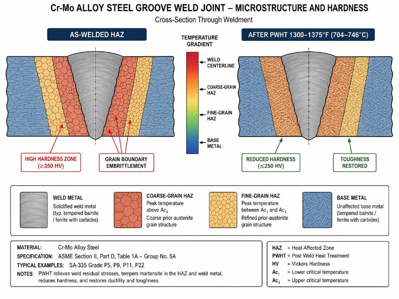
1.25Cr-0.5Mo (P-No.4) and 2.25Cr-1Mo (P-No.5A) are the workhorses of high-temperature reactor service — hydroprocessing reactors, high-pressure separators, catalytic reformer vessels. Both grades develop a coarse-grained, hardened HAZ after welding that is genuinely brittle at ambient temperature if left untreated. ASME VIII Div.1 and ASME VIII Div.2 both treat PWHT as essentially unconditional for these P-numbers regardless of thickness; the code minimum holding temperatures typically run 1300–1375°F (704–746°C) for P-No.5A, considerably higher than carbon steel requirements, with soak times that scale by thickness.
The engineering reason is not just immediate hardness. Cr-Mo steels in service above roughly 750°F (400°C) are susceptible to temper embrittlement — a time- and temperature-dependent migration of tramp elements (phosphorus, tin, antimony) to grain boundaries that raises the ductile-to-brittle transition temperature. A vessel that skips PWHT or uses an inadequate soak time enters service with a HAZ that may survive startup but becomes progressively more brittle over years of thermal cycling. The consequence is delayed cracking risk during an unplanned shutdown when the vessel cools rapidly. Catching that on an in-service inspection is expensive; catching it during a failure is catastrophic.
Wet H2S Service and the HIC Problem in Carbon Steel
This is where many carbon steel vessels get caught by requirements that go beyond ASME UCS-56 thickness triggers. NACE MR0103 (now ISO 17945) environments — any wet hydrogen sulfide service above roughly 50 ppm H2S in the water phase — create conditions for hydrogen-induced cracking and sulfide stress cracking in the HAZ. Carbon steel vessels in amine units, sour water strippers, and H2S scrubbers routinely fall below the 1.5 in (38 mm) ASME PWHT threshold, yet PWHT is still specified. The reason: PWHT drives HAZ hardness below the HIC-critical ceiling, typically targeting ≤200 HB (or ≤248 HV in some specifications), which significantly reduces hydrogen uptake sites at grain boundaries.
PWHT alone guarantees HIC immunity in wet H2S carbon steel vesselsFalse
PWHT reduces HAZ hardness and residual stress, lowering HIC susceptibility, but material selection (low-sulfur, low-CE heats), PWDE testing, and proper PWHT execution are all required together. PWHT performed outside specified temperature windows or with inadequate hold time can leave localized hard zones.
Specifying PWHT for wet H2S service needs to be captured in the project MDMT and materials requisition at the inquiry stage. Fabricators quoting without that requirement baked in will price lower and then negotiate change orders once the WPS gets reviewed against the process datasheet.
Clad and Weld-Overlay Vessels: Base Metal Still Governs
Austenitic stainless overlay — whether applied by weld overlay or explosion bonding — does not exempt the carbon steel or low-alloy shell from its own PWHT requirements. The base metal P-number drives the thermal treatment decision. A 2.25Cr-1Mo shell with 316L weld overlay still needs full PWHT at P-No.5A conditions. The overlay is applied first in some shop sequences, then the vessel undergoes PWHT, then the overlay is inspected for interlayer disbondment using UT or bond shear testing.
The scheduling risk here is real. PWHT after overlay means the thermal cycle must stay within a window that does not sensitize the austenitic layer — generally avoided by keeping the PWHT temperature below the sensitization range of 800–1500°F (427–816°C). For 321 or 347 stabilized grades this is manageable. For standard 304L or 316L, the fabricator needs to document the actual time-at-temperature carefully, because prolonged hold times in the sensitization range will destroy the overlay’s corrosion performance in the same pass that relieves residual stress in the shell.
Duplex Stainless and Titanium Linings: When PWHT Is the Wrong Answer
Duplex stainless steel (UNS S31803, S32205) and titanium-lined vessels represent cases where PWHT is typically prohibited rather than required. Duplex grades depend on a tightly controlled austenite-to-ferrite ratio of roughly 40–60%. Exposure above approximately 570°F (300°C) for any extended period precipitates intermetallic phases — sigma and chi — that destroy both toughness and corrosion resistance. PWHT at carbon steel temperatures would ruin the material outright.
For these vessels, residual stress management shifts to controlled interpass temperature limits (typically ≤300°F / 150°C maximum), qualified WPS with strict heat input controls, and post-weld solution annealing where necessary — a different thermal process entirely, conducted at 1900–2050°F (1040–1120°C) with rapid quench. Titanium linings face similar constraints: titanium becomes oxygen-embrittled above roughly 1100°F (593°C) in open atmosphere, making any conventional PWHT cycle destructive to the lining.
The practical procurement warning is this: if a vendor quotes PWHT on a duplex or titanium-lined vessel without flagging the conflict, their engineering review is not current. That is a qualification red flag worth chasing before award.
Engineering Design Factors That Trigger or Exempt PWHT Beyond Thickness Alone
Thickness gets most of the attention in PWHT discussions, and for good reason — it’s the most visible threshold in UCS-56. But experienced fabricators know that wall thickness is often not the deciding factor on the shop floor. Joint category geometry, service temperature requirements, mixed P-number combinations, and repair weld scenarios regularly push vessels into mandatory PWHT territory even when the nominal shell thickness sits comfortably below the code trigger point. If your procurement team or EPC design reviewers aren’t asking about these factors during the design review stage, you’re likely to discover the requirement — and its cost impact — after the weld map is already approved.
Category D Nozzle Attachments and the UCS-56(d) Trap
A full-penetration nozzle-to-shell weld classified as Category D carries its own PWHT consideration under ASME VIII Div.1 UCS-56(d). The rule evaluates the thickness at the weld, not just the shell nominal thickness. Reinforcing pad welds, insert plate configurations, and heavily reinforced nozzles can create a local weld thickness — measured as the lesser of the shell thickness or nozzle neck thickness at the joint — that crosses the 1.5 in (38 mm) threshold even when the main shell plate is, say, 32–35 mm. A vessel that passes a quick thickness check at the plate procurement stage can fail it at the nozzle detail stage. Catching this during preliminary design review costs nothing. Catching it after the nozzle forging is already machined and fit up means either a weld procedure revision or an unplanned furnace cycle.
MDMT, Charpy Testing, and the Low-Temperature Service Link
Vessels specified for low-temperature service — cryogenic separators, propane storage, cold-climate gas processing equipment — often require PWHT not because of thickness alone but because of Charpy impact test requirements tied to the Minimum Design Metal Temperature (MDMT). Under ASME UCS-66 and UCS-67, impact testing can be avoided only within defined thickness and temperature curves. PWHT shifts those curves: it can allow a lower MDMT without impact testing, or it can be the mechanism by which an as-welded heat-affected zone achieves acceptable notch toughness when impact testing is specified. In practical terms, if your vessel is designed for service below roughly -20°F (-29°C) and the material selection wasn’t finalized with the PWHT interaction in mind, you may face a late-stage decision between specifying full PWHT, upgrading to a tougher base material, or accepting mandatory Charpy qualification — each of which carries schedule and cost consequences ranging from a few thousand dollars in testing to 1–3 weeks of additional furnace and inspection time.
Dissimilar P-Number Welds: The Higher Number Governs
When a P-No.1 carbon steel shell is welded to a P-No.5 Cr-Mo alloy nozzle or transition piece, the PWHT requirement for the entire weld joint is governed by the higher P-number — the Cr-Mo side. P-No.5 materials typically require PWHT holding temperatures in the range of 1300–1400°F (704–760°C), which is significantly above the 1100–1200°F range used for carbon steel. Running the whole vessel through a higher-temperature cycle to satisfy one nozzle attachment is rarely practical and can over-temper carbon steel components. The typical resolution is local PWHT using resistance heating or induction blankets focused on the dissimilar weld zone, but this requires qualified procedures, calibrated thermocouples placed per the code, and documented heat soak gradients — work that must be scoped and priced before the purchase order is placed, not after.
Repair Welds and Field Erection Welds
Repair welds — including those made to correct fit-up defects, porosity, or dimensional nonconformances — are subject to the same PWHT rules as the original production welds under most code interpretations and most owner specifications. A shop repair on a P-No.1 vessel that has already completed furnace PWHT can require a second full or local thermal cycle, which is where schedule impacts become severe. Field erection welds on large towers or reactors assembled on-site present a logistically harder version of the same problem. Local PWHT using flexible ceramic pad heaters is the standard approach, but soak band widths, gradient control, and thermocouple placement must comply with ASME requirements and are frequently underestimated in contractor field execution plans.
A single unplanned local PWHT cycle on a field-erected vessel can add 3–7 days to mechanical completion, depending on vendor mobilization time and the number of weld joints requiring treatment.True
Local PWHT on-site requires mobilization of qualified heating equipment and personnel, procedure qualification documentation, and witness inspection — each adding elapsed time independent of the actual heating cycle duration, which itself runs 8–24 hours per joint depending on thickness and cooling rate requirements.
The practical takeaway for procurement and design review teams: request a PWHT impact assessment as a formal deliverable from the vessel designer before the fabrication drawing is issued for approval. Ask specifically about nozzle attachment categories, any service temperatures below ambient, mixed material grades at any weld joint, and the contractor’s repair weld procedure. These four questions will surface the vast majority of non-obvious PWHT requirements before they become schedule line items.
PWHT Methods for Large Custom Vessels: Furnace, Local, and Internal Firing Compared
Choosing the wrong PWHT method doesn’t just create a code compliance headache — it can stall a vessel in the shop for weeks, generate rejected thermograph records, or worse, produce a heat treatment that looks acceptable on paper but leaves residual stress gradients that cause cracking in service. For large custom vessels, the execution method is a project-critical decision that procurement teams and project engineers need to lock down early, not after the vessel is already sitting in a fabricator’s yard.
Full Furnace PWHT: The Benchmark Method
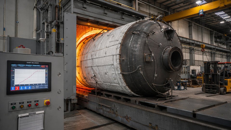
Furnace treatment gives you the most uniform soak temperature across the entire weldment, which is why most codes and most quality engineers default to it when the vessel geometry permits. A well-calibrated car-bottom furnace can hold temperature uniformity within ±14°C (±25°F) across the load, which satisfies ASME VIII Div.1 requirements and simplifies thermocouple documentation considerably. Major heavy-fabrication shops operate furnaces ranging from small batch units up to roughly 25–30 m in length and 6–8 m in usable cross-section, which covers the majority of refinery and petrochemical vessels. Beyond those dimensions, you’re looking at field heat treatment or sectional furnace runs with intermediate circumferential welds treated last — both of which add complexity.
The constraints are real. A vessel with a diameter over 5 m may not clear the furnace door even if the length fits. Shipping weight and transport route often determine whether a furnace-treated vessel can leave the shop intact, particularly for reactors above 300 metric tons. When logistics rule out furnace treatment, fabricators shift to the alternatives below.
Local PWHT with Electric Resistance Heating Bands
Local PWHT is code-permitted for specific joint configurations under ASME VIII Div.1 UW-40 and EN 13445-4 Clause 10, but the requirements on soak band width and gradient control zone are non-negotiable and frequently underestimated by fabricators under schedule pressure. ASME requires the heated band to extend at least one inch (25 mm) beyond the weld toe on each side — the actual soak band width must encompass the full weld cross-section plus heat-affected zone. The gradient control zone beyond the soak band is critical: too steep a thermal gradient between the heated zone and the ambient shell creates secondary thermal stresses that partially defeat the purpose of the treatment.
Thermocouple density matters enormously. Expect a minimum of one thermocouple per foot of circumference for large-diameter nozzle attachments, with third-party-witnessed chart records required for most pressure part welds. Calibration certificates for every thermocouple must be current — inspectors on ASME U-stamp vessels will reject records with expired calibration documentation, and rescheduling the heat cycle adds days.
Operational warning: local PWHT on a complex nozzle cluster — multiple nozzles within a short shell section — frequently produces overlapping gradient zones that are difficult to control simultaneously. In those cases, full furnace treatment is almost always the more defensible choice, even if it requires an additional shop move.
Internal Firing for Field-Erected Vessels
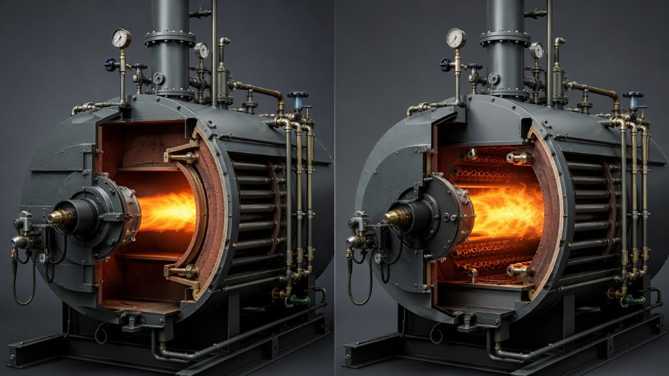
Large field-erected storage vessels, reactors, and absorbers that cannot be transported after fabrication are sometimes treated by internal combustion firing — a burner assembly introduced through a manway or nozzle, with the vessel shell acting as the furnace enclosure. Temperature control is inherently less uniform than furnace treatment. Hot spots near the burner flame can overshoot the upper holding temperature limit, potentially causing local overtemperature that degrades toughness in low-alloy steels.
Successful internal firing depends on burner placement geometry, refractory lining on internal surfaces if required, and adequate thermocouple coverage on the external shell — typically at multiple elevations and angular positions. Inspector access during the hold period is physically impossible, so witnessed thermocouple data acquisition with continuous chart recording is the only verification method. Some project specifications and owner engineering standards prohibit internal firing outright for Cr-Mo vessels; verify this before the method goes into the fabrication procedure.
Comparison: Selecting the Right Method for Your Vessel
| Method | Typical Applicable Vessel Size | Temperature Uniformity Risk | Relative Cost Factor | Schedule Impact | Code Acceptance Notes |
|---|---|---|---|---|---|
| Full furnace PWHT | Up to ~25–30 m length, ~5–6 m OD | Low (±14°C achievable) | Baseline (1.0×) | 3–7 days including loading/cooling | Universally accepted; preferred by most owner specs |
| Local electric resistance | Any size; limited to specific joint types | Medium — gradient control critical | 1.1–1.4× depending on thermocouple count | 2–5 days per heat zone; multiple zones multiply time | Permitted per UW-40 / EN 13445-4; restrictions apply to P-No.4/5 materials |
| Internal firing | Large field-erected vessels, typically >4 m ID | High — hot spot risk near burner | 0.9–1.2× (no furnace fee, but supervision cost is significant) | 5–10 days including setup and controlled cool | Code-permitted but owner specs frequently restrict or prohibit; verify early |
Local PWHT with electric resistance bands is always cheaper than furnace PWHT for large vessels.False
Cost depends heavily on the number of welds requiring treatment, thermocouple count, third-party witnessing fees, and the number of separate heat cycles needed. For vessels with many nozzles or complex joint configurations, the cumulative cost of local PWHT often meets or exceeds furnace cost — without the uniformity advantage.
The right method comes down to four variables: vessel geometry, material P-number, applicable code and owner specification restrictions, and shop or site logistics. Procurement teams that specify “PWHT required” on the data sheet without specifying the permitted method are leaving a significant cost and schedule variable entirely in the fabricator’s hands.
How PWHT Affects Inspection Sequence, NDE Scheduling, and Third-Party Witness Hold Points
Sequence errors in inspection planning are where PWHT most reliably converts a minor schedule buffer into a three-week delay. Most fabrication teams understand the metallurgical rationale for heat treatment. Fewer think through what PWHT does to the NDE schedule — and even fewer build third-party witness hold points around it correctly from the outset.
NDE Must Follow PWHT, Not Precede It
The instinct on a congested shop floor is to run radiographic testing or ultrasonic testing as soon as welds are complete, clear the paperwork, and treat PWHT as a finishing step. That sequence is wrong for code compliance and physically misleading. Under ASME VIII Div.1, final volumetric examination — whether RT or UT — must be performed on the post-PWHT weld. The reason is direct: PWHT relieves residual stress and can expose or alter discontinuities that were geometrically obscured or stress-masked in the as-welded condition. A film taken before heat treatment does not represent the final material condition the code is asking you to verify.
Hardness testing of the weld heat-affected zone carries the same constraint, and it is the one most often skipped prematurely. HAZ hardness on a carbon steel or Cr-Mo weld measured before PWHT will read 30–60 HV higher than post-treatment values, depending on preheat practice and heat input. If your acceptance criterion is 248 HV (a common cap for sour-service P-No. 1 material under NACE MR0175), a pre-PWHT hardness traverse tells you almost nothing useful. Inspectors who sign off hardness records before heat treatment is complete are generating paperwork, not quality assurance.
Third-Party Hold Points and Thermocouple Chart Review
Authorized Inspection Agencies — whether the ASME AI from a state-licensed insurer, Lloyd’s Register, Bureau Veritas, or TÜV — treat the PWHT heat treatment record as a mandatory hold point before the Manufacturer’s Data Report can progress toward stamp release. This is not a formality. The AI will review the strip-chart recorder output or digital time-temperature log against the qualified procedure: did the furnace reach the specified soak temperature band (for carbon steel P-No.1, typically 1100–1200°F / 593–649°C); was the hold time maintained for at least 1 hour per inch of governing thickness, with the 15-minute minimum; were heat-up and cool-down rates within procedure limits?
Thermocouple placement records matter too. A vessel with a 3,000 mm diameter and 60 mm wall requires multiple thermocouples distributed to prove temperature uniformity across the full cross-section. If the AI arrives for a witness point and thermocouple calibration certificates are expired, or the chart shows a temperature excursion mid-soak, the heat treatment cycle is rejected. That means re-PWHT and a full reset of all post-PWHT NDE. On a large vessel with long furnace queues, that reset can add two to four weeks.
Thermocouple calibration certificates must be current at the time of PWHT, not merely at the time of purchase, to satisfy ASME AI review.True
ASME Section V and typical AI practice require that measuring and test equipment be calibrated within the interval specified by the fabricator's QC program. Expired calibration invalidates the temperature record regardless of when the thermocouples were purchased.
Late Design Changes After PWHT: The Reinspection Trap
The scenario repeats itself across heavy fabrication shops with uncomfortable regularity. A process engineer requests an additional instrument nozzle after the vessel has completed PWHT and post-weld NDE. That nozzle weld is a new groove weld on a vessel where PWHT was mandatory. The fabricator now faces a choice between qualifying and executing a local PWHT repair procedure with its own thermocouple setup, witness hold, and re-NDE of the affected zone, or re-entering the furnace with the entire vessel.
Neither option is cheap. Local PWHT on a nozzle attachment adds anywhere from a few thousand to tens of thousands of dollars depending on vessel geometry, access, and whether the procedure is already qualified — and it resets the NDE clock on every weld within the affected heat band. The project manager who approved that “minor” late change without reviewing the heat treatment status of the vessel just bought a schedule problem.
The practical control is a formal design freeze tied explicitly to PWHT status. Before heat treatment begins, the drawing revision should be locked. Any change request after that point goes through an engineering review that includes the QC manager and the AI, not just the design office.
Documentation That Must Travel with the MDR
The Manufacturer’s Data Report package for a code-stamped vessel must include, at minimum: the original heat treatment procedure qualified to the applicable code, the as-run time-temperature strip chart or digital log with thermocouple identifications cross-referenced to their positions on a vessel sketch, calibration certificates for every thermocouple and recorder used, and the heat treatment report signed by a responsible engineer.
For vessels operating under owner-specified requirements — sour service, cyclic loading, cryogenic service — expect additional scrutiny. Some owners and EPCs require the heat treatment subcontractor (if PWHT is done off-site or by a specialist) to submit their own ISO 17663-compliant procedure as a separate document. Missing any of these records at final documentation review does not merely delay stamp release; it can require the AI to reinspect the vessel in person before the MDR is accepted, adding cost and time that has no recovery.
Get the inspection sequence right at the project kick-off meeting, not after the first NDE report comes back flagged.
PWHT’s Impact on Fabrication Schedule and Total Vessel Cost: What EPC Buyers Should Budget
Schedule overruns on pressure vessel packages rarely announce themselves at contract signing. They surface six weeks before a planned mechanical completion date, when a project manager discovers the vessel is sitting in a fabrication queue waiting for furnace access. PWHT is one of the most consistent contributors to that kind of late-stage surprise, and it deserves a line item in both the project schedule and the procurement budget from day one.
Where PWHT Eats Into Your Fabrication Schedule
The time impact is not just the heat treatment cycle itself. That is actually the smaller part. For a large-diameter vessel — say, a reactor shell in the 2,000–3,500 mm range with wall thickness above 50 mm — the controlled heat-up rate typically runs 50–150°C per hour depending on code requirements and material grade, followed by the mandatory hold period, then a controlled cool-down that can be equally slow to avoid introducing new thermal gradients. The full thermal cycle for a heavy-wall carbon steel or Cr-Mo vessel can run 18–36 hours of continuous furnace time.
What fabrication shops rarely volunteer in their proposals is furnace queue time. During periods of high shop loading — common when refinery turnaround seasons or large EPC waves overlap — shops with a single car-bottom furnace may have a two- to four-week backlog for PWHT slots. For vessels with multiple weld seams requiring staged treatment, or for equipment requiring PWHT after each major weld repair, that queue time compounds. A realistic schedule allowance for PWHT-related delays on large custom vessels is three to five weeks total, not the one-week figure that sometimes appears in optimistic fabrication plans.
Post-PWHT NDE adds another scheduling layer. Hardness surveys, any required PWHT-qualified radiographic or ultrasonic re-examination of weld seams, and dimensional re-checks after thermal cycling all need to be completed before the vessel moves to hydrostatic test. If a third-party inspector has a witness hold point at post-PWHT NDE — which is standard on most EPC projects — coordinating that availability adds further calendar time. Inspectors are not always available on 48 hours’ notice.
Quantifying the Cost Addition
For carbon steel vessels in the lighter wall range (25–50 mm), PWHT typically adds 3–8% to total fabrication cost. That range depends on vessel diameter, total weld length, whether furnace PWHT is possible or local PWHT is required, and whether the fabricator owns a furnace of adequate capacity.
The cost profile shifts significantly for heavy-wall low-alloy and Cr-Mo reactor vessels. On equipment with walls above 75–100 mm, the combination of longer hold times, larger furnace occupancy, more rigorous temperature uniformity requirements, and post-PWHT hardness verification routinely pushes PWHT cost to 12–15% of total fabrication cost. Local PWHT on complex nozzle clusters or saddle attachment welds — where flexible ceramic heating elements, insulation blankets, and multiple thermocouple circuits are required — can actually exceed the cost of furnace treatment for equivalent weld length, purely due to labor intensity and setup time.
The Subcontracted PWHT Risk That Proposals Don’t Mention
Fabrication shops routinely subcontract PWHT to specialist heat treatment companies when their in-house furnace capacity is insufficient.True
This is standard industry practice, particularly for large or oddly dimensioned vessels that exceed a shop's furnace envelope. It introduces a second quality control interface, transport risk, and a separate documentation chain that procurement teams should verify.
When a fabricator subcontracts heat treatment, the vessel physically leaves the shop or a third-party crew mobilizes on-site. Either scenario introduces logistics risk — transport damage to partially completed nozzles, loss of temperature chart traceability if documentation handoffs are informal, and a second quality system that may not be reviewed during vendor qualification. These are not hypothetical concerns; they are the kind of issues that generate NCR paperwork and delay final inspection sign-off.
What to Require in the Technical Proposal
Ask fabricators to declare, in writing during the bidding phase: the PWHT method they intend to use (furnace versus local), the furnace internal dimensions and rated capacity, whether PWHT will be performed in-house or subcontracted, and if subcontracted, the name and qualification status of the heat treatment provider. Require a preliminary PWHT procedure reference and confirm that furnace temperature uniformity surveys are current.
Buyers who treat this as boilerplate often discover mid-fabrication that the vessel exceeds the shop’s furnace envelope, triggering a subcontract arrangement — and a schedule revision — that could have been negotiated at contract award.
Common PWHT Non-Conformances Found During Vendor Audits and How to Prevent Them
Vendor audits of PWHT execution reveal the same failure patterns repeatedly — across regions, across shop sizes, and across code jurisdictions. Most of these non-conformances don’t announce themselves in the final paperwork. They’re buried in chart records, hidden in thermocouple placement sketches, or simply absent from the documentation package entirely. Buyers who wait until final inspection to scrutinize PWHT compliance are already too late.
Thermocouple Placement Failures
The most common finding in PWHT audits is thermocouple placement that doesn’t actually represent the weld zone or heat-affected area being treated. ASME VIII Div.1 and most equivalent codes require thermocouples to be located within the soak band — the region that must achieve and hold the required temperature — not just somewhere on the vessel surface near the weld. In practice, fabricators under schedule pressure sometimes attach thermocouples to areas that heat faster or retain heat better than the actual joint, producing chart records that look compliant while the critical weld zone never reaches holding temperature.
For a large-diameter vessel, say 3,000–4,000 mm shell diameter with multiple nozzle welds, the number of thermocouples required is not trivial. Code guidance and good engineering practice both point toward a minimum of one thermocouple per distinct weld zone, with additional coverage at thicker sections, nozzle reinforcing pads, and any area where geometry creates a heat sink. Audits frequently find two or three thermocouples deployed on a vessel where engineering judgment would call for six or more. The result is unverifiable thermal history across significant portions of the weldment.
Heat-Up Rate Exceedances
Exceeding the maximum heat-up rate — typically 200–300°F per hour (110–165°C per hour) above 600°F (315°C) for thick-wall carbon and low-alloy steel vessels — is a less visible but mechanically consequential non-conformance. Rapid, uncontrolled heat-up introduces differential thermal stress across a heavy wall section, potentially generating new residual stress rather than relieving existing stress. Chart recorders with coarse time resolution or automated furnace controls that aren’t properly tuned to the actual thermal mass of the loaded vessel can both contribute to this. A vessel with 75–100 mm wall thickness behaves very differently from a test piece, and furnace programs calibrated on lighter loads will overshoot on the ramp if not verified.
Furnace Temperature Uniformity Surveys
A furnace that hasn’t been surveyed for temperature uniformity within its calibration interval — typically every 6 to 12 months depending on the quality system — cannot be relied upon to deliver uniform soak conditions across the vessel length. This isn’t a theoretical concern. Hot and cold zones exist in every furnace; the question is whether they’ve been mapped and whether the loading arrangement accounts for them. If a fabricator cannot produce a current temperature uniformity survey showing acceptable variation (typically ±25°F / ±14°C across the working zone), the entire PWHT cycle performed in that furnace is of questionable validity. Re-treatment is the only defensible resolution, and that means schedule impact, potential re-NDE, and a difficult conversation about who bears the cost.
A furnace temperature uniformity survey is required at defined calibration intervals under most quality system standards, and an out-of-calibration furnace can invalidate a completed PWHT cycle.True
ASME and equivalent quality standards (e.g., ISO/IEC 17025 for calibration, NFPA 86 for furnace operations, and fabricator-specific ASME Quality System Certificates) require periodic temperature uniformity surveys. A furnace operating outside its verified calibration interval cannot demonstrate that the required soak temperature was achieved uniformly, which may necessitate re-treatment.
Falsified and Incomplete Chart Records
Time-temperature chart records are the documentary proof that PWHT occurred correctly. In regions where production pressure is high and third-party oversight is intermittent, falsified or reconstructed chart records are a known risk — not a hypothetical one. Common forms include re-drawn manual charts, digital records with implausibly smooth ramp profiles that don’t reflect real furnace behavior, and records that show correct holding temperature but lack continuous coverage of the heat-up and cool-down phases. A legitimate chart from a heavy-wall vessel in a large furnace will show some irregularity: minor oscillations during holding, asymmetric cool-down as the furnace door opens, thermocouple readings that converge gradually rather than instantly.
The most effective mitigation is third-party stage inspection with a hold point at PWHT execution, not just at record review. An unannounced audit during the actual heat treatment cycle, with the inspector physically verifying thermocouple attachment locations and witnessing chart initiation, closes the gap that document review alone cannot. This is worth specifying explicitly in the inspection and test plan (ITP).
Pre-Qualification Requirements Buyers Should Build Into Contracts
Before production begins, procurement documents and RFQ packages should require fabricators to submit the following for review and approval:
| Document | What to Verify |
|---|---|
| Furnace calibration certificate | Current, within required interval; covers working zone dimensions |
| Temperature uniformity survey | Acceptable variation across full working zone at representative load |
| Thermocouple calibration certificates | Individual calibration for each TC used in production |
| PWHT procedure (WPS-linked) | Heat-up rate, soak temperature range, hold time, cool-down rate, TC placement rules |
| Previous PWHT chart samples | Review for plausibility, completeness, and consistency with stated procedure |
Requesting these documents at RFQ stage — not after contract award — acts as a filter. Fabricators who cannot or will not produce current calibration records before they receive a purchase order will not improve their documentation practices once the order is placed. Schedule pressure only makes that situation worse.
A hold point for PWHT in the ITP, backed by contractual rights for the buyer’s inspector or an approved third party to witness and sign off before the cycle is considered complete, is the single most effective quality control measure available. Everything else — document review, procedure approval, audits — supports that hold point but doesn’t replace it.
Frequently Asked Questions About PWHT for Custom Pressure Vessels

Can PWHT Be Waived If Preheat Is Applied During Welding?
No — and this misconception causes real problems on the shop floor. Preheat slows the cooling rate through the martensite transformation range, reduces hydrogen cracking susceptibility, and lowers peak hardness in the heat-affected zone. It does all of that at the time of welding. PWHT works afterward, at a fundamentally different metallurgical mechanism: it tempers martensite that has already formed, relieves residual stress locked into the joint geometry, and reduces hardness across the full weld cross-section.
When ASME VIII Div.1 UCS-56 mandates PWHT because nominal thickness exceeds 1.5 in (38 mm) on a P-No.1 carbon steel groove weld, applying a preheat of 200–300°F (93–149°C) does not satisfy that requirement. The code specifies both, and the preheat requirement and the PWHT requirement exist independently. A fabricator who substitutes one for the other is producing a non-conforming vessel, regardless of what the WPS says about preheat practice. Buyers reviewing weld procedure submittals should confirm that both conditions are addressed explicitly rather than assuming one covers the other.
Does PWHT Weaken the Base Metal?
It can reduce tensile strength slightly, particularly in higher-strength low-alloy steels like SA-387 Gr.91 (9Cr-1Mo-V). In these materials, PWHT modifies the carbide precipitation state and can soften the base metal by 5–10% in tensile strength depending on temperature, hold time, and initial temper condition. For standard carbon steel grades — SA-516-70 being the most common pressure vessel plate — the effect is modest and well within the scatter accounted for in ASME allowable stress values, which are themselves derived from data that includes heat-treated material.
The trade-off is intentional and favorable. PWHT consistently improves Charpy impact toughness and reduces HAZ hardness. For any vessel designed to operate below the ductile-to-brittle transition temperature, that toughness improvement outweighs the minor strength reduction. A properly qualified WPS and PWHT procedure will have tested the post-PWHT mechanical properties, and the design allowable stress calculations should already reflect those values. If a fabricator is using pre-PWHT tensile properties as the design basis, that is an engineering error.
PWHT always significantly weakens pressure vessel base metalFalse
For standard carbon steel grades like SA-516-70, the tensile strength reduction after correctly controlled PWHT is modest and already accounted for in ASME code allowable stress values. The toughness improvement typically outweighs the minor strength reduction for vessels in low-temperature or cyclic service.
Is PWHT Required for Stainless Steel Pressure Vessels?
For austenitic grades — 304, 304L, 316, 316L — PWHT is not required and is actively harmful. Holding austenitic stainless steel in the 800–1500°F (427–816°C) range causes chromium carbide precipitation at grain boundaries, a condition called sensitization. Sensitized material loses intergranular corrosion resistance and becomes vulnerable to stress corrosion cracking in chloride or polythionic acid environments. If someone quotes PWHT on an austenitic stainless vessel as a standard line item, treat that as a red flag and ask for the technical basis.
Martensitic grades (such as CA-6NM used in pump casings and some pressure-retaining applications) and ferritic grades do require post-weld heat treatment, typically in the 1100–1300°F (593–704°C) range depending on composition, to restore toughness and reduce hardness. The rules differ substantially by grade, and the applicable code section and base metal P-number classification govern, not a blanket assumption.
Who Is Responsible for Specifying PWHT — the Buyer or the Fabricator?
Both parties carry responsibility, but for different scopes. The fabricator is accountable for meeting code minimums as defined by the applicable construction standard — ASME, EN 13445, or GB 150 — based on material, thickness, and joint configuration. That is non-negotiable and not subject to commercial pressure from schedule or cost.
The buyer’s engineering specification is the mechanism for imposing requirements beyond the code floor. Under ASME, the purchase order data sheet establishes service conditions, supplementary requirements, and any additional PWHT obligations. Under EN 13445, the User Design Specification carries that function. If the buyer’s process engineer knows the vessel will handle wet H2S, cyclic pressure, or hydrogen service but does not document those conditions in the specification, the fabricator has no code obligation to apply PWHT beyond standard thickness thresholds. The gap between what the code requires and what the service actually demands is the buyer’s risk to manage — and failing to close that gap in the specification is one of the more expensive procurement mistakes made on pressure vessel projects.
How Does PWHT Affect Corrosion Resistance in H2S Service?
This is where PWHT moves from a fabrication detail to a safety-critical requirement. Wet H2S service — any system where free water and H2S coexist, broadly above roughly 50 ppm H2S concentration — creates conditions for sulfide stress cracking (SSC). SSC is a hydrogen embrittlement mechanism that preferentially attacks high-hardness regions: weld metal, HAZ, and any area where residual tensile stress concentrates hydrogen uptake.
NACE MR0175 / ISO 15156 sets a maximum HAZ hardness of 22 HRC (approximately 248 HV or 237 HB) for carbon and low-alloy steels in H2S service. Many fabricators target a more conservative 200 HV (190 HB) as an inspection acceptance criterion, since hardness measurements scatter and a specification written at the limit leaves no margin. Properly controlled PWHT — holding P-No.1 carbon steel at 1100–1200°F (593–649°C) for the required duration — routinely achieves HAZ hardness values in the 160–185 HV range, well inside that threshold.
What this means operationally: a vessel fabricated to ASME VIII Div.1 without PWHT, installed in an amine treater or sour water stripper, and then experiencing an SSC failure within 18–36 months of startup is not a random event. It is a predictable consequence of skipping a treatment that the service condition required, regardless of whether the code’s thickness threshold technically applied. For any vessel destined for sour service, buyers should specify PWHT and Brinell hardness survey requirements explicitly in the data sheet, and verify compliance in the heat treatment records before shipment.