
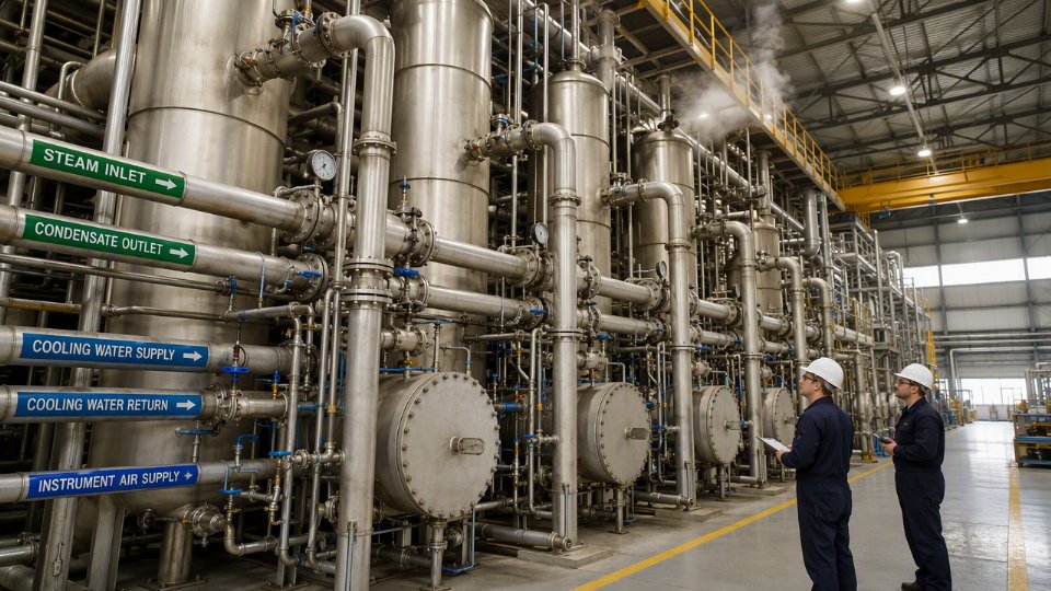
Specifying an evaporator or condenser without locking down the utility requirements first is one of the most reliable ways to commission a system that underperforms from day one. Steam supply undersized by even one pressure tier forces the heat transfer surface to work harder, cuts evaporation capacity, and pushes cycle times out — translating directly into reduced throughput and missed production targets. On the cooling side, inadequate cooling water flow or a poorly conditioned instrument air header will trigger valve hunting, unstable vacuum, and condensate flooding. The downstream cost lands on maintenance budgets and energy bills simultaneously.
Industrial evaporator and condenser systems require four core utility streams: steam (typically 1.5–10 bar[g] depending on boiling point and duty), cooling water (commonly 20–200 m³/h per MW of heat rejection), instrument air (5–7 bar[g], dew point −40°C or lower), and electrical power for drives and controls. Secondary utilities — condensate return, process water, and inert gas purge — vary by application and must be defined during P&ID development, not after equipment delivery.
What most procurement specifications get wrong is treating utilities as a site infrastructure problem rather than an equipment selection variable. The steam pressure you can actually deliver to the battery limit, not the pressure in the boiler house, determines which evaporator configuration is even viable. That distinction between available utility and assumed utility has derailed more than a few FAT sign-offs and commissioning schedules. The sections below work through each utility stream in the order a process engineer would encounter it — from the steam chest to the instrument air manifold — with realistic ranges, the variables each figure depends on, and the failure modes that follow when the numbers are treated as estimates rather than hard inputs.
Steam and Heating Medium Requirements: Pressure, Quality, and Condensate Return Specifications
The heating-side utility specification is where most evaporator procurement errors originate. Engineers reach for a standard steam pressure without back-calculating from the actual process conditions, and the result is either undersized heat transfer area or a system that floods with condensate the first week of operation.
Back-Calculating Steam Pressure from Process Conditions
Steam pressure is not a free variable. It follows directly from three stacked requirements: the process-side boiling point elevation, the minimum temperature driving force you need to sustain across the heating surface, and the additional margin consumed by fouling resistance in your LMTD calculation.
Start with the product’s boiling point at operating vacuum. Add the boiling point elevation caused by dissolved solids or viscosity — this ranges from negligible in clean water evaporation to 15–30°C in concentrated brine or sugar liquor service. Now add your minimum effective ΔT, which for most falling-film and forced-circulation designs sits between 10 and 20°C depending on tube material, surface condition, and whether you’re running a single or multiple-effect train. Layer in the fouling allowance, which erodes your clean LMTD by 5–15% depending on service, and you arrive at the required heating steam saturation temperature. That temperature maps directly to a steam supply pressure. For most food, pharmaceutical, and moderate-concentration chemical evaporators this lands in the 1.5 to 6 bar(g) range; heavy-duty chemical or desalination duties can push to 10 bar(g) or above.
Saturated vs. Superheated Steam: The Heat Transfer Penalty You Cannot Ignore
Saturated steam is the standard choice, and for good reason: condensation heat transfer coefficients on the shell side or tube side run high, the latent heat content is predictable, and control is straightforward. Superheated steam appears on site occasionally because the boiler operates at higher pressure and the steam travels a long distance before reaching the evaporator. The problem is that the superheat must be shed before condensation begins, and during that desuperheating zone the heat transfer coefficient drops sharply — often to 30–60% of the condensing value — because you are working with single-phase convection rather than film condensation. If this zone is not explicitly sized in the thermal model, the effective area is overstated. Always confirm with your equipment supplier whether the datasheet area includes a desuperheating correction when supply steam superheat exceeds roughly 10°C.
Superheated steam delivers higher heat transfer rates than saturated steam in evaporator tube bundlesFalse
Superheated steam must first desuperheat before condensation begins, producing a low-coefficient single-phase zone that reduces the effective heat transfer coefficient in that portion of the bundle compared to condensing saturated steam.
Steam Quality: Dryness Fraction, Non-Condensables, and the Water Hammer Risk
Specify a minimum dryness fraction of 0.95 at the inlet nozzle — not at the boiler outlet. Wet mains, long uninsulated runs, and poorly trapped branch lines all degrade quality in transit. Entrained condensate slugs in falling-film evaporators are particularly damaging: they cause tube vibration, accelerate corrosion at the vapor-liquid interface, and in severe cases produce audible water hammer that fatigues nozzle welds within months.
Non-condensable gases accumulate in the steam chest and blanket tube surfaces, cutting effective condensing area. Vent continuously or on a timed cycle; the vent size is a detail that disappears in early-stage datasheets and causes real efficiency loss in commissioning.
Condensate Return: Backpressure, Trap Selection, and Flooding Risk
Condensate backpressure at the trap outlet must be documented on the utility datasheet. If the condensate header runs at 0.5 bar(g) and your steam chest operates at 1.5 bar(g), you have only 1.0 bar differential across the trap — workable with a float-and-thermostatic type, which handles varying condensate loads smoothly. Thermodynamic (disc) traps work reliably in high-pressure, steady-load situations but cycle poorly under light loads and can allow condensate backup in shell-side evaporators with low steam-side ΔP.
Condensate flooding in a shell-side evaporator partially submerges the tube bundle, reduces active condensing area, and produces uneven heat flux distribution. It shows up as unexpected product concentration variance before anyone identifies the root cause.
Hot Oil and Pressurized Hot Water: When Steam Is Not the Right Answer
High-temperature applications above roughly 180°C or heat-sensitive products requiring precise temperature control often use thermal oil or pressurized hot water circuits. Thermal oil viscosity at startup — before the fluid reaches operating temperature — drives shell-side pressure drop well above design; thermal fluid systems need gradual warm-up procedures and the datasheet must specify viscosity at both minimum and maximum operating temperatures. Thermal fluid systems also require expansion tanks sized for the full volumetric expansion of the loop fluid, plus nitrogen blanketing to prevent oxidation. Pressurized hot water circuits are simpler chemically but require higher system operating pressures to maintain liquid phase, which carries its own integrity and relief valve implications.
Utility Data Required on the Evaporator Datasheet
Before a purchase order is final, the following must be locked on the datasheet: heating medium type and grade; supply pressure and temperature; return pressure and maximum allowable return temperature; maximum allowable pressure drop on the utility side (typically 0.2–0.5 bar for steam, wider for liquid media depending on pump head); fouling resistance assigned to the heating medium side; and condensate backpressure at the trap outlet. Missing any one of these forces an RFI cycle mid-fabrication or, worse, a field modification after hydrotest.
Cooling Water and Chilled Water Circuits: Flow, Temperature, Chemistry, and Fouling Control
Cooling-side utilities are where condenser designs fail in practice most often — not because the thermal calculation was wrong, but because the actual site water quality or available flow rate was never properly specified before the purchase order was placed. Getting this right requires understanding not just the temperature and flow numbers, but the chemistry that governs tube material selection and long-term fouling behavior.
Once-Through, Open Recirculating, and Closed Chilled Water: Different Problems, Different Tube Materials
Once-through systems draw from a river, coastal intake, or well. Flow is generally abundant and supply temperature is lower than cooling tower water, which benefits condenser duty. The trade-off is that the water chemistry is uncontrolled and highly variable — seasonal temperature swings, suspended solids after rain events, marine biofouling near coastal plants, and chloride levels that can fluctuate dramatically with source. Carbon steel tubes are essentially disqualified in seawater service. Admiralty brass (UNS C44300) handles moderate chloride levels well and has a long track record in utility surface condensers, but it is vulnerable to ammonia and certain process contaminants. Titanium Grade 2 is the standard choice for seawater once-through condensers above roughly 200 ppm chloride; the material cost premium is real, but the tube replacement cost if you underspec the material is far higher.
Open recirculating cooling tower systems are the most common arrangement in process plants. Supply water temperature to the condenser typically falls between 28°C and 33°C depending on ambient wet-bulb temperature and tower performance — a plant in a humid tropical climate will struggle to reach 28°C even with a well-maintained tower. Return temperature from the condenser is commonly designed to rise 5°C to 10°C, putting the return header in the 33°C to 43°C range. The heat rejection rate determines the required flow, and cooling water flow rates for surface condensers commonly fall between 20 and 200 m³/h per MW of heat rejection duty, with the wide range reflecting the allowable temperature rise and the specific condenser geometry. Because the water is recirculated and concentrated by evaporation, chloride levels, TDS, and biological fouling risk all increase over time if blowdown and chemical dosing are not actively managed. For chloride content below roughly 300 ppm with proper inhibitor programs, 316L stainless steel tubes are generally adequate. Above 300 ppm sustained chloride, duplex stainless (2205 or equivalent) or titanium should be evaluated seriously.
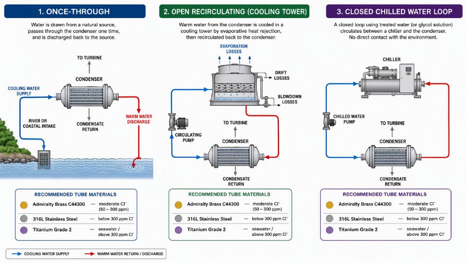
Closed chilled water loops behave differently. The fluid is treated, recirculated without concentration buildup, and controlled tightly. Supply temperature typically ranges from 7°C to 12°C, with the lower end achievable only when refrigeration system COP targets allow the compressor to run at higher pressure ratios — which increases energy cost significantly. Because fouling is minimal in a properly maintained closed loop, fouling resistance values assigned per TEMA-C class are appropriate rather than the more conservative TEMA-R values used for cooling tower water service.
Water Quality Parameters That Drive Equipment Decisions
pH should be maintained between 6.5 and 8.5. Outside this range, either acidic corrosion or scaling accelerates depending on which direction you drift. The Langelier Saturation Index (LSI) quantifies scaling tendency: a positive LSI above +0.5 indicates a water chemistry prone to calcium carbonate deposition on heat transfer surfaces, which dramatically increases fouling resistance and degrades condenser performance over a single operating season if untreated. Total dissolved solids above 1,500 mg/L warrant closer scrutiny of the inhibitor program and blowdown rate.
Biological fouling from Legionella and similar organisms is purely a health and safety concern and does not affect heat transfer performance.False
Biofilm accumulation of even 0.1 to 0.2 mm on tube surfaces can increase fouling resistance by 50% or more compared to clean tube conditions, directly raising condenser backpressure and reducing system capacity. Biological fouling control is both a safety and a process performance issue.
Consequences When Cooling Water Supply Falls Short
Inadequate cooling water flow or elevated supply temperature produces a cascade of measurable problems. In steam surface condensers, condenser backpressure rises, reducing turbine exhaust enthalpy drop and cutting power output or steam economy. In vacuum evaporator systems, the condenser is responsible for maintaining the shell-side vacuum; a degraded condenser means elevated operating pressure, higher boiling point, and reduced evaporation rate — essentially the entire evaporation duty suffers because of a utility shortfall. In refrigeration-coupled systems, the condenser backpressure translates directly to elevated compressor discharge pressure, increasing shaft power demand and risking high-pressure cutout trips.
Pressure Drop Limits and Tube-Side Design Consequences
Cooling water systems typically impose a maximum allowable pressure drop on the tube side of 0.5 to 1.5 bar, depending on pump head availability and piping losses to and from the condenser. This constraint directly influences tube-side pass arrangement: more passes improve the log mean temperature difference and can reduce surface area, but each additional pass adds pressure drop. Tube diameter selection — commonly 19 mm to 25 mm OD for cooling water service — and baffle cut in the shell affect shell-side flow distribution and vibration risk, but the tube-side pass count is often the first design variable that hits the pressure drop ceiling. Specify the available cooling water differential pressure at the equipment nozzles early in the datasheet, not after the vendor has already fixed the tube layout.
Electrical Power Utilities: Drives, Instrumentation, Heat Tracing, and Area Classification
Electrical power is consistently the most underspecified utility in early-stage evaporator and condenser inquiries. By the time a vendor returns a motor list and a heat tracing schedule, the site electrical engineer has often already sized the substation and laid out cable trays. Retrofitting that design for an unaccounted 75 kW vacuum pump or a heat-traced product line adds cost that procurement never budgeted for.
Electrically Driven Components and How to Build the Load List
An evaporator-condenser system carries more rotating and resistance loads than most procurement teams initially estimate. Feed pumps, product pumps, and condensate extraction pumps are obvious. Less obvious — but frequently significant — are the mechanical vacuum pump or liquid-ring vacuum pump serving the vapor body, cooling tower fan motors or air-cooled condenser fans where forced-draft units are used, and agitator drives in forced-circulation evaporators. A falling-film evaporator on a sugar or dairy application may run a relatively small agitator, but a forced-circulation crystallizer for an ammonium sulfate or sodium sulfate duty can carry agitator motors in the 30 to 200 kW range depending on liquor viscosity, vessel diameter, and circulation velocity.
Build the motor list from the equipment datasheets, not from process flow diagrams. Vendor datasheets will state absorbed power at design duty; installed connected load should carry 10 to 20% above the sum of calculated absorbed powers, but what that margin actually needs to be depends on whether motors are running simultaneously at peak load or staggered during startup sequences. Communicate this figure explicitly to the site electrical engineer — don’t assume they will apply their own margin on top of yours.
Voltage, Frequency, and Motor Starting Method
Globally, the two dominant supply standards are 380/400 V at 50 Hz and 460 V at 60 Hz, though 6.6 kV and 11 kV medium-voltage supplies appear once individual motors exceed roughly 200 to 250 kW. Confirm the site standard before the motor datasheet is issued; a motor wound for 460 V 60 Hz cannot simply be re-terminated for 400 V 50 Hz without a torque and thermal re-evaluation.
Starting method has real consequences for cable sizing and switchgear ratings. Direct-on-line starting draws six to eight times full-load current for several seconds. Star-delta reduces the starting current but produces a torque dip at the transition that can trip a pump handling high-viscosity product. Soft starters and variable frequency drives (VFDs) limit inrush more effectively and give precise speed control on cooling tower fans and feed pumps — particularly valuable where evaporation rate must be modulated without throttling valves. VFDs also introduce harmonic distortion into the supply, so the site electrical engineer needs the drive specifications to assess whether harmonic filters are required.
Electrical Area Classification: ATEX and NEC Requirements
Where evaporators handle solvents, alcohols, hydrocarbons, or any flammable vapor, the vapor body and surrounding piping fall under hazardous area classification. ATEX Zone 1 or NEC Class I Division 1 environments require motors with EExd (flameproof) or EExe (increased safety) enclosures; standard TEFC motors are not acceptable regardless of what a low-cost quotation may offer. Control panels must carry appropriate IP ratings — IP54 as a bare minimum in most plant environments, IP65 or higher in washdown or corrosive atmospheres. Standard junction boxes and terminal enclosures near solvent evaporation zones are a compliance violation and an ignition risk.
A standard TEFC motor is acceptable in an ATEX Zone 1 area if it carries an IP55 rating.False
IP rating addresses ingress protection only. ATEX Zone 1 requires certification to explosive atmosphere standards (EExd or EExe), which involves ignition risk assessment, surface temperature classification, and third-party certification — none of which an IP55 rating provides.
Electric Heat Tracing on Piping and Instrument Lines
Viscous products, low-ambient installations, and steam-traced lines that cross into electrical area classification zones all create demand for electric heat tracing. The choice between self-regulating trace cable and constant-wattage trace cable is not arbitrary. Self-regulating cable adjusts its output as ambient temperature changes and cannot overheat itself — appropriate for product lines where temperature must be maintained within a relatively narrow band. Constant-wattage cable delivers a fixed heat flux regardless of temperature, which suits freeze protection on instrument impulse lines and drain legs where the concern is a hard lower limit rather than a precise setpoint. Instrument impulse lines on evaporator vapor bodies are a frequent oversight: if a pressure transmitter impulse line freezes in a cold climate or an outdoor installation, the SIS loses its pressure signal.
UPS and Emergency Power for Safety Instrumented Systems
High-level shutdown valves on evaporator vapor bodies, pressure relief monitoring, and emergency isolation on condensate systems are typically part of the safety instrumented system. These elements need uninterruptible power — sized for at least 30 to 60 minutes of autonomous operation depending on the site emergency response plan. UPS capacity must appear in the electrical load list from the earliest engineering phase; it is a small line item in kVA terms but a critical one. Losing SIS power during a utility outage because the UPS was undersized or omitted is the kind of failure that produces a regulatory incident report rather than just a production loss.
Instrument Air and Inert Gas Utilities: Purity, Pressure, and Dew Point Requirements
Instrument air and nitrogen are easy to treat as background utilities — they show up late in the design process, get assigned to a standard site header, and rarely receive the same scrutiny as steam or cooling water. That habit creates real problems during commissioning. Pneumatic positioner failures, solenoid valve sticking, and oxygen ingress into product receivers are disproportionately traced back to utility quality that was never formally specified.
Instrument Air: Why the Quality Limits Exist
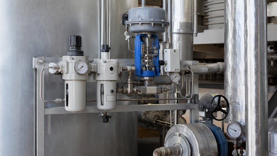
The baseline standard referenced across most industrial sites is ISA-7.0.01, with ISO 8573-1 providing the internationally recognized purity class framework. Both converge on the same working requirements: supply pressure held at 5.5 to 7 bar(g) at the instrument header (not at the compressor discharge — the distinction matters when headers are long or poorly sized), a pressure dew point of -40°C or lower at line pressure, oil carryover below 0.01 mg/m³, and particulates filtered to below 1 micron.
Each of those limits protects a specific failure mode. The dew point requirement exists because condensed water inside a pneumatic positioner’s pilot circuit causes corrosion of the feedback spring and seats, leading to drift or complete loss of valve response. Oil carryover coats the internals of solenoid valves and pilot relays, causing sluggish actuation — a minor nuisance on a modulating control valve, but a critical failure on an ESD valve that must stroke to closed within a specified time. Particulates above 1 micron score restriction orifices in positioners and restrict the nozzle-flapper assembly in older pneumatic controllers still common in retrofit plants.
Calculating Instrument Air Demand for Evaporator and Condenser Systems
Demand calculation is not simply a headcount of control valves. The actuator cylinder volume for each valve must be totalled, then multiplied by the required number of strokes per hour under normal operation, then a surge factor added for simultaneous ESD actuation. On a multi-effect evaporator train, the feed control valve, each effect’s vapor outlet valve, the condensate drain valve, and the final product discharge valve all belong to the demand calculation. ESD valves are the critical case: if the site safety requirement calls for full stroke in 3 to 5 seconds, the air receiver sizing must support that stroke without allowing header pressure to drop below the minimum operating pressure of the positioner — typically 3.5 bar(g). Undersizing the receiver by even 20% means the last valve in a simultaneous ESD sequence strokes slowly or incompletely.
Instrument air dew point at line pressure of -40°C or lower is sufficient to prevent condensation inside pneumatic positioners in all standard industrial ambient conditions.True
At -40°C pressure dew point, moisture will not condense inside instrument tubing or positioner internals under any realistic plant ambient temperature, including arctic outdoor installations, making this the accepted industry threshold per ISA-7.0.01.
Nitrogen Utility: Blanketing, Purging, and Pressure Testing
Nitrogen requirements split across three distinct duties, each with a different purity grade and supply logic. General vessel blanketing on product receivers — preventing atmospheric oxygen or moisture from contacting the evaporated product — is adequately served by 99.5% purity nitrogen. This grade is practical from onsite pressure swing adsorption (PSA) generators for sites with continuous demand above roughly 50 to 200 Nm³/h, depending on unit capital cost versus delivered cylinder cost at your location.
Pharmaceutical and food-grade evaporator systems require 99.99% purity or higher for any vapor space that contacts the product stream. At that purity level, PSA generation requires additional polishing beds, and many smaller sites find liquid nitrogen vaporization more cost-effective and auditable for regulatory purposes. Cylinder banks remain practical only for intermittent maintenance purging or pressure testing duties — the flow rates required for continuous blanketing make cylinders expensive and logistically burdensome.
Purging of vapor spaces before maintenance entry is a separate procedural requirement. The nitrogen flow rate and duration must be calculated from the vessel volume and the target oxygen concentration (typically below 1% by volume before confined space entry protocols are modified), not simply assumed to be adequate after a fixed time interval.
Pressure testing of completed assemblies presents a specific coordination requirement. When the process fluid is flammable or toxic, hydrostatic testing with water may be acceptable for the pressure boundary, but pneumatic leak testing of the assembled piping and instrumentation — performed at lower pressure, typically 1.05 to 1.1 times the design pressure — must use nitrogen, not instrument air, to eliminate any ignition risk from residual process vapors. The test pressure must be documented in the FAT package and verified against the mechanical design pressure of every connected component.
The Blanketing Pressure and Relief Valve Interaction
The nitrogen blanketing pressure on a product receiver or evaporator vapor body must be set below the relief valve set point with adequate margin — typically the blanketing regulator is set at 0.05 to 0.2 bar(g) above atmospheric, while the relief device may be set at 0.5 to 1.5 bar(g) depending on vessel design. If a blanketing regulator fails open, nitrogen flow can pressurize the vessel toward its relief set point. Process and mechanical engineers must coordinate this during hazard review: the blanketing supply pressure available at the header must be confirmed against the maximum credible failure scenario, and the relief device capacity must account for nitrogen inflow as a credible overpressure source.
Header Separation and Cross-Contamination Prevention
Instrument air and nitrogen headers must be physically separated throughout the plant, not just at the utility skid. Both headers require permanent, color-coded labeling at intervals that meet local piping identification standards, and every interconnection point — including any temporary connection used during pressure testing — must be equipped with a check valve (non-return valve) to prevent backflow from one system to the other. This is not a theoretical concern. Nitrogen contamination of an instrument air header starves the air compressor controls of signal; instrument air contamination of a nitrogen blanketing header introduces moisture and potential oxygen, defeating the blanketing function entirely.
During P&ID review in the factory acceptance test (FAT) document check, the reviewer should specifically verify that the instrument air supply tie-in and the nitrogen blanketing tie-in are shown on separate headers, that check valves are called out on the P&ID rather than left to field judgment, and that the blanketing pressure regulator set point is documented and traceable to the vessel mechanical design datasheet. These details are frequently missing from vendor-supplied P&IDs and must be caught before the drawing is approved for construction.
Vacuum System Utilities: Ejectors, Liquid Ring Pumps, and Their Steam or Water Demands
Many industrial evaporators run below atmospheric pressure by design, not by coincidence. Reducing the boiling point through vacuum lets you evaporate heat-sensitive products — fruit juice concentrates, API intermediates, specialty polymer solutions — at temperatures that would otherwise cause degradation, color change, or loss of activity. It also makes low-grade steam or hot condensate viable as a heating medium, squeezing value out of energy that would otherwise go to the cooling tower. And it widens the temperature driving force across the heating surface without forcing you to higher steam pressures, which carries its own capital and safety costs. The vacuum level is therefore a process decision with direct utility consequences that flow right back into the steam, cooling water, and electrical budgets.
Steam Jet Ejectors: Motive Steam Demand and Its Dependencies
A steam jet ejector is mechanically simple — no moving parts, low maintenance — but it is a significant steam consumer. Motive steam pressure typically runs between 5 and 12 bar(g), with the exact figure set by the required suction pressure, the molecular weight of the vapor being handled, and the number of stages. A single-stage ejector pulling a moderate vacuum and handling roughly 10 kg/h of air-equivalent non-condensable load will consume somewhere between 80 and 150 kg/h of motive steam. That range depends heavily on the steam quality: wet or contaminated steam erodes nozzles and shifts the operating curve within months. Specify dry saturated steam with a minimum superheat of 10 K at the ejector inlet, and include a separator on the motive steam line as a hard requirement.
Multi-stage ejector trains — two or three stages with inter-condensers between them — are used when the target vacuum falls below about 30 mbar(a). Each inter-condenser knocks out condensable vapors before they reach the next stage, dramatically cutting the vapor load and therefore the motive steam consumption of downstream stages. This is where cooling water supply temperature becomes a governing constraint. If your cooling water arrives at 32°C instead of the design 28°C during summer peak, the inter-condenser cannot condense as efficiently, the vapor load on the second-stage ejector rises, and achievable vacuum degrades — sometimes by 5 to 15 mbar(a), which can be enough to shift your product boiling point outside the acceptable process window.
Liquid Ring Pumps and Hybrid Systems: Seal Water Requirements
Liquid ring vacuum pumps reach operating vacuums down to around 30 to 50 mbar(a) in single-stage configuration, consuming seal water — or recovered process condensate — at temperatures between 15 and 40°C. A rough utility benchmark: expect seal water flow of 0.5 to 2 m³/h per kilowatt of shaft power, with the lower end applying when the seal liquid is circulated through a small heat exchanger rather than run once-through to drain. Seal water temperature is the dominant variable controlling the minimum achievable suction pressure; warm seal liquid raises vapor pressure inside the ring and sets a hard floor on vacuum. Running seal water above 40°C in a pump rated for deeper vacuum is a common site error that generates nuisance alarms and erodes production rates without an obvious cause.
For duties below 5 mbar(a) — thin-film evaporation of pharmaceutical solvents, for example — a hybrid ejector/liquid ring system is the practical solution. The ejector handles the coarsest compression stage using motive steam, while the liquid ring pump takes the discharge and compresses to atmosphere. This splits the utility load: motive steam consumption drops compared to an all-ejector train, and the liquid ring pump operates at a more manageable suction pressure where its efficiency is reasonable.
Utility Tie-In Requirements and Condensate Drain Geometry
Every vacuum system needs a defined set of utility connections that must appear on the P&ID before detailed engineering can proceed. The motive steam line requires an isolation valve, a pressure control valve with set-point documentation, and a drip leg. The seal water circuit needs a supply isolation valve, a flow indicator, and a drain routed to a collection system — not to an open floor drain, given that seal water in solvent service is contaminated. Cooling water connections to the inter-condenser and after-condenser require inlet temperature monitoring, because as discussed, that temperature governs the achievable vacuum. Non-condensable vents must route either to atmosphere (if the vapor is inert and non-hazardous) or to a thermal oxidizer or scrubber for solvent-laden streams.
Condensate drain legs deserve special attention. The barometric leg height must be calculated from the vacuum depression: for a system operating at 100 mbar(a), the liquid column must stand at least 9.3 meters to prevent backflow. Many plants install condensate pump-out systems instead of barometric legs where headroom is limited, but those pumps need to be sized for the condensate load at peak evaporation rate, and their seal material must be compatible with the condensate composition.
A liquid ring vacuum pump can achieve vacuum levels below 1 mbar(a) in single-stage operation with standard water-ring seal fluid.False
Single-stage liquid ring pumps are practically limited to around 30–50 mbar(a) when using water as the seal liquid, because the vapor pressure of water at operating temperature sets a hard floor on suction pressure. Achieving pressures below 5 mbar(a) requires either a two-stage liquid ring arrangement, a hybrid ejector/liquid ring train, or the use of a lower-vapor-pressure seal liquid such as a glycol solution.
FAT Inspection Points for Vacuum System Components
Factory acceptance testing of vacuum system components is frequently underspecified in purchase orders. At minimum, the complete assembled vapor path — from evaporator vapor outlet through inter-condensers to ejector or pump discharge — should be leak-tested at the design vacuum level, holding for a minimum period agreed in the inspection test plan, typically 30 to 60 minutes. Any pressure rise rate above a defined limit indicates a leak that will cost you vacuum performance and potentially product contamination in service. The motive steam pressure regulator set point should be verified against the design value with the ejector running under load, not just bench-set. Condensate drain leg dimensions — specifically the vertical drop from the inter-condenser hotwell to the condensate collection point — should be physically measured and compared against the calculated minimum based on the design vacuum depression. These are millimetric details that rarely appear on a vendor’s standard ITP unless the buyer puts them there.
Factory Acceptance Test (FAT) Utility Verification: Dimensional Checks, NDE, Pressure Testing, and Release Procedures
FAT is where utility specifications stop being numbers on a datasheet and become physical reality you can measure, mark up, and sign off — or reject. For evaporator and condenser systems, the utility connections are the most failure-prone handoff between manufacturer and site. Getting this verification right before a vessel leaves the shop floor is substantially cheaper than correcting it after it is bolted into a structure forty feet off grade.
Dimensional Inspection of Utility Nozzles
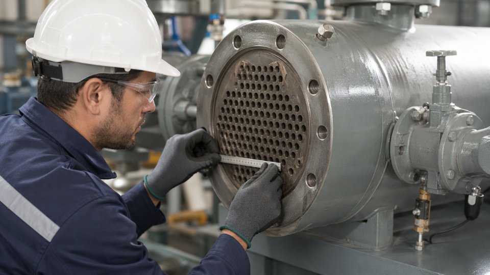
Start with the certified general arrangement (GA) drawing, revision-controlled and stamped. Every utility nozzle — steam inlet, condensate outlet, cooling water in and out, instrument air branch, vacuum connection — needs to be checked against that drawing for angular orientation (typically tolerance ±1° on a protractor check against a plumb line), projection from the shell centerline, and flange face finish. For raised-face flanges serving steam or cooling water service, the serration finish should be 125 to 250 AARH; a smooth or torn face will cause gasket blow-out at startup.
Check nozzle bore and wall schedule against the applicable piping class. A nozzle called up as 3-inch Schedule 80 that was fabricated from Schedule 40 stock is not a minor paperwork issue — it changes the pressure rating and the weld joint geometry. Also verify that every reinforcement pad carries an open tell-tale hole, typically a 6 mm tapped hole at the lowest point of the pad. If it is plugged with weld spatter or primer, the pad cannot be leak-tested during commissioning and a corrosion cavity can develop undetected underneath.
NDE Scope on Utility-Side Welds
For shell-and-tube equipment under ASME Section VIII Division 1, the NDE scope on utility-side welds follows UW-11. Shell longitudinal and circumferential seams on the shell side (which typically carries the heating steam or cooling water) require RT or UT depending on joint efficiency claimed in the design calculation. If the manufacturer claimed a joint efficiency of 1.0, full RT or UT is mandatory — spot radiography is not acceptable and the inspector should verify this against the Manufacturer’s Data Report (Form U-1).
Nozzle fillet welds get MT or PT. MT is faster and more sensitive to near-surface linear defects in carbon steel; PT is the fallback when the geometry or material makes magnetization impractical. When P-number 3, 4, or 5 materials are present — Cr-Mo alloys show up in high-pressure steam service evaporators — hardness testing of weld heat-affected zones is required to confirm post-weld heat treatment was effective. Acceptable hardness ranges depend on material grade, but for 2.25Cr-1Mo (P-5B), HAZ hardness above approximately 235 HBW is a rejection criterion under most client specifications and indicates PWHT was either skipped or inadequate.
Spot radiography at a 10% sampling rate provides the same structural assurance as 100% RT for pressure vessel seams.False
Spot RT per ASME UW-11(a)(5) only permits a reduced joint efficiency (typically 0.85 versus 1.0). It does not confirm every weld is sound. Fitness-for-service is probabilistic, not equivalent.
Pressure Test Procedures for Utility Circuits
Hydrostatic test pressure on the shell side is 1.3 times the maximum allowable working pressure (MAWP), adjusted for the ratio of allowable stress at test temperature to allowable stress at design temperature — not simply 1.3 × design pressure, and that distinction matters when operating temperature is elevated. Gauges must carry current calibration certificates traceable to a national metrology institute; expired calibration is a stop-work item, not a note-for-later.
Minimum hold time before the inspector can sign off is 30 minutes for hydrostatic testing. During that hold, walk every utility nozzle, every flange, and every instrument connection. Any visible weeping is a rejection.
When the tube side cannot be hydrostatically tested — common when residual water would contaminate a product sensitive to moisture, such as in falling-film evaporators handling hygroscopic materials — a pneumatic leak test at 1.1 times design pressure is used instead. The risk profile is different. Pneumatic testing stores significantly more energy than hydrostatic testing at the same pressure, so personnel must be clear of the test zone and the pressure must be raised in increments, typically to 50% of test pressure first, held briefly, then stepped up. The hold time is a minimum of 10 minutes before sign-off, though most client specifications extend this to 20–30 minutes.
Coating and Surface Protection Inspection
Surface preparation on external carbon steel shells should meet Sa 2.5 per ISO 8501-1 (or the SSPC-SP 10 near-white blast equivalent) before any primer is applied. Check this with a surface profile gauge — a replica tape reading typically between 40 and 70 microns Rz for most industrial coating systems. DFT measurements using a calibrated magnetic gauge should be taken at a minimum of five points per square meter on representative surfaces; results below the minimum specified DFT are cause for remedial coating before release.
Internal linings in cooling water channel covers and tube sheets need holiday testing. For thin organic linings (below approximately 500 microns DFT), a low-voltage wet sponge tester at 67.5 V DC is the standard method. For thicker linings or glass-flake epoxy systems, a high-voltage spark tester set to approximately 100 V per micron of lining thickness is used. A single holiday in a cooling water channel lining on a seawater-cooled condenser can initiate a crevice corrosion pit that perforates a tube sheet in under two years of service.
Utility nozzle bores in cooling water service must be coated or protected per the corrosion protection specification — it is surprisingly common for fabricators to leave bare metal inside nozzles that were added late in the fabrication sequence.
FAT Document Review and Punch List
Before any pressure test witness signature goes on record, the document review must be complete. That means material test reports (MTRs) for utility nozzle flanges, tube sheets, and any utility piping stub-ends; a weld map that ties each NDE record to a specific weld number on the drawing; calibration certificates for all test gauges and NDE instruments used during the FAT; and the pressure test record form with inspector, date, ambient temperature, and test medium noted.
The punch list — sometimes called a deficiency list — should categorize each open item as Category A (must be resolved before shipping release) or Category B (can be resolved at site before commissioning). A missing tell-tale hole test is Category A. A minor touch-up on external primer is typically Category B, with photographic evidence required.
Shipping Release Procedure
The final walk-down before an Inspection Release Note (IRN) or Mill Release Certificate is issued confirms that every utility nozzle is blinded with a temporary steel blind or bolted flange cover, not plastic wrap. The shell side should be either nitrogen-purged to a slight positive pressure (typically 0.3 to 0.5 bar(g) of dry nitrogen) or loaded with desiccant bags, with the quantity documented. Both the purge pressure and desiccant placement are recorded photographically along with the nameplate and nozzle orientation photos.
The IRN is not a formality. It is the document that legally transfers responsibility for the equipment’s conformance from the manufacturer to the logistics chain. Issue it only when every Category A punch list item is closed and witnessed.
Utility Balance Table: How to Document and Present All Utility Requirements for EPC Procurement
A utility balance table is not a summary document you assemble at the end of basic engineering — it is a live working document you start building the moment equipment selection begins. Its purpose is to consolidate every utility demand from every piece of equipment into one structured matrix, giving the site utility engineer a single source of truth for sizing steam headers, cooling water mains, pressure reduction stations, instrument air receivers, and condensate collection systems. On EPC projects where evaporator trains and condenser banks are procured in parallel with civil and piping design, a missing or outdated utility balance is one of the fastest ways to create costly rework when a 10-inch cooling water header turns out to be 30% undersized at tie-in.
What the Table Must Contain
For evaporator and condenser systems specifically, every row in the utility balance table should represent one utility stream on one equipment item, and every column should carry enough information that an engineer who has never visited the site can size a pipe or select a control valve without asking a single clarifying question. The minimum column set is: equipment tag number, utility type, supply condition (pressure in bar(g), temperature in °C, and phase), return condition (same parameters), normal flow rate, maximum flow rate, minimum flow rate, connection size and ANSI/PN rating, P&ID tie-in tag, and a remarks column for intermittent versus continuous service flags. Omitting the P&ID tie-in tag is particularly common on early-stage tables and forces a reconciliation exercise later that can take a junior engineer two to three days to complete under pressure.
Calculating Site-Level Totals Correctly
Summing individual equipment demands gives you the installed load, not the design load for the header. For cooling water serving multiple condensers, apply a simultaneity factor — typically 0.7 to 0.9, depending on whether the condensers operate on independent product streams or share feed from a common evaporator train. A system where three condensers can all hit peak duty at the same moment warrants a factor closer to 1.0; a multi-effect evaporator where only one effect condenses at maximum rate at any given time justifies a lower factor, but you must document the operating logic that supports your choice or a future auditor will challenge it.
After applying the simultaneity factor, add a contingency allowance of 10 to 15% for future capacity expansion. What that percentage actually covers depends on site master plan assumptions, so state them explicitly in the table footer rather than embedding a silent contingency that nobody can trace in three years when the plant wants to add a fourth evaporator effect.
A simultaneity factor below 0.7 is rarely defensible for cooling water systems serving condensers on a single continuous process train, even when flows are staggered.True
Condensers on a single process train typically respond to the same upstream feed upsets simultaneously, meaning their peak demands tend to coincide rather than offset each other.
Linking the Utility Balance to the Heat and Material Balance
The utility balance is a derivative document — it lives downstream of the heat and material balance (HMB). When feed temperature drops by 10°C or product concentration target increases, steam consumption rises and cooling water demand shifts. Those changes must propagate into the utility balance under the same revision number and issue date as the revised HMB. Revision control discipline is not bureaucratic overhead here; it is the mechanism that prevents a procurement engineer from ordering a steam trap manifold sized to a superseded flow rate.
On practical EPC projects, assign one engineer ownership of both documents and require co-signature on any revision that changes a utility flow rate by more than 5% of the previous issued value. That threshold is arbitrary but defensible — below it, the change is typically within instrument measurement uncertainty anyway.
Structuring RFQ Packages for Vendors
When issuing RFQs to evaporator or condenser vendors, specify utility conditions at the battery limit of the equipment skid, not at the plant utility header. The difference matters because pressure drop through the site piping, elevation changes, and control valve pressure drop are all site-specific — the vendor cannot know them and should not be expected to guess. State: steam available at the skid inlet flange at X bar(g) saturated, cooling water available at Y°C with a maximum allowable return temperature of Z°C, instrument air at 6 bar(g) minimum with a -40°C dew point. Then require the vendor to confirm actual consumption figures — not “as specified” checkmarks — in their technical proposal. Those confirmed figures are what you enter into the utility balance during bid evaluation, and any discrepancy between the vendor’s number and your estimate is a flag that either your process design or their thermal rating needs scrutiny.
Errors That Cause Real Project Problems
Three omissions appear repeatedly in utility balance documents and all of them create problems after mechanical completion. First, steam trap condensate loads are routinely left out of the condensate return balance. A single falling-film evaporator heating section can generate 0.3 to 1.5 t/h of condensate depending on steam pressure and duty, and if the condensate return header and flash vessel were sized without that load, you will have a capacity problem on day one of commissioning. Second, the utility consumption of steam ejectors and liquid ring vacuum pumps is frequently missing. Ejectors consume motive steam continuously — sometimes at rates comparable to the process heating steam itself — and that load belongs in the steam balance. Third, startup, shutdown, and emergency depressurization scenarios are almost never included in early utility balance revisions. Startup steam demand for warming an evaporator train can be two to three times the normal operating rate for a period of 30 to 90 minutes depending on equipment mass and insulation quality. Size your pressure reduction station for that peak, not for steady-state flow, or your operators will spend their first startup fighting low steam pressure.
Frequently Asked Questions About Utilities for Industrial Evaporator and Condenser Systems
What is the minimum cooling water supply temperature that allows a surface condenser to achieve full vacuum?
The achievable vacuum is a thermodynamic ceiling, not a design choice. Your condenser can only condense vapor down to the saturation temperature that corresponds to the cooling water inlet temperature plus the minimum approach temperature — typically 3 to 5°C for well-designed surface condensers with adequate tube area. Feed in cooling water at 30°C and the condensate exits at roughly 33 to 35°C, which corresponds to a steam saturation pressure of approximately 50 to 56 mbar(a). That is the vacuum floor for that utility condition.
Sites running heat-sensitive evaporation — pharmaceutical concentrates, enzyme broths, fruit juice — often cannot tolerate process temperatures above 45 to 50°C. They require chilled water at 7 to 12°C to push the condenser vacuum below 20 mbar(a). If your site utility header delivers cooling tower water at 32°C in summer, that constraint must be embedded in the evaporator datasheet before the vendor sizes the heating area. Discovering the mismatch after fabrication is expensive.
Can the evaporator system operate safely if instrument air pressure drops below minimum?
Short answer: it will shut down in an orderly way, not fail catastrophically — if the system was engineered correctly. Most control valves on evaporator and condenser service are specified fail-open or fail-closed in the cause-and-effect matrix based on process safety logic. On loss of instrument air, they move to that defined safe position. What prevents an abrupt, uncontrolled shutdown is the local instrument air receiver, which should be sized for a minimum of 15 minutes of autonomous supply at normal consumption. That window allows the distributed control system to execute a sequential, safe process trip rather than a hard crash that can thermally stress equipment or leave vessels at uncontrolled pressure.
A local instrument air receiver sized for 15 minutes of autonomy is sufficient for an orderly evaporator shutdown on loss of plant air supply.True
This is standard engineering practice consistent with ISA and IEC 61511 functional safety guidance; the 15-minute window allows sequential valve positioning and operator confirmation before pressure and level conditions reach unsafe limits.
If your site air system has a history of pressure dips during high-demand periods — compressor changeover, winter cold starts — add a high-priority branch with a check valve and dedicated receiver for the evaporator and condenser control loops. It is a small investment against an unplanned batch loss.
How should we specify cooling water fouling resistance for a condenser in a hard-water region?
Start with TEMA Table RGP-T-2.4. The standard fouling resistance for recirculating cooling water on the tube side is 0.000176 m²·K/W (0.001 h·ft²·°F/BTU) for TEMA R class equipment. That figure assumes a reasonably managed cooling tower system. Sites where the make-up water hardness exceeds 300 mg/L as CaCO₃, or where silica runs above 150 mg/L, should apply a multiplier of 1.5 to 2.0 on the TEMA default and budget the additional surface area into the condenser specification from day one. Antiscalant dosing programs can control the deposition rate, but they require consistent chemical management and blowdown control — document the actual treatment program and hold the vendor to a fouling factor that matches your real site water chemistry, not the TEMA baseline.
What utility connections are required during FAT pressure testing at the manufacturer’s shop?
The manufacturer supplies the temporary hydrostatic test circuit — test pump, manifold, isolation valves, and fill connections. Your inspector’s job is to verify three things before the pressure ramp begins: the test pump gauge and reference gauge both carry current calibration certificates, the test water temperature is confirmed above the nil-ductility transition temperature of the shell material (typically above 15°C for carbon steel), and a pressure relief device set at no more than 1.05 times the specified test pressure is installed on the circuit. Over-pressurization during shop testing has caused shell deformation that is difficult to detect visually but can compromise long-term fatigue life.
Is nitrogen blanketing always required for evaporator product receivers?
Not universally, but the HAZOP is the only document that gives a project-specific answer. Nitrogen blanketing is required when the product degrades on contact with oxygen — pharmaceutical intermediates, edible oils, certain fine chemicals — or when the vapor space could accumulate flammable vapors above the lower explosive limit. Vessels operating under vacuum also need positive inert blanketing to prevent air ingress on shutdown or pressure transients. For non-volatile, non-flammable aqueous streams such as inorganic salt solutions or plain water evaporation, nitrogen blanketing is typically unnecessary and adds capital and operating cost without safety benefit. Write the HAZOP action item clearly and get it closed before finalizing the vessel specification.
How does steam pressure variation on the utility header affect evaporator capacity?
Heat duty equals U × A × LMTD. Steam supply pressure directly sets the saturation temperature of the heating medium, which sets the hot-side temperature in the LMTD calculation. A drop in steam supply pressure reduces that saturation temperature, compresses the temperature driving force, and cuts capacity. A 10% reduction in absolute steam pressure typically reduces LMTD by 3 to 8°C depending on the boiling point elevation of the process fluid — a product with high dissolved solids runs closer to the heating medium temperature and suffers proportionally more. The practical consequence is a 5 to 15% reduction in evaporation rate, which ripples directly into product throughput and downstream drying or crystallization schedules.
The guarantee to request from your utility engineering team is a minimum steam pressure at the battery limit under worst-case simultaneous demand — not the normal operating header pressure. Size the evaporator heating surface on that worst-case figure. The difference between guaranteed minimum and normal operating pressure is free capacity margin, not wasted metal.