
The allowable pressure drop of a shell-and-tube heat exchanger should come from the hydraulic limitations of the surrounding process or utility system—not from a universal value copied into the equipment datasheet.
EPC buyers should determine the pressure difference or head available at the required flow, account for other system losses and operating margins, and allocate a defensible pressure-drop limit to each side of the exchanger. Suppliers should then demonstrate that their proposed complete exchanger meets the required thermal duty within those limits across the agreed operating cases.
A lower predicted pressure drop is not automatically a better equipment proposal. It may increase heat-transfer area or equipment cost, and in a shared distribution network it may change how flow is balanced. The procurement objective is to find a technically viable arrangement with an acceptable overall system cost and operating performance.
Why Is There No Universal Allowable Pressure Drop?
An allowable exchanger pressure drop is a project-specific hydraulic constraint.
The same shell-and-tube exchanger duty may be served by a dedicated pumped loop, a shared cooling-water header, a pressure-driven process stream or a low-pressure gas system. Each arrangement has different limits on how much pressure can be lost while maintaining the intended process conditions.
A pressure loss that is manageable in one system may be unacceptable in another.
Start With the System, Not a Generic Number
Before assigning a maximum pressure drop to an exchanger, the responsible process or hydraulic engineer should identify:
- The available driving pressure or hydraulic head.
- The required flow at the relevant operating conditions.
- The pressure needed at downstream equipment or users.
- Losses through other elements of the hydraulic path.
- Applicable operating, control and design margins.
- The range of credible system operating cases.
For pumped liquid systems, the operating point depends on the interaction between the pump performance curve and the system resistance curve. The Hydraulic Institute’s pump and system curve guidance explains why a pump’s rated flow or nameplate head cannot independently establish the flow available after the exchanger is installed.
For shared cooling-water systems, the pressure difference between the supply and return headers and the balancing of parallel consumers are particularly important.
The IOGP JIP33 S-614 supplementary specification for shell-and-tube heat exchangers, Appendix D.3.5, discusses allowable pressure drop in relation to the exchanger process datasheet, fouled conditions and distribution-system hydraulics. It is an industry procurement reference for projects that adopt it, not a universally applicable regulation.
Separate the Two Fluid Circuits
A shell-and-tube exchanger contains two process streams that may belong to different hydraulic systems.
The shell-side allowable pressure drop and tube-side allowable pressure drop must therefore be established separately.
For example, one side may be connected to an existing cooling-water distribution system while the other side is driven by a dedicated process pump. The available differential pressure, fluid properties and operating restrictions will differ.
Unused allowance on one side cannot automatically be transferred to the other.
The general factors that cause pressure loss in an exchanger are covered in the site’s heat exchanger technical parameters guide. The present article focuses instead on how much pressure loss the system can allocate and how competing complete-equipment designs should be assessed.
How Is the Exchanger Pressure-Drop Budget Derived?
The exchanger allowance should be derived from a hydraulic balance over a clearly defined part of the system.
For an applicable single-phase liquid flow path, a simplified pressure-difference budget can be expressed as:
Available pressure difference = Other allocated system losses + Exchanger pressure-drop allowance + Required margin
The components must refer to the same operating case and compatible hydraulic boundaries. Pumping head, static elevation effects and pressure differences should not be combined without using the appropriate hydraulic formulation.
Define the Hydraulic Boundary
For a dedicated pumped loop, the analysis may begin with the required system flow and the pump’s available differential head at that operating point.
The engineer should account for the relevant static head or pressure requirements and flow-dependent losses elsewhere in the system.
For an exchanger connected between common utility headers, the relevant starting point may instead be the differential pressure available at the supply and return connections.
The buyer should establish whether the quoted available differential already accounts for upstream distribution piping and whether branch losses or required control-valve authority remain to be allocated.
A system loss must not be deducted twice.
Illustrative Allocation of a 90 kPa Budget
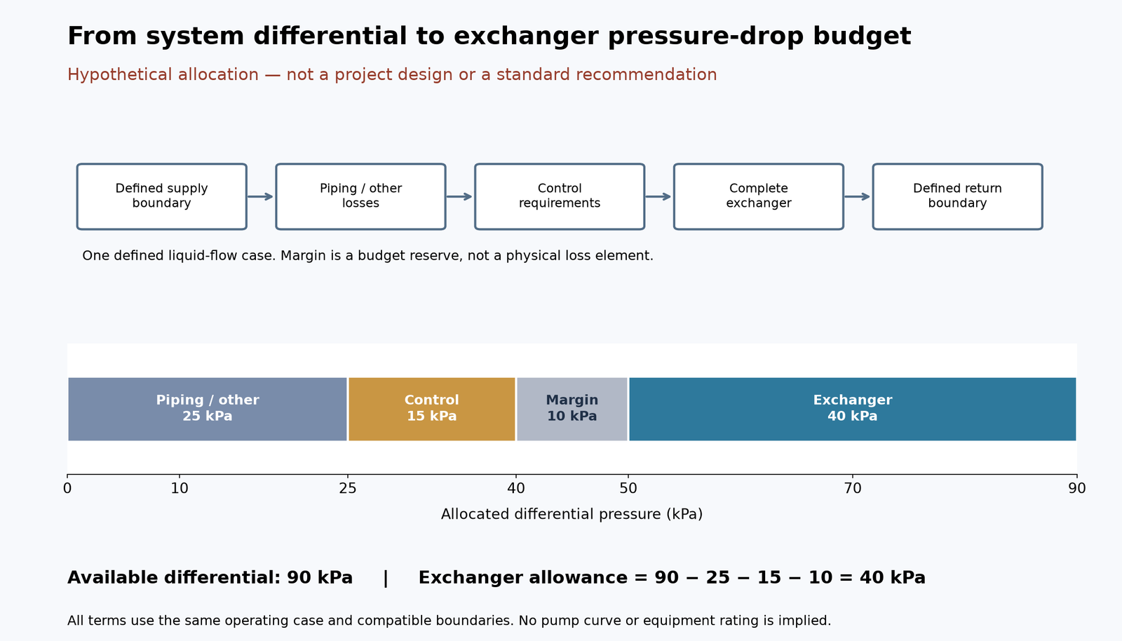
Consider a hypothetical liquid branch in which engineering has established an available pressure difference of 90 kPa at the required flow between its defined supply and return boundaries.
Assume the following allocation:
| Budget component | Hypothetical allocation |
|---|---|
| Pressure difference available for the defined branch | 90 kPa |
| Branch piping and other non-exchanger losses | 25 kPa |
| Pressure difference reserved for control requirements | 15 kPa |
| Additional project hydraulic margin | 10 kPa |
| Remaining exchanger allowance | 40 kPa |
The resulting preliminary exchanger pressure-drop budget is:
ΔPHX,allow = 90 − 25 − 15 − 10 = 40 kPa
This example is an arithmetic demonstration only. The numbers are assumed, not industry-standard limits, a real project calculation or verified supplier data.
It assumes that the pressure terms have been consistently established for the same liquid-flow case. It does not establish the correct hydraulic design for gas flow, two-phase service or another operating condition.
Check Whether the Budget Is Available at the Required Flow
The simplified calculation is only a starting point.
Piping losses and the pump-system operating point generally vary with flow. Changes in valve positions, fluid temperature, density or viscosity may also change the usable pressure difference.
For an existing pumped system, the responsible engineer should review the relevant pump and system curves rather than assume that 90 kPa remains available at every flow.
If the available head cannot be confirmed, a firm allowable exchanger pressure drop cannot yet be justified.
The RFQ may contain a provisional constraint, but it should be identified as such and assigned for confirmation before final thermal-hydraulic design.
Which Operating Cases Can Change the Available Budget?
A pressure-drop allocation must be checked against the conditions under which the exchanger is required to operate.
The highest thermal duty does not necessarily produce the most restrictive hydraulic case.
Define the Relevant Fluid and Flow Conditions
At minimum, the project should consider the applicable variations in:
| Input | Why it matters for the allocation |
|---|---|
| Flow rate on each side | Changes flow-dependent hydraulic losses and possibly the actual system operating point |
| Fluid composition | Determines the appropriate property model and operating restrictions |
| Temperature | May significantly affect viscosity, density and phase behavior |
| Viscosity | Can change exchanger resistance and required pumping head |
| Operating pressure | May affect fluid properties, phase behavior and downstream pressure requirements |
| Phase condition | Liquid, gas and two-phase duties may require different hydraulic methods |
| Pump or source capability | Defines the head or differential pressure available at different flow conditions |
| Control arrangement | Affects the differential pressure needed for stable operation |
| Equipment condition | Clean and specified fouled conditions may have different predicted hydraulic behavior |
Project review fields, not a universal list of mandatory operating cases.
For example, a viscous process liquid may create a different limiting hydraulic condition during cold startup than during normal hot operation.
The actual controlling case should be demonstrated by the process and exchanger calculations. It should not be selected solely by assuming that maximum flow always controls.
Keep Clean and Fouled Conditions Distinct
Fouling can affect both heat-transfer performance and hydraulic resistance.
However, a thermal fouling resistance is not automatically an exact pressure-drop correction. The effect on hydraulic resistance may depend on deposit thickness, surface roughness, location and other uncertain factors.
IOGP JIP33 S-614, Appendix D.3.5, provides specific guidance for estimating pressure drop under fouled conditions within its defined procurement framework. Such provisions should be used only when the project adopts the relevant specification and applicable assumptions.
The buyer should define which conditions govern the reported clean and fouled ratings and how uncertainty is treated.
Recheck the Allocation When Process Inputs Change
A supplier rating based on an earlier viscosity, flow or stream allocation may no longer represent the approved process conditions.
When major process data change, the EPC team should determine whether the exchanger’s predicted losses and the available system budget both require revision.
A lower exchanger pressure loss does not compensate for a failure to maintain the required thermal duty or process flow.
How Should Suppliers Compare Predicted and Allowable Pressure Drop?
The buyer should distinguish three values that are sometimes confused in quotations.
| Pressure-drop value | Who establishes it? | What it means |
|---|---|---|
| System-derived allocation | Responsible process or hydraulic engineer | The portion of the available system differential assigned to the exchanger |
| Supplier-predicted pressure drop | Equipment designer or thermal-rating supplier | Calculated loss for the proposed exchanger at specified conditions |
| Contractual allowable limit | Parties under the agreed purchase specification | The maximum permitted loss under the defined contractual design basis |
The system-derived allocation is an input to equipment design.
The predicted pressure drop is a result of the proposed geometry and rating method.
The contractual limit is the accepted design requirement against which the equipment proposal is reviewed.
These values are connected, but they should not be presented as interchangeable.
Evaluate the Same Duty and Hydraulic Case
Suppose the project has assigned a hypothetical 40 kPa allowable pressure drop to one exchanger side.
Two suppliers submit the following illustrative proposals:
| Review item | Option A | Option B |
|---|---|---|
| Required thermal duty | Meets the same specified duty, subject to rating verification | Meets the same specified duty, subject to rating verification |
| Predicted pressure drop at the stated case | 28 kPa | 39 kPa |
| Project allowance | 40 kPa | 40 kPa |
| Margin below stated allowance | 12 kPa | 1 kPa |
| Thermal surface and fabrication cost | Must be evaluated | Must be evaluated |
| Other operating cases | Must be rated | Must be rated |
| System flow and control implications | Must be reviewed | Must be reviewed |
Hypothetical comparison only. Neither option represents an actual manufacturer’s rated equipment.
At the specified case, both proposals are below the stated allowance.
However, Option A is not automatically better because it predicts 11 kPa less pressure loss.
The buyer must confirm whether the lower resistance creates a useful reduction in pumping demand, a need for additional balancing, or a different operating point.
Similarly, Option B being closer to the limit does not necessarily make it preferable. Its small stated margin may become important if rating uncertainties or other operating cases have not been adequately addressed.
Do Not Accept a Rating Without Its Conditions
A predicted loss should be tied to the applicable flow, fluid properties, operating case and complete exchanger configuration.
HTRI’s publicly available Design Manual contents distinguish pressure-drop calculations for shell-side flow, tube-side flow, nozzles and related flow paths.
HTRI research report S-SS-3-9 also discusses the prediction of shell-side pressure drop using stream-analysis methods and distinguishes bundle and total exchanger pressure-drop data in its public abstract.
These references support the need for configuration-specific calculations. They do not provide the hydraulic rating of either hypothetical option.
Detailed guarantee limits and acceptance measurements should be addressed in the existing heat exchanger performance guarantee guide, rather than repeated in this article.
When Is a Lower-Pressure-Drop Exchanger Worth Paying For?
A lower-resistance exchanger may be valuable when it reduces a real operating constraint or allows the wider system to operate more efficiently.
Its value depends on what changes in the overall system when that pressure resistance is reduced.
Consider the Thermal and Mechanical Trade-Offs
Different shell arrangements, baffle configurations, flow allocations, tube passes and heat-transfer surface areas can produce different combinations of thermal performance and hydraulic resistance.
Reducing resistance may sometimes require a larger exchanger, a different flow path or a more complex arrangement. These choices can affect:
- Heat-transfer duty and temperature targets.
- Required surface area and manufacturing cost.
- Physical dimensions and installation constraints.
- Mechanical cleaning and maintenance access.
- Fouling assumptions and future operability.
- Flow-related vibration and erosion considerations.
- Hydraulic performance across different operating cases.
A lower-pressure-drop design should not be selected without considering these consequences.
Research published in Chemical Engineering Research and Design has treated heat exchanger optimization as a combined problem involving geometry, heat transfer, fouling, pressure drop, area cost and pumping expenditure. This supports comparing complete equipment alternatives rather than optimizing pressure drop in isolation. (Ravagnani and Caballero, 2007)
Lower Pressure Drop Does Not Always Mean Lower Plant Energy Use
In a dedicated pumped liquid circuit, a reduction in exchanger resistance may help reduce pumping power if the system and its controls can capture the benefit.
As a simplified hydraulic relationship for an applicable incompressible-liquid case:
Phydraulic = V̇ × ΔP
where V̇ is volumetric flow and ΔP is the pressure difference.
This describes hydraulic power associated with that pressure difference, not the actual electrical savings from replacing one exchanger design with another.
Actual motor power also depends on pump efficiency, motor efficiency, operating flow, control strategy and the pump-system operating point.
In a shared utility system, a lower-resistance branch may draw more flow or require additional throttling to maintain the intended distribution. In that case, its reduced exchanger resistance may not translate into lower plant energy consumption.
IOGP JIP33 S-614 explicitly recognizes hydraulic balancing considerations in shared distribution systems. The Hydraulic Institute also explains why changes in system resistance can change pump operation.
No project-specific energy-saving percentage, payback period or net operating-cost reduction can be established without the necessary system data.
Compare Total Project Value, Not a Single Number
A technically defensible comparison should consider:
Equipment cost + applicable operating energy + maintenance implications + installation and system changes
The terms should be evaluated using consistent project assumptions and a defined comparison period.
If reliable energy costs, actual pump behavior or annual operating hours are unavailable, the buyer should not present a numerical life-cycle savings calculation as established fact.
A qualitative comparison with clearly stated information gaps is more useful than a fabricated payback result.
What Should an EPC RFQ and Bid Comparison Include?
The RFQ should provide enough information for suppliers to calculate complete exchanger alternatives against the same thermal and hydraulic basis.
Recommended RFQ Data Fields
| Category | Information to provide |
|---|---|
| Required thermal performance | Heat duty, inlet and target outlet conditions, applicable operating cases |
| Both fluid streams | Composition, mass flow, pressure, temperature and relevant properties |
| Phase and property basis | Applicable liquid, gas or phase-changing conditions and calculation data |
| Available hydraulic budget | Source of the allowance and the process case from which it was derived |
| Allowable pressure drop by side | Separate shell-side and tube-side limits |
| Other system constraints | Pump or header conditions, downstream pressure needs and operating margins |
| Clean and fouled conditions | Thermal and hydraulic assumptions specified by the purchaser |
| Stream allocation | Mandatory allocation or allowable supplier alternatives |
| Proposed exchanger configuration | Shell type, passes, major flow arrangement and complete equipment scope |
| Comparative rating results | Duty, predicted losses, thermal area and relevant off-design results |
| Mechanical and operational constraints | Materials, access, cleaning expectations, applicable construction requirements |
| Commercial comparison basis | Quoted scope, equipment cost, documented exclusions and assumptions |
| Open technical issues | Missing data, deviations, responsible engineering party and closure requirements |
Editorial procurement checklist; not a mandatory industry-standard datasheet.
Ask Suppliers to Explain Their Design Decisions
For each proposed complete exchanger, the buyer should request enough supporting thermal-hydraulic information to answer:
- What allowable pressure drop was used for each side, and where did it originate?
- Which process case controls the thermal design and which controls the hydraulic constraint?
- What pressure losses are predicted for the proposed configuration?
- Which design changes could reduce or increase those losses, and what would they cost?
- How would an alternative configuration affect duty, area, cleanability and operating flexibility?
- Which assumptions or system limitations still need confirmation?
The supplier should identify when a specified hydraulic budget is too restrictive for its proposed duty or configuration and formally seek clarification rather than silently changing the requirement.
Keep System Responsibility and Equipment Responsibility Clear
The EPC process or hydraulic team should establish the system basis and available pressure-drop allocation.
The exchanger designer should rate the proposed complete unit against the agreed fluid data, duty and constraints.
The purchaser should reconcile technical deviations and ensure that all quotations use a consistent comparison basis.
For custom industrial shell-and-tube heat exchangers, submit both-side process data, the available hydraulic constraints, the relevant duty range and the required manufacturing scope.
Where the pump curve, system resistance or relevant fluid properties remain unconfirmed, identify those limitations before requesting a firm technical commitment.
Frequently Asked Questions
Can the allowable pressure drop be increased to reduce exchanger cost?
Possibly, but the responsible process or hydraulic engineer must confirm that the surrounding system can accommodate the increase. The supplier may then evaluate whether a different configuration reduces equipment size or cost while meeting the required thermal duty and operating constraints. An increased allowance must not be approved solely because it makes the quotation cheaper.
Should the specified allowable pressure drop be the same for shell and tube sides?
No. Each fluid circuit may have a different hydraulic source, flow range and downstream pressure requirement. The two limits must be established from the relevant systems independently, even when they are included on the same equipment datasheet.
What should buyers do if the pump curve or available header differential is unknown?
Treat the pressure-drop allocation as provisional and identify who must obtain or verify the missing hydraulic information. A preliminary exchanger proposal may be possible, but a claim that the design is fully compatible with the system cannot be confirmed from incomplete hydraulic data.
Conclusion
The appropriate allowable pressure drop for a shell-and-tube exchanger is a system engineering decision, not a universal equipment specification.
Buyers should establish the available hydraulic head or differential pressure, allocate losses and required margins, define separate constraints for both streams, and then compare supplier proposals using the same thermal and operating cases.
A successful procurement decision balances hydraulic feasibility with heat-transfer performance, equipment cost, operability and the wider pumping or distribution system.
For an industrial exchanger RFQ, provide the full stream data and duty range alongside the available system differential, pump or header restrictions and allowable pressure drops. Ask suppliers to document their predicted results, alternative arrangements and unresolved assumptions before selecting the complete equipment.
References
- International Association of Oil & Gas Producers (IOGP), JIP33. (December 2018). S-614: Supplementary Specification to API Standard 660 — Shell-and-Tube Heat Exchangers. Appendix D.3.5 addresses allowable pressure drop, fouled-condition requirements and distribution-system considerations. Apply where contractually adopted and with the correct edition. https://www.iogp-jip33.org/wp-content/uploads/2020/06/S-614v18-12.pdf
- Hydraulic Institute. Combined Pump & System Curves. HI Data Tool. Public technical guidance about system curves, pump curves and operating-point interactions. https://datatool.pumps.org/pump-fundamentals/combined.html
- Hydraulic Institute. Pump System Curves. HI Data Tool. Public technical guidance about static head, frictional losses and the pressure–head relationship. https://datatool.pumps.org/pump-fundamentals/sys-curves
- Heat Transfer Research, Inc. (HTRI). Design Manual. Public table of contents identifying thermal and hydraulic calculation topics. Member-only calculation methods have not been reproduced or treated as reviewed source material. https://www.htri.net/design-manual
- Heat Transfer Research, Inc. (HTRI). Salehpour, A. (1987). S-SS-3-9: Improvements to the Stream Analysis Method for Prediction of Shellside Pressure Drop. Public research abstract. https://www.htri.net/s-ss-3-9
- Ravagnani, M. A. S. S., and Caballero, J. A. (2007). A MINLP Model for the Rigorous Design of Shell and Tube Heat Exchangers Using the TEMA Standards. Chemical Engineering Research and Design, 85(10), 1423–1435. Public abstract and bibliographic information; full-text methods not independently reviewed. https://www.sciencedirect.com/science/article/abs/pii/S0263876207731829