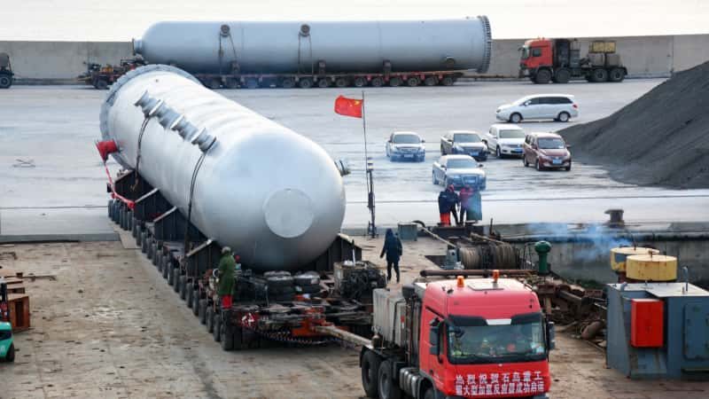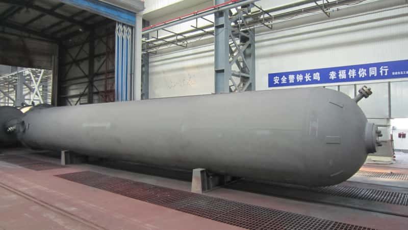

Corrosion failures in chemical pressure vessels rarely announce themselves in advance. A wall that looked acceptable at the last scheduled inspection develops a through-wall pit during a high-temperature acid wash cycle, and suddenly you’re looking at an unplanned shutdown, a hydrotest campaign, and a repair weld that may or may not satisfy your jurisdiction’s in-service welding procedure. That downtime has a cost — typically several times the price of the vessel itself when you account for lost production, emergency procurement of spare parts, and regulatory re-inspection fees. Specifying the wrong material grade, underestimating the corrosion allowance, or skipping an appropriate lining system at the purchase stage is almost always cheaper to fix on paper than on the plant floor.
Corrosion in chemical pressure vessels is caused by a combination of fluid chemistry, temperature, flow velocity, and weld microstructure. Carbon steel corrodes rapidly in acidic or chloride-bearing service. Stainless and duplex grades resist pitting but are vulnerable to stress corrosion cracking above certain temperature and chloride thresholds. Buyers should specify corrosion allowance, base material UNS designation, weld overlay or lining requirements, and PREN minimums before issuing an RFQ.
What most procurement specifications miss is not the material grade itself — it’s the interaction effects. A vessel that performs acceptably in dilute sulfuric acid at 40 °C can experience accelerated crevice attack under the same nominal specification if operating temperature climbs to 80 °C during summer campaigns, or if chloride concentration in the process stream drifts upward because upstream desalting efficiency drops. The gap between a vessel that lasts its design life and one that fails in year four is almost always traceable to a handful of specification decisions made before the first plate was cut.
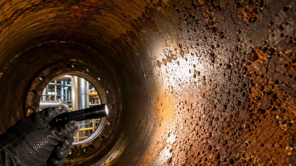
Eight Dominant Corrosion Mechanisms That Attack Chemical Pressure Vessels
Understanding which mechanism is actually threatening your vessel — not just “corrosion” in the abstract — determines whether you specify a corrosion allowance, an alloy upgrade, a fabrication requirement, a post-weld heat treatment, or all four. Each mechanism has a distinct driver, and conflating them leads to the wrong solution.
Uniform (General) Corrosion
This is electrochemical metal dissolution distributed across the exposed surface at a measurable, roughly predictable rate. It forms the entire basis for corrosion allowance calculations: ASME VIII Div.1 and GB 150 both allow the designer to add 1.5 mm to 6 mm of sacrificial wall thickness, the actual value depending on fluid aggressiveness, expected service life, and whether the rate is backed by coupon data or published tables. The critical procurement error is reading isocorrosion charts at average operating conditions. Sulfuric acid corrosion of carbon steel, for example, accelerates exponentially between 40°C and 80°C and again at concentrations crossing the 65–70 wt% threshold. Specify material for the credible operating extreme — startup acid dilution, upset temperature spikes — not the design-basis steady state.
Pitting Corrosion
Chloride, bromide, and fluoride ions locally break down the passive oxide film on stainless steels, initiating deep pits that penetrate wall thickness while the surrounding surface looks intact. PREN (Pitting Resistance Equivalent Number = %Cr + 3.3×%Mo + 16×%N) is the standard alloy ranking tool. Standard 316L carries a PREN of roughly 24–26. Duplex grades UNS S31803/S32205 exceed 35 — effectively doubling resistance to halide attack. Specify minimum PREN in the material requisition for any chloride-bearing stream above about 50 ppm Cl⁻. The process upset scenario matters enormously: a vessel designed for a “mild” treated-water service can pit aggressively when an upstream upset spikes chlorides to several hundred ppm during an unplanned bypass event.
Crevice Corrosion
Geometry drives this mechanism. Stagnant electrolyte trapped under gaskets, inside lap joints, beneath backing rings, or in dead-leg pipe stubs depletes oxygen and acidifies locally, creating conditions far more aggressive than the bulk fluid. Alloy selection helps, but fabrication specification is equally important: require full-penetration butt welds rather than fillet welds on all pressure-boundary joints, eliminate dead legs by design, and specify that backing rings be removed or replaced with consumable inserts. A vessel fabricated in a corrosion-resistant alloy but assembled with poor joint geometry will fail at the geometry, not the alloy.
Stress Corrosion Cracking (SCC)
SCC requires three simultaneous conditions: tensile stress, a susceptible alloy, and a specific environmental trigger. Chlorides attack austenitic stainless steels, even at modest concentrations above roughly 60–80°C. Amines attack carbon steel weld heat-affected zones in amine treating units. Caustic service embrittles low-alloy steels above concentration and temperature thresholds defined in NACE SP0472 and related documents. The inspection problem is severe — early SCC propagates sub-surface along grain boundaries with no visible surface signal. Post-weld heat treatment (PWHT) reduces residual tensile stress and is a procurement-enforceable requirement. Buyers should verify PWHT records, not just accept a mill certificate.
Visual inspection reliably detects stress corrosion cracking in its early stagesFalse
Early SCC propagates along grain boundaries sub-surface and produces no visible surface indication; detection requires wet fluorescent magnetic particle testing, phased-array UT, or TOFD at the appropriate inspection stage.
Galvanic Corrosion
Coupling dissimilar metals in a conductive process fluid creates a galvanic cell — the less noble metal accelerates its dissolution. Mixed-metallurgy vessels with carbon steel shells and stainless steel internals (trays, distributors, baffles) are common in practice and create exactly this geometry. The carbon steel shell becomes the anode in many process fluids. Buyers should specify dielectric isolation bushings at dissimilar-metal interfaces, or require that internal wetted components match the shell alloy. At minimum, the surface area ratio must favor the cathode being the smaller area — the reverse condition accelerates anode attack dramatically.
Erosion-Corrosion and Impingement
High fluid velocity and entrained solids strip the passive film faster than it can reform. Copper alloys become vulnerable above roughly 1–2 m/s in seawater or process condensate. Carbon steel in slurry service degrades rapidly above 3–5 m/s depending on particle hardness and size. Duplex stainless steels tolerate higher velocities — practical thresholds run 6–10 m/s in clean two-phase flow — but are not immune. Specify inlet impingement baffles, nozzle orientation away from vessel walls, and minimum wall thickness at high-velocity zones. The nozzle inlet specification is as important as the bulk material grade.
High-Temperature Hydrogen Attack (HTHA)
Above the thresholds plotted on the Nelson Curve (API 941), atomic hydrogen diffuses into carbon and low-alloy steel, reacts with carbides to form methane, and causes irreversible decarburization and fissuring. This is not a surface phenomenon — the damage is internal and sudden. Buyers in hydroprocessing, reforming, or high-pressure hydrogen service must require that the shell material heat number and heat treatment records be traceable and explicitly confirmed against the appropriate Nelson Curve operating limit, with a safety margin on temperature. Generic mill certificates are not sufficient; the specific heat’s carbon and alloy content must be documented.
Microbiologically Influenced Corrosion (MIC)
Sulfate-reducing bacteria (SRB) generate localized H₂S, producing aggressive pitting in water-containing vessels and in vessels that have been hydrostatically tested with untreated water and then left wet. MIC damage is often mistaken for pitting from chlorides until biological analysis confirms the mechanism. The control levers are in the acceptance procedure: specify potable or inhibited water for hydrotesting, biocide dosing to defined SRB kill levels, nitrogen blanketing during storage, and mandatory drying before vessel commissioning. These are procurement-enforceable line items, not site housekeeping suggestions.
How Process Conditions — Temperature, Pressure, pH, and Fluid Composition — Define the Corrosion Severity Class
Before a material specification can be written intelligently, the buyer needs a structured way to describe what the vessel actually sees. Listing a single bulk-fluid pH and calling it a day is how projects end up with undersized corrosion allowances and premature failures. The real task is translating all relevant process variables into a defensible severity class that maps directly to a material family and a fabrication strategy.
The Counterintuitive Concentration-Temperature Map for Common Corrosive Media
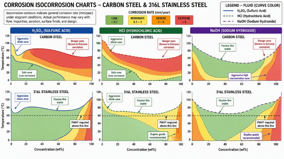
Sulfuric acid, hydrochloric acid, and caustic soda are the three fluids most frequently cited in corrosion-related vessel failures, and each one has a relationship with carbon steel that is not linear.
Sulfuric acid is the classic example of a counterintuitive profile. Dilute sulfuric acid — roughly 10 % to 65 % concentration — attacks carbon steel aggressively across a wide temperature range because the passive iron sulfate film cannot form reliably. At concentrations above approximately 75–80 %, the corrosion rate on carbon steel actually drops sharply because the acid becomes a powerful dehydrating agent that suppresses the electrochemical attack mechanism. That is why large carbon steel storage tanks for 93 % or 98 % H₂SO₄ are standard practice in industry. The danger is the boundary: a vessel designed for concentrated service that periodically receives diluted acid during washdown or process upset enters the worst possible region. Specifying materials only for steady-state concentrated conditions without analyzing dilution excursions has caused real failures.
Hydrochloric acid tolerates no such safe zone. Carbon steel corrodes in HCl across virtually all concentrations and temperatures, and the attack rate roughly doubles for every 10 °C rise. Above 50 °C and any measurable Cl⁻ concentration, carbon steel and standard 304/316L stainless steels both become problematic — 316L because of pitting and crevice attack at chloride levels above roughly 50 ppm depending on temperature and oxygen content. This is precisely the region where duplex grades (UNS S31803/S32205, PREN > 35) or higher alloys enter the specification.
Caustic soda presents caustic stress corrosion cracking (SCC) risk in carbon steel above roughly 60–80 °C at moderate concentrations (20–40 % NaOH), with the risk band shifting with temperature. Post-weld heat treatment becomes mandatory in these zones, not optional.
A Four-Tier Severity Classification for Practical Specification Work
A simple tiered framework lets a buyer communicate corrosion severity to vendors without writing a full corrosion engineering report.
| Severity Tier | Typical pH Band | Temperature | Halide / H₂S Level | Oxidizing Agents | Representative Service | Baseline Material Direction |
|---|---|---|---|---|---|---|
| Low | 6–9 | < 60 °C | < 10 ppm Cl⁻, no H₂S | Absent | Cooling water, clean condensate | Carbon steel, standard corrosion allowance 1.5–3 mm |
| Moderate | 4–6 or 9–11 | 60–120 °C | 10–200 ppm Cl⁻ or trace H₂S | Possible | Process water, dilute caustic, weak acids | 316L or low-alloy steel, corrosion allowance 3–4 mm |
| Severe | 2–4 or 11–13 | 120–200 °C | 200–2000 ppm Cl⁻ or H₂S partial pressure 0.05–0.35 MPa | Present | Sour gas scrubbers, acid wash columns, chloride-bearing process streams | Duplex SS, 317LMN, or weld overlay cladding; corrosion allowance 4–6 mm |
| Extreme | 13 | > 200 °C | > 2000 ppm Cl⁻ or H₂S > 0.35 MPa | Often present | Concentrated acid service, deep sour hydrocarbon, halide reactor environments | Alloy 625 / C-276 overlay or solid alloy construction; design-life-based analysis required |
Corrosion allowance ranges depend on design life (typically 15–25 years in refinery and chemical plant practice under ASME VIII Div.1 and GB 150) and on whether a liner or overlay is also specified. Overlay cladding with Alloy 625 or C-276 on a carbon steel shell can extend service life by 15–25 years in severe to extreme environments versus organic coating alone — the specific gain depends on operating temperature cycling frequency and acid excursion duration.
Increasing sulfuric acid concentration above ~75–80% reduces the corrosion rate on carbon steelTrue
At high concentrations, concentrated H₂SO₄ acts as a dehydrating agent that suppresses the electrochemical dissolution mechanism, making carbon steel a commercially accepted material for storage and transport of 93–98% H₂SO₄. This is well-established in NACE/AMPP and published corrosion engineering references.
Phase-Change Zones Deserve a Separate Severity Assessment
Bulk-fluid severity class is not enough on its own. Wherever the process fluid changes phase — at vapor-liquid interfaces, along shell courses near the liquid level line, at dewpoint condensation zones in overhead vapor nozzles, and at steam-process fluid boundaries in heat exchanger channels — local concentration effects can shift a moderate bulk service into a locally severe condition. Sulfuric acid mist condensing on a vapor-space shell course at a slightly lower temperature is no longer the bulk concentration; it can be far more dilute and far more corrosive. This is why specifying a single material grade for the entire vessel shell is often wrong. Different shell courses, specific nozzles, and internal baffles in phase-change zones sometimes warrant a different alloy selection or a localized weld overlay.
Transient Conditions Set the True Specification Ceiling
Steady-state design point is where many specifications stop. It should be where they start. Startup and shutdown cycles routinely expose vessel internals to oxygen-saturated water, steam condensate with dissolved CO₂, and cleaning-in-place (CIP) chemicals — often caustic followed by dilute acid — that are more aggressive than normal operating chemistry. A vessel that handles 15 % HCl at 40 °C in normal operation might see a caustic clean at 80 °C followed by a 5 % acid rinse every quarter. That worst credible condition — not the steady-state — is the specification anchor.
Requesting a Corrosivity Assessment Datasheet from Vendors
Buyers can enforce this thinking contractually. A corrosivity assessment datasheet, included as a required deliverable in the technical bid package, asks the vendor or engineering contractor to explicitly document: all process fluid compositions including upset and cleaning chemistry, temperature and pressure ranges including transients, phase distribution along the vessel, and the resulting severity tier assignment for each zone. This shifts the accountability for catching boundary conditions from informal conversation to a reviewed and signed document. It also creates the audit trail regulators and insurers want if a failure occurs later.
Selecting Base Materials: Carbon Steel, Low-Alloy Steel, Stainless Grades, Nickel Alloys, and Non-Metallics Compared
Material selection is where severity-class thinking from earlier sections converts into a purchase order line item. Getting this wrong costs more than the premium you saved — plan for a mid-cycle reline, an unplanned turnaround, or a fitness-for-service assessment that grounds the vessel for months.
Carbon Steel and Low-Alloy Steel (SA-516, SA-387)
SA-516 Gr. 70 remains the backbone of chemical vessel construction for a reason: it is weldable, widely available in heavy plate, and cheap enough that you can afford a generous corrosion allowance. That allowance typically runs 1.5 mm to 6 mm depending on fluid aggressiveness and the intended design life — a 20-year vessel in dilute caustic sits toward the lower end, while a vessel handling wet sour gas (H₂S + CO₂ service) under NACE MR0175 requirements pushes toward the upper end or requires supplementary inhibitor injection.
SA-387 Cr-Mo grades step in when elevated temperature creep and hydrogen attack become concerns — typically above 230–260 °C in hydrogen-rich or hydrocarbon streams. The Nelson curves govern this selection. Where temperatures are moderate and the fluid is neither acidic nor oxidizing, carbon steel with proper allowance and an internal coating is still the economically correct answer. The moment you cross into acidic pH below roughly 4.5, elevated chlorides, or oxidizing acids, that calculus flips sharply.
304L and 316L Austenitic Stainless Steels
The widely cited threshold — avoid austenitic stainless above 60 °C and 200 ppm Cl⁻ — is a useful starting point that gets misapplied constantly. Real-world limitations matter. Chloride concentration at the bulk fluid level is not the same as the concentration at crevices, under deposits, or in vapor-phase condensate zones, where local Cl⁻ can spike by an order of magnitude. A vessel bulk-fluid spec of 150 ppm Cl⁻ at 55 °C is not automatically safe in 316L if it runs periodic steam-out cycles or accumulates scale.
316L gains meaningful pitting resistance over 304L through the molybdenum addition, pushing its PREN from roughly 18–20 up to 24–26. That is still well below duplex territory. Weldability is generally good, but heat input control and post-weld pickling matter: a sensitized heat-affected zone in a 304L vessel will corrode selectively in oxidizing acids even when the base metal would not.
Duplex and Super-Duplex (2205, 2507)
UNS S31803/S32205 (2205) carries a PREN above 35 — roughly double that of 316L — making it a standard upgrade specification for chloride-bearing streams above 50 ppm Cl⁻ where temperatures push past the austenitic comfort zone. Offshore produced-water separators, seawater-cooled pressure vessels, and chlorinated solvent service are the clearest lifecycle-value applications. Super-duplex (2507, PREN above 40) extends this envelope further into aggressive seawater and mixed chloride-acid environments.
The fabrication risk that buyers must control: intermetallic sigma-phase precipitation occurs if weld heat input runs high or post-weld cooling is too slow, typically in the 700–900 °C range. A vessel fabricated without heat-input records and solution-annealing verification on heavy sections can have HAZ toughness and corrosion resistance well below what the mill certificate shows.
Duplex stainless weld procedure qualification automatically ensures correct phase balance in production weldsFalse
WPS qualification establishes parameters but cannot substitute for production weld monitoring, heat input records, and periodic ferrite measurement on actual shop welds. Phase balance must be verified throughout fabrication, not assumed from a qualified procedure alone.
Nickel-Based Alloys (Alloy 625, C-276, Alloy 20, Incoloy 825)
These materials define the upper boundary of metallic resistance. Alloy C-276 (UNS N10276) handles wet chlorine, concentrated HCl, and mixed-acid services where nothing else lasts. Alloy 625 (UNS N06625) is the standard weld overlay consumable for cladding carbon steel shells in strong acid or halide environments — weld overlay rather than solid construction cuts material cost significantly while extending service life by 15–25 years versus carbon steel with organic coating, based on published refinery turnaround data.
Buyers specifying nickel alloys must go beyond the trade name. Specify the UNS number, product form (plate, forging, pipe), and heat treatment condition explicitly. “Hastelloy C” without a UNS call-out has been used to justify delivery of C-4 or C-22 when C-276 was intended — different corrosion performance in reducing acid environments. Alloy 20 (UNS N08020) is purpose-built for sulfuric acid service across a wide concentration range; Incoloy 825 (UNS N08825) covers moderate acid and chloride duty at lower cost than C-276 where the full aggressive spectrum is not present.
Titanium (Grade 2 and Grade 12)
Grade 2 titanium is nearly immune to oxidizing acids and chloride solutions that destroy stainless steels. In seawater heat exchanger channels and wet chlorine service it outlasts most alternatives. Grade 12 adds nickel and molybdenum for improved resistance to reducing acids and crevice corrosion.
Weight savings over nickel alloys run 40–50% for equivalent wall thickness, which matters for large-diameter vessels and rotating equipment. Cost per kilogram is high, but lifecycle cost often favors titanium over nickel alloys in thin-walled, high-surface-area configurations. The fabrication constraints are non-negotiable: inert gas purging of both sides of the weld is mandatory (oxygen contamination above roughly 150 ppm embrittles the HAZ), welding procedures must be qualified per ASME Section IX with titanium-specific shielding protocols, and your RFQ must explicitly call these out — not all fabricators maintain qualified titanium procedures.
FRP and Lined Vessels
For highly corrosive services at lower pressures — typically below 10–15 bar depending on diameter and temperature — fiber-reinforced plastic or lined steel vessels can be the right answer. FRP works well for dilute acid storage, scrubber shells, and atmospheric or low-pressure chemical service. Lined vessels (HDPE, PTFE, rubber, or glass-flake epoxy liner inside a carbon steel shell) extend this logic to cases where structural pressure rating must come from steel but the process fluid is incompatible with any metal.
Buyers must specify three things independently: the liner material and its chemical compatibility data sheet for the actual service fluid, the bond integrity testing method (spark testing, holiday detection, peel test per applicable standard), and the structural shell design standard. A PTFE liner in a vessel designed only to the liner manufacturer’s standard — with no independent structural calculation for the steel shell — has caused catastrophic failures when internal pressure exceeded design assumptions. Specify each component of the system separately.
Specifying Corrosion Allowance, Weld Overlay Cladding, and Loose Lining: When Each Strategy Applies
Most procurement specifications treat corrosion protection as a single dial — add more metal, or add a coating, and move on. That conflation gets expensive. The three primary strategies — corrosion allowance, metallurgical weld overlay, and mechanical loose lining — serve fundamentally different functions, carry different fabrication constraints, and fail in different ways if misapplied. Knowing which one fits your service environment before the data sheet is issued saves far more than it costs.
Corrosion Allowance: What the Standards Actually Require and Where It Falls Short
Both ASME VIII Div.1 and GB 150 treat corrosion allowance (CA) as an additive term in the minimum required wall thickness calculation. The designer computes the pressure-governed thickness, then adds CA on top. In practice, specified CA ranges from 1.5 mm for mild process fluids with a short design life to 6 mm for moderately aggressive services with a 20-year-plus horizon. Where it falls — closer to 1.5 mm or closer to 6 mm — depends on corrosion rate from coupon or plant history data, design life, and whether in-service inspection access is feasible.
The operational trap is assuming that a generous CA solves an aggressive corrosion problem. It does not. A vessel in concentrated sulfuric acid or high-chloride brine losing 0.8–1.2 mm per year will exhaust even a 6 mm CA within one inspection interval. Beyond the chemistry, thick shells drive up welding heat input, which can sensitize stainless grades or create wider heat-affected zones in low-alloy steels — regions that corrode faster than the base material. Weight penalties also compound: each extra millimeter of wall on a large-diameter vessel adds real structural and foundation load. CA is the right answer for genuinely mild corrosion with known, low uniform corrosion rates. It is the wrong answer when the dominant mechanism is pitting, crevice corrosion, or stress corrosion cracking.
Weld Overlay Cladding: Metallurgical Bond for High-Severity Zones
Weld overlay (WO) deposits a corrosion-resistant alloy directly onto the carbon or low-alloy steel shell, creating a true metallurgical bond — not an adhesive interface. Common overlay systems start with a 309L or 309LMo butter layer to dilute carbon pickup, followed by a finish layer of 316L, Alloy 625 (UNS N06625), or Alloy C-276 (UNS N10276) depending on halide concentration and acid strength. Minimum finished overlay thickness is typically 3 mm after machining, consistent with ASME Section IX qualification requirements, though 4–5 mm is common when the finish layer must independently resist pitting without dilution zones reaching the surface.
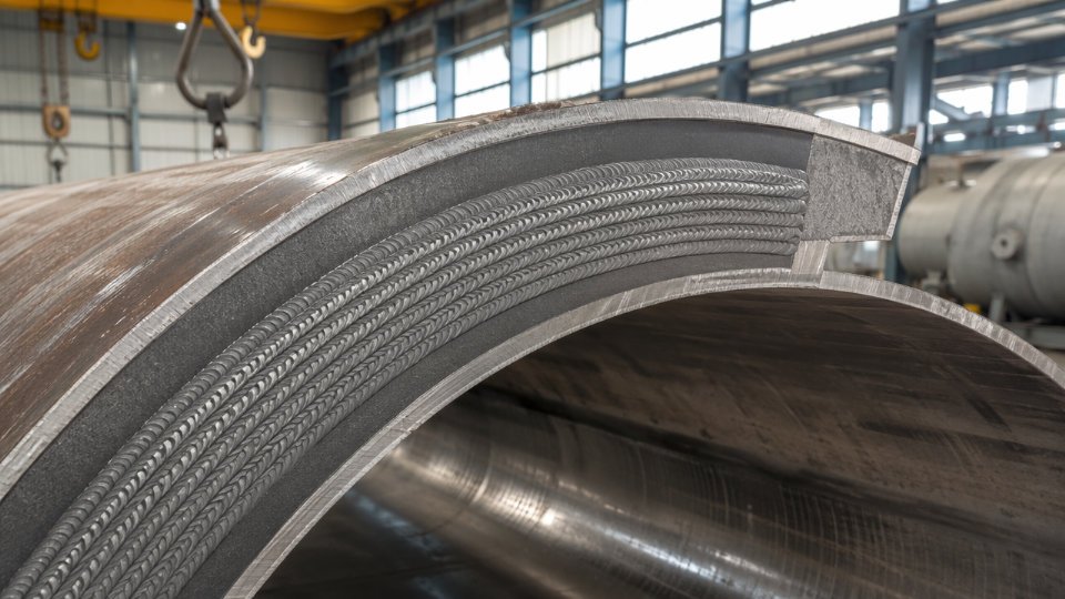
Buyers must require positive material identification (PMI) on every completed overlay zone — not just on incoming consumables — and ferrite content measurement per AWS A4.2 on austenitic overlays, since ferrite below roughly 3 FN can indicate dilution-driven sensitization risk. These requirements belong in the Inspection and Test Plan, with hold points, not just in a general material note on the drawing.
Duplex stainless overlays (UNS S31803/S32205) are increasingly specified for chloride-bearing streams above 50 ppm Cl⁻. Their PREN exceeds 35 — roughly double that of 316L — which meaningfully shifts the threshold for pitting initiation in warm brines or produced water services. Published refinery turnaround data suggest that Alloy 625 or C-276 overlays extend vessel service life by 15–25 years compared with carbon steel using organic coating alone, though actual results depend heavily on process upset frequency and inspection discipline.
Weld overlay cladding creates a metallurgical bond that organic coatings cannot replicate, making it suitable for continuous immersion in strong acids and high-chloride streams.True
Unlike paint or epoxy systems, weld overlay fuses the corrosion-resistant alloy into the substrate. This eliminates the adhesive interface that fails by permeation or mechanical disbonding under thermal cycling, a distinction confirmed by ASME Section IX and industry corrosion engineering practice.
Explosion-Bonded and Roll-Bonded Clad Plate: Large-Area Economics
Where weld overlay is impractical across large shell sections — typically vessels above roughly 3 m diameter or with extensive flat surfaces — explosion-bonded or roll-bonded clad plate offers comparable metallurgical continuity at lower fabrication cost per square meter. The bond quality is not optional to verify: buyers must specify shear bond strength testing per ASTM A264 (for stainless clad) or ASTM A265 (for nickel alloy clad), with minimum shear strength typically 140 MPa, plus ultrasonic bond integrity scanning to detect unbonded patches before plate is rolled into shell courses.
Cladding thickness tolerance and edge preparation requirements are frequently omitted from buyer specifications — an omission that matters. At weld seams, the clad layer must be butter-welded before the structural weld is completed; failing to specify this sequence leads to disbonding at the heat-affected zone, exactly where corrosion then initiates.
Loose Liners: Polymer, Rubber, and Ceramic for Non-Metallic Protection
PTFE, rubber lining, glass-flake epoxy, and ceramic tile liners attach mechanically rather than metallurgically. Their appropriate envelope is comparatively narrow: PTFE liners are typically rated to 150–180 °C continuous service, and thin glass-flake systems rarely exceed 90–100 °C before permeation risk rises sharply. Pressure cycling is particularly hard on bonded rubber and epoxy systems; differential thermal expansion at cyclic conditions drives blister formation behind the liner, and once moisture accumulates at the steel interface, the substrate corrodes invisibly.
For any polymer liner, holiday (pinhole) testing voltage and acceptance criteria must appear explicitly in the ITP. A common benchmark is 67.5 V per 25 µm of lining thickness for immersion-grade epoxy, with zero holidays as the acceptance criterion on all immersed zones. Skipping this test and discovering disbonding after commissioning means a vessel drain, scaffold, blast, reline, and delay that typically costs more than the original liner.
Multi-Zone Vessels: Specifying Zone Boundaries Explicitly
A sour-service pressure vessel with a bottom water phase, a middle hydrocarbon phase, and a gas cap above is not one corrosion problem — it is three. The water phase may warrant Alloy 625 overlay or rubber lining; the hydrocarbon section may tolerate a corrosion allowance on carbon steel; the gas-phase shell may require only a modest CA with H₂S-specific hardness control per NACE MR0175. Each zone boundary must appear as a defined elevation on the vessel sketch or data sheet, with the transition weld and its inspection requirement explicitly called out. Leaving zone boundaries implicit invites fabricators to apply the cheapest strategy uniformly — which optimizes their cost, not your vessel’s service life.
| Protection Strategy | Best Fit | Key Buyer Specification Point | Avoid When |
|---|---|---|---|
| Corrosion allowance | Uniform, low-rate corrosion; accessible for UT | CA value, design life, corrosion rate basis | Pitting, SCC, or corrosion rate > 0.3 mm/yr |
| Weld overlay cladding | High-severity acids, halides, localized zones | Overlay alloy, finish thickness, PMI + ferrite ITP hold | Large flat areas (cost inefficient vs. clad plate) |
| Explosion/roll-bonded clad plate | Large shell areas, moderate-to-severe service | ASTM A264/A265 bond test, UT scanning, edge prep spec | Tight-radius nozzles or complex geometries |
| Loose liner (PTFE/rubber/ceramic) | Strong acids, alkalis; lower temperature | Holiday test voltage, acceptance criteria, T/P limits | High thermal cycling, pressure surges, > liner T limit |
Writing a Corrosion-Complete Vessel Data Sheet and RFQ: Fields, Language, and Common Omissions
A well-executed corrosion analysis is worthless if the conclusions never make it into the purchase document. Vendors quote what buyers specify. If the data sheet omits chloride concentration or leaves corrosion allowance as a single vessel-wide number, fabricators will default to the minimum their applicable code permits — which may be entirely wrong for your actual service. Getting this right requires deliberate field-by-field discipline, not a boilerplate template.
Minimum Corrosion-Related Fields the Data Sheet Must Carry
Every corrosion-relevant parameter needs its own line. A vessel operating in a single-phase sulfuric acid service has a fundamentally different corrosion profile than one handling the same nominal fluid with 150 ppm chloride contamination from cooling water ingress. The data sheet must capture both the design case and the credible upset.
Required fields, at minimum:
- Design corrosion allowance, by zone — shell, heads, nozzles, and any internal structural members rated separately. A single vessel-wide value is acceptable only for genuinely uniform service.
- Corrosion severity class — carry forward the class from your process analysis (Mild, Moderate, Severe, Extreme) so the fabricator’s materials engineer can cross-check the base metal selection immediately.
- Fluid composition including trace contaminants — list all known species, not just the primary process fluid. Specify chloride content in ppm, H₂S partial pressure in kPa (not just presence/absence), and dissolved oxygen if relevant.
- Operating temperature range including upset — state normal operating, maximum continuous, and credible peak upset separately. A vessel designed for 80 °C normal service but subject to 130 °C steam-out episodes needs to be assessed at both extremes.
- pH range — minimum, maximum, and the upset floor.
- H₂S partial pressure — this determines NACE MR0175/ISO 15156 scope. The threshold that triggers the standard is a H₂S partial pressure above 0.0003 MPa (0.05 psia) in a system with free water at total pressures above 0.4 MPa (65 psia). Below those dual thresholds the standard does not apply; above them it binds weld hardness, base metal hardness, and alloy selection. Reference it explicitly in the RFQ: “All wetted pressure-retaining components and welds shall comply with NACE MR0175/ISO 15156 Part 2 [or Part 3 for CRAs] — maximum weld hardness 22 HRC per Table A.2 unless alternative hardness limits are agreed per Annex A procedure.”
Material Family vs. a Specific UNS Number with Product Form
Specifying “stainless steel” allows a vendor to propose 304L, 316L, 317L, or a dozen duplex grades — all technically stainless, none corrosion-equivalent for your service. The purchase document must state the UNS number (e.g., UNS S31803), the product form (plate per ASTM A240, pipe per ASTM A790, or fittings per ASTM A815), the required heat treatment condition (solution-annealed), and the mill certificate type (EN 10204 3.1 or 3.2). Without that specificity, a vendor is contractually free to substitute an “equivalent” grade that passes dimensional checks but fails your corrosion resistance requirement. Duplex 2205 and lean duplex 2101 are both “duplex stainless” — one carries a PREN above 35, the other typically sits below 26.
ITP Hold Points That Corrosion Resistance Depends On
The inspection and test plan is where corrosion specification either gets enforced or quietly evaporates. Four hold points matter most:
PMI (positive material identification) — required at raw material receipt before any cutting begins, and again after weld overlay deposition to confirm the deposited chemistry matches the specified filler classification. Specifying PMI only at incoming inspection misses overlay errors.
Ferrite content on austenitic welds — typically 3–8 FN for 316L welds in corrosive service; excessive ferrite can reduce corrosion resistance, insufficient ferrite increases hot cracking risk. Specify the acceptable range and the measurement method (Fischer Feritscope or equivalent) as a witness point.
Weld hardness after PWHT — for any vessel in NACE MR0175 scope, hardness testing of production weld coupons and accessible weld cap surfaces is a hold point, not a review point. The vendor cannot proceed to hydrostatic test until results are accepted.
Holiday testing on linings — any organic lining, rubber lining, or loose liner requires spark testing per NACE SP0188 or equivalent at a hold point before vessel closure.
The Hydrostatic Test Water Omission That Causes SCC
This is the most consistently overlooked field in RFQs for stainless steel vessels. Hydrostatic test water for austenitic stainless components should contain below 25 ppm Cl⁻ — some operators tighten this to below 10 ppm for 316L in warm climates where the vessel may stand filled for days. Specify the chloride limit, require the vendor to submit a test water analysis certificate before the hydro, and include a post-test requirement: drain within a defined window (typically 24–48 hours), blow dry with clean dry air or nitrogen, and apply nitrogen blanketing for storage. These are enforceable purchase order special requirements and cost almost nothing to add.
Hydrostatic test water chloride above 50 ppm has caused stress corrosion cracking in austenitic stainless pressure vessels during the standing test period before the vessel ever entered service.True
SCC of austenitic stainless steels in chloride-containing water at ambient temperature is well-documented. The combination of residual fabrication stress, standing water contact time, and chloride concentration above threshold can initiate cracking. This is addressed in ASTM A380 and referenced in multiple fabrication standards for corrosion-resistant vessels.
Handling Conflicting Code Jurisdictions
An ASME-stamped vessel destined for a European PED market, or one where the buyer needs both ASME U-stamp and a GB 150 equivalency declaration for a joint-venture plant, creates a material traceability problem. ASME Section II material specifications (SA-240, SA-516) do not automatically satisfy PED Module H requirements for third-party certification, and GB 150 accepts specific Chinese GB/T material standards that have no direct ASME equivalent. Specify explicitly: which code governs the pressure design calculation, which material standards are acceptable for each code, and what documentation is required (Material Test Report format, third-party inspection authority, and whether dual-stamping is required). Require the vendor to submit a compliance matrix at the RFQ response stage — not after award. Discovering a Chinese-mill plate with GB/T 24511 certification cannot be accepted under an ASME U-stamp job after fabrication begins is expensive for everyone.
Evaluating Vendor Corrosion-Related Manufacturing Capabilities Before You Award the Contract
A vendor who holds an ASME U-stamp and quotes a competitive price is not automatically capable of fabricating a duplex stainless vessel for a chloride-rich process stream or a C-276 overlay reactor for a halide acid service. The stamp certifies a quality system; it does not certify metallurgical competence in corrosion-critical alloys. Pre-award technical evaluation is where buyers separate real capability from paper credentials.
Weld Procedure Qualification Records
Request the actual WPQRs, not just a list of approved WPS numbers. For corrosion-critical alloys, check that the base metal P-number grouping matches your specified material exactly — a procedure qualified on 316L (P-8) does not automatically cover duplex UNS S31803 (P-10H). Verify the filler metal classification and confirm it matches the overlay or weld chemistry you specified. For duplex grades, interpass temperature limits are a serious fabrication control; records should show limits held to 150°C maximum (lower limits are common at some shops). Look for PWHT cycle records with actual time-at-temperature curves, not just the target parameters. Ask specifically whether corrosion test coupons were run: ASTM A262 Practice E (the Strauss test) is the standard sensitization screen for austenitic stainless grades, and its absence from a WPQR for a vessel intended for acidic or oxidizing service is a gap worth challenging directly.
In-House PMI Program
Positive material identification should be embedded in the fabrication workflow, not offered as an optional add-on. A vendor who proposes subcontracting PMI to a third party only when the buyer requests it is telling you that material mix-up control is not routine in their shop. Ask whether they use calibrated handheld XRF analyzers with documented calibration intervals and a written PMI procedure that specifies trigger points: at material receiving, after cutting, and after each welding stage on corrosion-alloy components. On nickel-alloy or duplex vessels, a carbon steel fitting installed by mistake will initiate accelerated galvanic or pitting attack within months.
Handheld XRF analyzers cannot reliably distinguish UNS S31803 duplex from 316L austenitic stainless by iron/chromium ratio alone — nickel and molybdenum content confirmation is required.True
Duplex S31803 and 316L share overlapping Cr ranges; the key differentiators are Mo (~3.1–3.5% in S31803) and the lower Ni content (~4.5–6.5% vs. 10–14% in 316L). A calibrated XRF unit measuring full alloy composition can make this distinction, but operators must know which elements to verify and report.
Overlay Welding Equipment and Dilution Control
For Alloy 625 or C-276 weld overlay, automated processes — GTAW hot-wire or SAW strip cladding — produce tighter dilution control (typically 5–15% iron dilution) than manual SMAW, which can reach 20–30% and degrade corrosion resistance. Ask the vendor to show equipment type, dilution test records from production coupons, and chemical analysis confirming overlay chemistry meets the specified minimum alloy content. A vendor who cannot provide production coupon chemistry from recent jobs involving the same overlay consumable should not be awarded a vessel for strong acid or halide service.
Lining Application Environment Controls
For rubber lining and FRP construction, surface preparation and environmental conditions during application govern long-term adhesion more than any other variable. Require documentation of surface preparation to Sa 2.5 minimum per ISO 8501-1, along with continuous humidity and dew-point monitoring records during blasting and lining application. Cure-cycle logs should show actual temperature profiles, not just target values. A vendor who cannot produce these records from a recent lining job is likely not controlling them.
NDE Portfolio for Corrosion-Resistant Construction
Radiography has geometric limitations in clad and overlay vessels — the weld cap geometry and overlay thickness scatter the beam and reduce sensitivity. Confirm the vendor has TOFD and phased-array UT capability and qualified procedures for examining welds in clad construction. Wet fluorescent magnetic particle testing is required for NACE-scope carbon steel components where dry MT would miss tight stress-corrosion cracking precursors. For overlay or cladding disbond detection — a failure mode that accelerates dramatically once a hot, corrosive process fluid contacts the substrate — ask whether the vendor can perform ACFM or eddy-current scanning, or has a qualified subcontractor with documented procedures.
Reference Project Traceability
Ask for data books from prior projects involving the same alloy combination you are specifying, not a general reference list. A data book from a comparable vessel should show signed ITP hold-point records, NDE reports with actual indications and dispositions, PMI logs, and overlay chemistry results. If a vendor’s data book contains only cover pages and test certificates without the actual inspection records attached, the ITP was probably managed on paper rather than on the shop floor. That distinction matters when your vessel is running at 180°C in a chloride service and you need to trust the construction integrity rather than hope for it.
In-Service Corrosion Monitoring, Inspection Intervals, and Remaining-Life Estimation for Operating Vessels
The material choices made at the specification stage do not stop mattering once the vessel ships. They directly determine how often you inspect, what monitoring hardware you install, and whether the vessel reaches its design life without forced retirement. Buyers who treat upfront material investment as a cost to minimize frequently discover that the savings disappear inside three inspection cycles — through higher UT scanning labor, shortened intervals, and early replacement.
Risk-Based Inspection Under API 510 and Why Your Corrosion Allowance Documentation Matters
API 510’s risk-based inspection framework scores vessels on two axes: probability of failure (PoF) and consequence of failure (CoF). The PoF score is heavily driven by corrosion rate confidence. A vessel with a well-documented initial corrosion allowance — say, 3 mm specified against a confirmed sulfuric acid service at 6 to 8 wt% — and two or three years of measured wall-thickness trend data can be assigned a lower PoF than a nominally identical vessel whose corrosion rate is assumed from generic tables. That lower PoF score directly extends the allowable inspection interval, often from 5-year cycles to 8 or 10 years depending on the consequence tier. For a vessel requiring scaffolding and confined-space entry, that interval difference can represent $50,000 to $200,000 in inspection cost per cycle, depending on vessel size and plant location. The lesson is not complicated: document your corrosion allowance basis in the original data sheet, keep the corrosion rate calculations in the vessel file, and update them after every inspection.
Continuous and Periodic Monitoring Techniques
Electrical resistance (ER) probes measure cumulative metal loss by tracking the resistance increase of a sacrificial element as it corrodes. They work in non-conductive and multiphase streams where electrochemical methods fail, and they suit continuous data logging — typical logging intervals run from hourly in high-severity services to daily in moderate ones. Linear polarization resistance (LPR) probes measure instantaneous corrosion rate electrochemically, making them better for detecting rapid rate excursions caused by process upsets like pH swings or inhibitor injection failures. Install LPR probes where aqueous phase contacts the shell: bottom-of-line positions in horizontal vessels, inlet nozzle zones, and any known dead-leg areas.
Ultrasonic thickness scanning grids remain the backbone of periodic inspection. A defined grid — typically 50 mm to 150 mm node spacing depending on expected corrosion uniformity — applied at the same reference points each outage gives you the wall-loss rate curve that feeds every remaining-life calculation. Grid density should increase around welds, heat-affected zones, and areas downstream of flow disturbances.
Hydrogen Flux Monitoring for HTHA and HIC Service
Hydroprocessing and sour gas vessels face hydrogen damage mechanisms that UT scanning alone cannot detect before cracking initiates. Hydrogen permeation probes — operating on the Devanathan-Stachurski electrochemical cell principle — measure the flux of atomic hydrogen diffusing through the vessel wall. Rising permeation current signals increasing hydrogen charging, giving operators days to weeks of warning ahead of measurable crack growth. These probes are particularly valuable on C-0.5Mo and Cr-Mo vessels operating near the Nelson curve limits. If your vessel specification did not include a permeation monitoring provision and the service is sour or high-partial-pressure hydrogen, adding it during the next turnaround is worth the installation cost.
Fitness-for-Service Assessment: API 579-1/ASME FFS-1
When inspection reveals wall loss or localized thinning, the default instinct — replace the vessel — is rarely necessary and often the wrong economic decision. API 579-1/ASME FFS-1 provides three assessment tiers. Level 1 uses conservative screening curves requiring only basic thickness measurements and original design data; most plant engineers can run it with inspection records in hand. Level 2 applies more refined stress analysis to local thin areas and allows a larger fraction of detected damage to be screened as acceptable. Level 3 involves detailed finite-element analysis or specialist fracture mechanics and applies to crack-like flaws or complex damage interaction. An FFS assessment converts “we found corrosion” from a shutdown trigger into a documented, defensible engineering conclusion about whether continued operation is safe and for how long.
An FFS assessment under API 579-1/ASME FFS-1 can confirm continued safe operation of a vessel with detected corrosion, avoiding immediate replacement.True
API 579-1/ASME FFS-1 is a published consensus standard from API and ASME that provides accepted engineering methods for evaluating pressure equipment with known flaws or degradation; Level 1 through Level 3 assessments are widely used in refinery and chemical plant practice to extend equipment life based on measured damage and calculated remaining strength.
Remnant Life Calculation and Setting the Next Inspection Date
The core calculation is straightforward: divide the remaining corrosion allowance — measured wall thickness minus the minimum allowable wall thickness from the original design — by the confirmed corrosion rate in mm per year. If a vessel has 2.1 mm of remaining allowance above minimum and a confirmed rate of 0.18 mm/year, the calculated remnant life is roughly 11 to 12 years. Inspection practice typically applies a fraction of that figure — commonly 50% for the next internal inspection interval — to ensure the vessel is re-evaluated before the allowance is consumed. What this calculation demands is a reliable corrosion rate, not a default assumption. That rate comes from UT grid trending across multiple inspection cycles. A single-point measurement is insufficient. Vessels with fewer than two data points on their corrosion rate curve carry implicit uncertainty that API 510 RBI methodology penalizes with a higher PoF score — pushing inspection intervals shorter, not longer.
The operational warning here is direct: vessels specified with inadequate corrosion allowance or without continuous monitoring hardware arrive at mid-life with thin walls, uncertain rates, and inspection intervals that compress just as the plant has matured and outage costs have risen. The upfront specification decision and the twenty-year inspection budget are the same decision, made at different times.
Frequently Asked Questions About Corrosion in Chemical Pressure Vessels
What is the standard corrosion allowance for a chemical pressure vessel, and how is it determined?
There is no universal standard value. Both ASME VIII Div.1 and GB 150 explicitly leave corrosion allowance to the designer’s engineering judgment rather than mandating a fixed number. The correct approach is to establish the actual or conservatively estimated corrosion rate for your specific fluid-material pair — from published corrosion databases, coupon test data, or operating history on analogous service — and multiply that rate by the intended design life. In practice, values run from 1.5 mm for relatively mild aqueous service on austenitic stainless steel up to 6 mm or more for aggressive acid or sour service on carbon steel, with the spread depending on fluid aggressiveness, velocity, temperature, and whether intermittent or continuous contact occurs. Specifying a round number without backing it up with a documented corrosion rate and design life is a procurement error that either wastes material cost or, worse, under-protects the vessel.
When should I specify duplex stainless steel instead of 316L?
The practical triggers: chloride concentration above roughly 200 ppm at process temperatures above 50°C, any service combining chloride pitting risk with a meaningful general corrosion duty, or a design where higher strength (duplex yield strength is typically 1.7–2× that of 316L) allows a thinner wall and reduces overall vessel weight. Duplex grades such as UNS S31803/S32205 carry a PREN above 35, roughly double that of 316L, which matters directly in chloride-bearing streams. One important caveat: duplex requires tighter weld procedure qualification and heat input control than 316L. Overheating during welding can precipitate intermetallic phases that destroy both toughness and corrosion resistance. If your fabricator cannot demonstrate WPS/PQR records with documented ferrite content checks and impact testing on duplex weldments, the material upgrade means nothing.
Does PWHT help or hurt corrosion resistance?
It depends entirely on the alloy, and this is one of the more common misunderstandings in vessel procurement. For carbon steel and low-alloy steels (P1, P4, P5 groups), PWHT reduces residual stress and significantly lowers susceptibility to stress corrosion cracking and hydrogen-induced cracking — it is protective and often code-mandatory. For standard austenitic stainless steels such as 304 and 316, PWHT in the sensitization range (roughly 425–815°C) causes chromium carbide precipitation at grain boundaries, which destroys intergranular corrosion resistance. Specifying PWHT on a 316 vessel without qualifying the temperature range is how you inadvertently create a vessel that fails faster than plain carbon steel would have.
PWHT universally improves corrosion resistance in pressure vessels regardless of materialFalse
PWHT reduces SCC risk in carbon and low-alloy steels but can cause sensitization in standard austenitic stainless steels, degrading intergranular corrosion resistance — the correct treatment is alloy-specific.
What chloride limit should I specify for hydrostatic test water on stainless steel vessels?
Industry practice is 25 ppm Cl⁻ maximum for 304 and 316 grades. Tighten that to 10 ppm or below for super-austenitic or duplex grades. Equally important — and frequently omitted from purchase documents — is requiring the vessel be drained and dried within a defined window after testing, typically 24–48 hours. Pooled test water left sitting in a horizontal vessel or in low-point dead legs will concentrate chlorides through evaporation and can initiate pitting before the vessel ever enters service. Specify both the water quality limit and the post-test drying requirement explicitly in the inspection and test plan.
How do I know if my service falls within the scope of NACE MR0175 / ISO 15156?
The standard applies when the process contains H₂S in the gas phase, the partial pressure of H₂S exceeds 0.0003 MPa (0.05 psia), and either the system pH is below 3.5 or the aqueous conditions defined in Part 1 of the standard are met. The scope determination is not a judgment call made informally during a kickoff meeting — work through the checklist in ISO 15156 Part 1, document your inputs (H₂S partial pressure, pH, temperature, chloride concentration, elemental sulfur presence), and record the conclusion on the vessel data sheet. Vendors who ask you to confirm scope verbally without documented process data are cutting a corner that becomes a liability dispute after the first inspection finds cracking.
Can I use carbon steel with a thick epoxy coating instead of upgrading to stainless steel?
Coatings are legitimate for mild to moderate service where the coating remains inspectable and can be reapplied during planned maintenance windows. They are not a substitute for alloy selection in three situations: where a coating holiday causes rapid localized attack because the underlying substrate has no inherent corrosion resistance; where process temperature exceeds the coating system’s rated limit (many industrial epoxies are qualified only to 90–120°C, and immersion service degrades that further); or where in-service mechanical cleaning will physically damage the coating. Weld overlay cladding with Alloy 625 or C-276 is the appropriate answer for strong acid or halide environments where coating failure is not a recoverable event — service life extension of 15–25 years relative to coated carbon steel reflects published refinery turnaround experience, though actual results depend on acid concentration, temperature, and velocity.
What documentation should I require from a vendor to verify corrosion-resistant material quality?
The minimum traceable package: mill test certificates with heat numbers traceable to the as-built vessel drawing, positive material identification records covering all pressure-retaining alloy components, WPS and PQR records that include corrosion test data for any overlay or clad welds, PWHT time-temperature charts with thermocouple placement maps, and ITP sign-off sheets with hold-point witness records. For duplex or nickel-alloy vessels, add ferrite content measurements on production welds and, where specified, corrosion test results per ASTM A923 or G48. Without heat-number traceability from the mill certificate through to the as-built drawing, the MTC is a piece of paper with no evidentiary value. Require it in the contract, not as an afterthought at data book submission.