
A vessel connection can match the piping layout while the purchasing documents still leave its loading undefined. To resolve that gap, the specification needs more than a nozzle size, pressure class and orientation drawing.
Include signed forces and moments in all three axes for each relevant piping-load case, together with units, coordinate definitions, the application point, associated pressure and temperature, and the source revision. State which components act simultaneously and how the loads will be compared with equipment limits. Identify the parties responsible for providing the loads, assessing the complete vessel and accepting the interface before affected work is released.
Pressure vessel nozzle loads are part of the complete equipment design basis. The field lists and coordination steps below are procurement aids; the applicable project requirements determine the cases, analysis methods and acceptance criteria. They do not provide universal allowable loads or replace an equipment assessment.
Specify Loads Separately from Nozzle Geometry
A nozzle-orientation drawing establishes where a connection is located and how it faces. It does not, by itself, establish the external forces and moments that the complete vessel can accept from connected piping.
Keep the geometric drawing and the piping-load schedule as linked, separately controlled inputs. Use the same vessel and nozzle tags in both. The existing guide to pressure vessel nozzle orientation covers the geometric interface; this specification also needs to describe its loading.
ABSA’s external-loadings guideline, AB-381k, identifies connected piping weight, thermal expansion and support reactions among sources of nozzle loading. Its registration guidance has an Alberta and ASME Section VIII Division 1 context; it is not a universal purchasing standard.
For procurement, the practical distinction is between a connection that fits and a connection whose specified loads have been assessed. Request the loading basis and the scope of the equipment assessment rather than treating dimensional acceptance as structural acceptance.
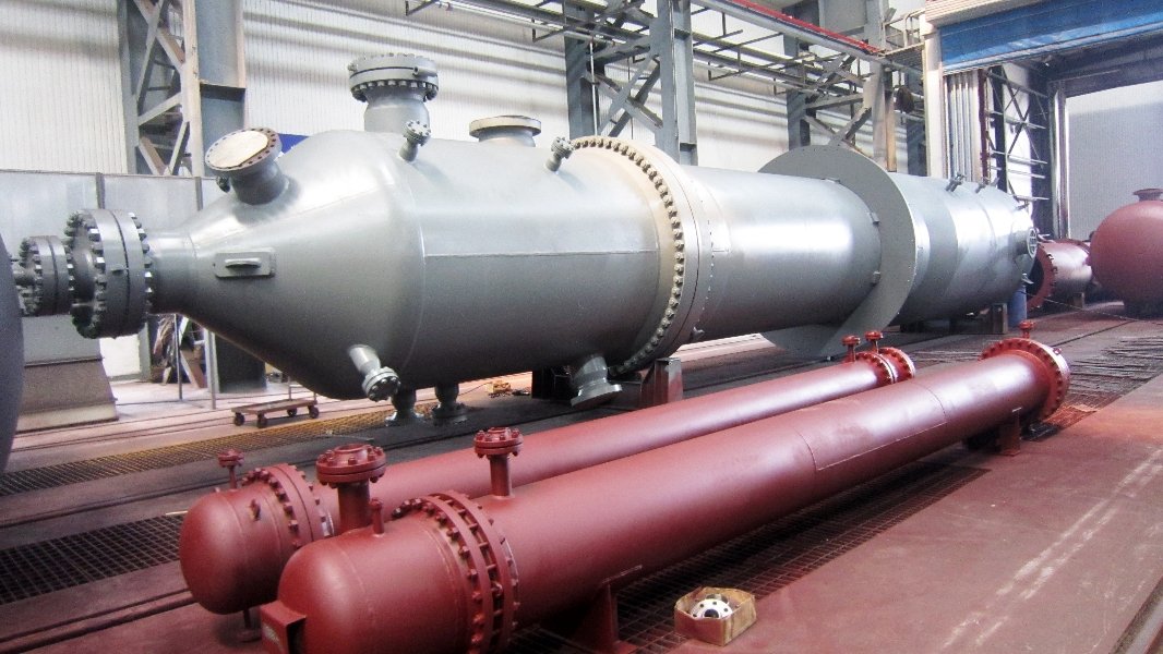
Make the Nozzle-Load Schedule Unambiguous
Provide a traceable load set for each connection and relevant case. Six numbers without their coordinate system, units and application point are not a complete input.
The following is an illustrative field checklist for project discussion, not a completed engineering datasheet. Populate it from the approved project basis and analysis; no load values are implied.
| Field | Information to provide | Clarification to resolve |
|---|---|---|
| Equipment and connection | Vessel tag, nozzle tag, piping line and model node reference | Do the load schedule and arrangement drawing identify the same connection? |
| Case identification | Case ID, physical condition and combination definition | Is this a simultaneous case, a range or an envelope? |
| Force components | Signed Fx, Fy and Fz in the stated axes | Are these loads exerted by the pipe on the vessel, or the opposite reactions? |
| Moment components | Signed Mx, My and Mz about the stated axes | What defines positive rotation? |
| Units | Explicit force and moment units, such as N and N·m, or kN and kN·m | Are unit conversions documented and consistent? |
| Coordinate definition | Axis sketch and mapping between plant, piping-model and local equipment axes | Which direction is positive for each axis? |
| Application point | Identified location on a referenced drawing, with any required offsets | Are the values at the flange face, shell junction or another model point? |
| Associated conditions | Relevant pressure, temperature and equipment condition for the case | Which conditions coincide with this load set? |
| Included load effects | Statement of what the exported reactions include, including the treatment of pressure thrust where relevant | Are the piping and equipment assessments using compatible assumptions without omitting or duplicating an effect? |
| Analysis assumptions | Relevant support arrangement, equipment movement and interface flexibility assumptions | What information must the equipment designer confirm? |
| Document control | Originator, analysis/drawing revisions, issue status and outstanding inputs | Is the information preliminary or accepted for the intended activity? |
Scroll the table horizontally to view all columns on smaller screens.
Fix the Coordinate System and Application Point
Do not assume that “X” means the same direction in the piping model and the vessel calculation. Require a sketch or an explicit axis mapping, including the convention for loads acting on the equipment. A reaction reported for the opposite side of the interface needs interpretation before use.
Changing the reporting point can also change the moment associated with an applied force. The responsible engineer should handle any required transformation, retain its basis and state where the final values apply. Renaming a table heading from “flange face” to “shell junction” is not that transformation.
PVEng’s Sample Vessel 8 report, dated April 26, 2007, explicitly identifies global coordinates, the input location and loads translated to the model application point. It illustrates why these definitions matter; its historical software settings and numerical results are not design inputs for another vessel.
Keep Load Cases and Simultaneous Components Together
Request the cases required by the project design basis, with the components that belong together. A table labelled only “maximum nozzle loads” leaves the equipment designer to guess what the values represent.
Ask the engineering team to identify the applicable conditions, rather than treating the following discussion list as a mandatory combination schedule:
- Operating conditions: The relevant operating states, including different temperatures, inventories or equipment movements where these affect the piping reactions.
- Installation, testing and shutdown conditions: Whether connected piping imposes loads in these states, and what support and equipment conditions apply.
- Occasional or transient conditions: Relevant environmental or process events identified by the project. Specify the required analysis basis; do not automatically apply offshore motion requirements to an onshore vessel.
- Repeated loading: Whether ranges, cycles or additional histories are needed for the assigned assessment, rather than assuming a static maximum describes repeated service.
Keep case definitions attached to the exported results. PVEng’s spring-hanger piping analysis example reports operating, occasional and expansion-related outputs separately. This is useful evidence that result categories need context, not a set of combinations to copy into every purchase specification.
Do Not Turn an Envelope into an Operating Case
An envelope can summarize extremes for screening, but it should remain labelled as an envelope. The largest value of each component may come from a different case and may not occur at the same time.
Hypothetical example: The largest axial force occurs during one operating state, while the largest bending moment occurs during another. Placing both maxima in one row does not demonstrate that the row represents an actual simultaneous condition. Nor does calling it “conservative” explain how it should be assessed.
Ask the responsible engineers to agree whether to use case-by-case loads, an explicitly defined design envelope, or another justified approach. Preserve the source case IDs, signs and combination rules. For assessments involving several connections, clarify which nozzle load sets act together across the vessel; maxima selected independently at each connection can create another artificial combination.
Compare Actual and Allowable Loads on the Same Basis
Actual piping loads describe the demand calculated for the stated piping model and cases. Allowable equipment loads describe limits established for a defined equipment design and assessment basis. Neither should be treated as a context-free list of numbers.
Before accepting a comparison, work through these checks:
- Match the interface. Confirm the equipment tag, connection, drawing revision, axes, signs, units and reporting point. Resolve any required conversion before comparing values.
- Match the conditions. Identify the pressure, temperature, geometry and other assumptions behind the allowable-load statement and whether they cover the proposed case.
- Read the interaction rules. Establish whether each limit applies individually, to a specified simultaneous set, or through a stated combined-load assessment. Passing separate component comparisons is sufficient only where the accepted assessment basis permits that conclusion.
- Record the engineering disposition. Request acceptance, rejection or a defined need for further evaluation against the submitted load revision. Keep qualifications attached to the result.
The distinction in step 3 is visible in PVEng’s 2007 sample report: its allowable-load section separates individual from simultaneous limits, with notes restricting the individual values to the absence of other listed components. The procurement lesson is to read the conditions behind a limit, not to reuse that report’s values or calculation approach.
If a project specifies provisional loads before final piping analysis, label them as an agreed design requirement or assumption. They do not become calculated actual piping reactions simply because they appear on a purchase order. Identify who will reconcile the final analysis with the basis used for the equipment design.
When a submitted load exceeds an agreed limit, obtain an engineering disposition. The response may involve revised piping arrangements, revised equipment design or a further justified assessment. Procurement should coordinate the decision and its document consequences, rather than selecting an unverified larger allowable value.
Define the Scope of the Complete Vessel Assessment
A local nozzle check answers a defined local question. It should not be presented as acceptance of every structural requirement of the complete vessel.
Ask the equipment designer to state which applicable checks are included and where the remaining responsibilities sit:
- The nozzle-to-shell or nozzle-to-head region and the assumptions used to represent it.
- The connection assembly, including any required flange assessment.
- The vessel as a whole, including the effect of relevant combinations of loads at different connections.
- Supports and the information passed to the supporting structure or foundation designer.
- Any additional assessment required by cyclic, dynamic or other project-specific service conditions.
ABSA’s AB-381k guideline discusses local attachment analysis and flange assessment separately, and emphasizes the applicability of the chosen methods. Its Alberta registration context should remain distinct from the requirements governing a project elsewhere.
Also distinguish piping-model assumptions from vessel verification. Bentley’s nozzle-flexibility guidance describes using reactions from the piping analysis in a separate nozzle/vessel assessment. A piping model can represent the interface without completing every equipment check. Record any agreed flexibility or movement data passed between the disciplines, including revisions that could affect the calculated reactions.
For the broader scope, Bentley’s AutoPIPE Vessel description lists local-load, support and full-vessel analyses as distinct capabilities. This illustrates the range of assessment tasks; it does not establish that a particular software package is mandatory or that a supplier has performed those tasks.
Request the governing method and edition, its applicability to the actual geometry, the cases assessed and the limits of the conclusion. A statement that “FEA was used” or “the nozzle passed” is incomplete without that scope. This article does not select a calculation method or determine structural adequacy for any vessel.
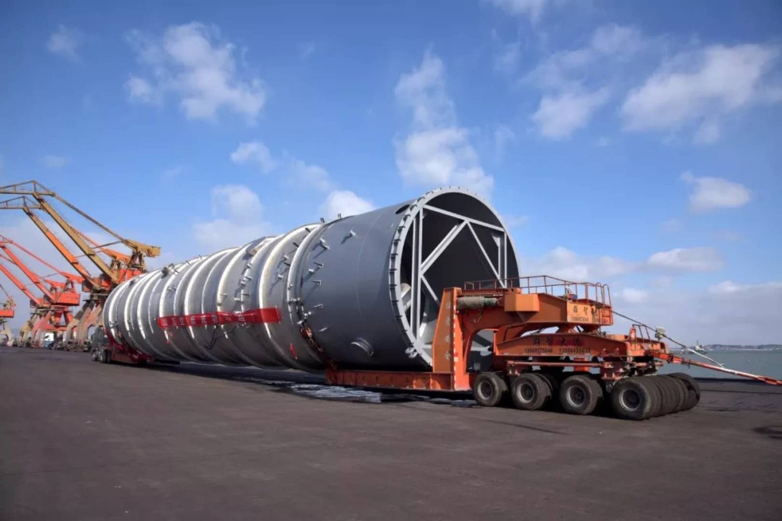
Close the Interface Before Releasing Affected Work
Identify who supplies the piping loads, who establishes or confirms equipment limits, who performs the vessel assessment and who accepts the interface for the next activity. These assignments belong in the project arrangements; a commercial allocation does not remove duties imposed by the applicable code or jurisdiction.
A practical starting allocation is for the piping stress team to issue the calculated reactions and model assumptions, and for the assigned vessel designer to confirm the equipment assessment and any allowable-load statement. The owner or EPC should identify the coordinator and authorized reviewer. Confirm these assignments in the actual scope rather than assuming that every calculation is included in the fabricator’s quotation.
For discussion, use the following deliverables at successive procurement stages. This is a suggested coordination framework, not a universal approval procedure.
| Stage | Load-related deliverable | Decision to record |
|---|---|---|
| Inquiry and quotation | Available load schedule, geometry, design basis and a visible list of missing inputs | What assumptions support the offer, and which engineering tasks are included? |
| Design coordination | Checked case-based loads or an agreed envelope, equipment assessment and resolved interface comments | Are the submitted loads accepted for the identified design and conditions? |
| Release of affected work | Authorized input revisions, assessment references and closure of relevant open items | Which work is permitted, by whom, and on which documented basis? |
Scroll the table horizontally to view all columns on smaller screens.
Do not silently convert an unresolved input into zero load. If final piping results are unavailable, document the proposed interim basis, its approval route and the activity it can support. An estimate prepared against preliminary information should remain distinguishable from permission to fabricate affected parts of the vessel.
When piping routing, supports, equipment movement or connection geometry changes, ask the responsible engineers whether the load schedule and vessel assessment need revision. A changed sign, reporting point or model assumption can also require reconciliation even when a summary force magnitude appears unchanged.
Keep the original submission, revised load set, engineering disposition and affected drawing revisions linked by equipment tag. Before restarting or releasing affected work, confirm that the relevant reviewers have accepted the current basis. Retain the accepted load schedule and assessment references in the agreed final documentation package so later changes can be compared with what was actually evaluated.
FAQ
Should an unknown nozzle-load component be entered as zero?
No. Use a clearly defined pending status when the input is unknown. Zero should mean that the responsible originator has established that value for the stated case, not that the field has yet to be completed. Explain the status convention in the load schedule.
Can buyers request a quotation before final piping loads are available?
Yes, provided the offer clearly identifies its provisional basis and outstanding inputs. Ask which changes could require design or commercial review and which activities remain dependent on final engineering acceptance. A preliminary quotation is not evidence that the eventual piping loads are acceptable.
Does a flange pressure class establish allowable external piping loads?
No. Do not treat the pressure class alone as an external-load acceptance statement. ABSA’s external-loadings guideline explicitly addresses flange evaluation under external loading. Request the assessment applicable to the proposed connection, loading and project requirements rather than inferring acceptance from the class designation.
Include the Load Basis in the Vessel Inquiry
For custom pressure vessels, issue the equipment datasheet, nozzle-orientation drawing, piping-load schedule and applicable design basis together. Identify unresolved inputs and ask the responsible engineering parties to confirm the assessment scope and acceptance route.
To discuss the complete vessel scope with WSHI, share the available documents and their revision status. Request confirmation of the manufacturing and documentation scope, including any separately assigned engineering work. The objective is an agreed interface for a complete industrial vessel, with load acceptance supported by the appropriate project assessment.
References
Sources reviewed on October 12, 2026. The ABSA document is jurisdiction-specific guidance; the PVEng report is a historical example. Neither supplies generic load limits for this article. Referenced code texts were not independently reviewed in full.
- ABSA. Guideline for Design Registration of Pressure Vessels with External Loadings. AB-381k, December 2025; especially the scope and external-load assessment sections.
- Pressure Vessel Engineering. FEA Component Report — Sample Vessel 8, Nozzle A. April 26, 2007; Nozzle/Pro 6.0. Load-input definitions on PDF page 9 and allowable-load notes on pages 16–17.
- Pressure Vessel Engineering. Piping System With Spring Hanger Stress Analysis. Undated web page; operating, occasional and expansion result descriptions.
- Bentley Technical Support Group. 09. Nozzle Flexibility in AutoPIPE and AutoPIPE Nozzle. Logged July 2015; page identifies version 09.06.02.06. Used for the piping-to-equipment analysis distinction.
- Bentley Systems. AutoPIPE Vessel. Undated product overview; used to distinguish local, support and full-vessel assessment scopes.