Installing a double pipe heat exchanger looks straightforward because the equipment is compact and the flow path is easy to understand. In practice, poor installation can cause nozzle stress, flange leakage, vibration, trapped air, debris-related fouling, excessive pressure drop, thermal shock, difficult maintenance, and unsafe startup. A properly fabricated exchanger can still perform poorly if the site team ignores support design, piping flexibility, venting, draining, flushing, testing, or commissioning discipline.
The proper installation of a double pipe heat exchanger should include document review, delivery inspection, foundation and support preparation, safe lifting, correct orientation, stress-free piping connection, installation of valves and instruments, venting, draining, flushing, leak or pressure testing, insulation where required, controlled startup, and final performance checks. The unit should be installed according to the approved drawings, manufacturer instructions, project specifications, and applicable pressure equipment or piping requirements.
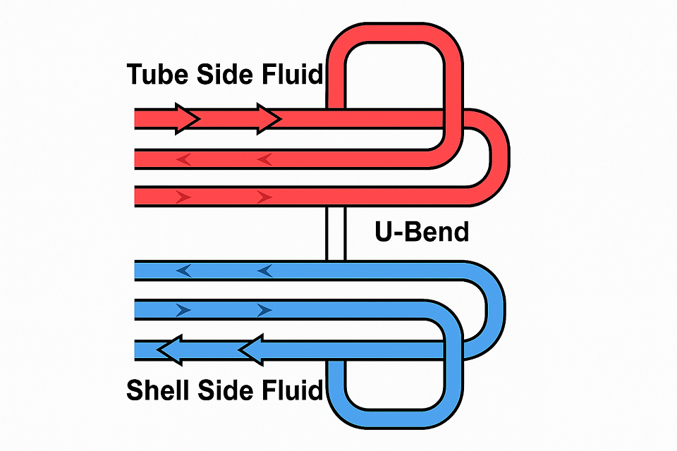
For equipment category planning, buyers can compare hairpin heat exchangers, broader industrial heat exchangers, shell and tube heat exchangers, and other custom pressure vessels before finalizing the project equipment list.
Proper double pipe heat exchanger installation is more than connecting two pipe nozzles.True
The installation must also address support loads, nozzle alignment, thermal expansion, venting, draining, flushing, leak testing, instrumentation, maintenance access, and controlled startup.
A double pipe heat exchanger can be pulled into alignment with flange bolts if the piping is slightly off.False
Using flange bolts to force alignment can distort gasket faces, overload nozzles, damage supports, and create leakage or fatigue risk.
1. Review Drawings, Datasheets, and Installation Requirements
The first step is document control. Before the exchanger is moved into position, the installation team should review the approved general arrangement drawing, nozzle orientation drawing, support drawing, lifting drawing, datasheet, nameplate data, gasket and bolting list, pressure test requirements, operating manual, and inspection plan. If the exchanger is supplied as a skid or multiple hairpin sections, the field assembly sequence and tag numbers should also be confirmed.
Double pipe exchangers may be supplied as simple concentric pipe units, removable hairpin exchangers, multitube hairpin exchangers, high-pressure process exchangers, or exchanger banks. Each arrangement has different requirements for lifting, support, cleaning access, flow direction, venting, draining, and maintenance clearance.
| Document to review | What to confirm | Risk if ignored |
|---|---|---|
| General arrangement drawing | Overall length, nozzle size, nozzle orientation, support points, maintenance clearance | Wrong placement, piping rework, blocked maintenance access |
| Datasheet and nameplate | Design pressure, design temperature, service fluid, flow direction, allowable limits | Operation outside design conditions |
| Foundation or support drawing | Anchor bolts, sliding supports, pipe shoes, saddle locations, elevation | Thermal stress, vibration, support settlement |
| Lifting information | Weight, center of gravity, approved lifting points, sling angles | Unsafe handling or equipment damage |
| Gasket and bolting list | Correct gasket material, bolt grade, lubricant, tightening method | Flange leakage or joint failure |
| Test package | Hydrotest or leak-test boundary, test pressure, blinds, hold points | Unsafe or incomplete commissioning |
The TEMA standards are widely used as a reference for shell and tube heat exchanger mechanical design and include installation, operation, and maintenance guidance in the standards framework. For pressure equipment, ASME BPVC Section VIII Division 1 is commonly referenced where the exchanger falls within pressure vessel construction requirements. The applicable code basis should be confirmed by project engineers and the inspection authority.
2. Inspect the Exchanger After Delivery
Before installation, inspect the exchanger for shipping damage, missing parts, flange-face damage, coating damage, bent supports, missing nameplates, damaged vents or drains, loose plugs, missing gasket kits, and foreign material inside the connections. Flange protectors should normally remain in place until the piping is ready for final connection.
Check the equipment tag, drawing revision, flow arrows, connection size, pressure rating, and material markings against the purchase order. If damage is found, record it with photos before moving the unit. A small dent, scratched gasket surface, contaminated passage, or missing drain plug can become a startup problem later.
3. Prepare Foundation, Supports, and Maintenance Space
The exchanger should be installed on the support arrangement shown on the approved drawing. The foundation or structural steel should be level, clean, and ready for anchor bolts, saddles, pipe shoes, guides, or sliding supports. If one end is designed to slide during thermal expansion, it should not be accidentally fixed during installation.
Maintenance clearance is especially important for hairpin and removable-bend designs. Leave room for flange access, return bend removal, cleaning, pressure testing, insulation removal, and future replacement. A compact exchanger placed in a crowded pipe rack may save space during installation but create long shutdowns during maintenance.
| Site preparation item | Required check | Why it matters |
|---|---|---|
| Foundation level | Confirm elevation, flatness, grout condition, and anchor position | Prevents twisting and poor flange alignment |
| Fixed and sliding supports | Verify which support is anchored and which is allowed to move | Allows thermal expansion without overstressing the exchanger |
| Nearby pipe supports | Install before final pipe connection | Prevents exchanger nozzles from carrying pipe weight |
| Return bend access | Keep clear space for removal, inspection, and gasket replacement | Reduces future maintenance time |
| Vent and drain access | Make sure operators can reach valves and plugs safely | Supports proper filling, draining, and startup |
| Insulation space | Allow for insulation thickness and removable covers | Prevents access conflicts after insulation is installed |
4. Lift and Position the Exchanger Safely
Lift the exchanger only from approved lifting points or according to the manufacturer lifting drawing. Do not lift from nozzles, vents, drains, instrument connections, return bends, or unapproved piping. Use soft protection where slings may contact coated or stainless surfaces. If the exchanger is long or unbalanced, use tag lines and a lifting plan that accounts for center of gravity.
After setting the exchanger, confirm that it is level and square, bearing properly on its supports, and positioned according to the required flow direction. Check that the nozzle orientation matches the piping drawing before bolting any pipework. It is much easier to correct orientation before final piping fit-up than after the lines are welded and supported.
5. Connect Piping Without Nozzle Strain
Piping connection is one of the most important installation steps. The connected piping should be independently supported and naturally aligned. The exchanger nozzles should not be used to pull piping into place, carry valve weight, correct spool errors, or restrain thermal expansion. Poor alignment can damage gaskets, distort flanges, overload welds, and create leakage during startup.
For hot service, thermal movement should be reviewed before final bolting. Expansion loops, guides, anchors, sliding supports, or expansion joints may be required depending on the piping design. Heavy valves, strainers, control valves, and instruments should be separately supported where needed.
| Piping check | Good installation practice | Warning sign |
|---|---|---|
| Flange fit-up | Flanges meet naturally and evenly | Bolts are used to pull flanges together |
| Bolt-hole alignment | Pipe spool and support adjustment provide alignment | Bolts are forced through misaligned holes |
| Pipe dead weight | Pipe supports carry pipe, valves, and insulation loads | Nozzles support nearby pipe or valve weight |
| Thermal expansion | Guides, anchors, loops, or sliding supports are confirmed | Both exchanger and piping are rigidly locked |
| Vibration | Supports and restraints match service conditions | Long unsupported runs or loose supports remain |
| Flow direction | Connections match nameplate, drawing, and process design | Field team assumes either direction is acceptable |
Piping stress control is one of the most important installation checks for double pipe heat exchangers.True
Even a compact exchanger can leak or suffer fatigue if connected piping transfers weight, vibration, misalignment, or thermal expansion forces into the exchanger connections.
6. Install Vents, Drains, Valves, Instruments, and Accessories
Vents and drains are not optional details. Vents help remove trapped air or non-condensables during filling and startup. Drains help remove test water, process liquid, condensate, cleaning solution, or residual fluid during shutdown. Missing or inaccessible vents and drains can make commissioning difficult and maintenance unsafe.
Typical accessories may include isolation valves, bypass valves, pressure gauges, temperature instruments, drain valves, vent valves, sample points, strainers, relief connections, insulation, heat tracing, and local supports. The final scope depends on the process design and project specification.
| Connection or accessory | Installation purpose | Buyer or site-team check |
|---|---|---|
| High-point vents | Remove trapped air and support filling | Accessible and correctly oriented |
| Low-point drains | Drain test water, condensate, or process fluid | Routed safely and not blocked by supports |
| Isolation valves | Allow maintenance or shutdown isolation | Installed on required sides and accessible |
| Temporary strainers | Catch weld slag, scale, and startup debris | Located where they can be inspected and removed |
| Temperature and pressure instruments | Monitor duty, pressure drop, and operating stability | Installed according to P&ID and calibrated where required |
| Insulation or tracing | Reduce heat loss, personnel exposure, freezing, or viscosity issues | Does not block flanges, vents, drains, or nameplate |
7. Flush, Clean, and Protect the System Before Startup
New piping can contain welding slag, grinding dust, scale, oil, dirt, gasket pieces, and construction debris. If this material enters a double pipe exchanger, it can block passages, reduce heat transfer, erode surfaces, damage tubes, and raise pressure drop. The connected lines should be cleaned or flushed according to the commissioning procedure before the exchanger is placed into normal service.
For water-sensitive, corrosion-sensitive, or high-purity service, drying, chemical cleaning, passivation, nitrogen blowing, or special cleanliness requirements may be required. Temporary strainers should be checked after initial circulation and removed or replaced according to the startup plan.
8. Perform Leak Testing or Pressure Testing
Testing should follow the approved project procedure, applicable code, manufacturer guidance, and site safety rules. Depending on the service and equipment design, testing may include hydrostatic testing, pneumatic leak testing, gasket leak checks, flange inspection, pressure-hold checks, or system leak testing after piping installation.
If the exchanger is insulated, complete required leak checks before final insulation wherever possible. Any leakage at flanges, vents, drains, plugs, threaded joints, or return bends should be corrected before startup. Pressure testing should also consider temporary supports, test water weight, blind locations, drain path, relief protection, and drying after test completion.
9. Start Up the Exchanger Gradually
Startup should be controlled and gradual. Operators should verify that supports are secure, vents and drains are functional, instruments are active, valves are in the correct position, temporary blinds are removed, and the system has been flushed and tested. In many installations, the cold stream is introduced first with vents open until air is removed. The hot stream is then introduced slowly to reduce thermal shock and differential expansion.
During startup, monitor pressure, temperature, pressure drop, flow stability, vibration, abnormal noise, flange leakage, support movement, and outlet temperature. Avoid sudden valve opening, water hammer, pump deadheading, and rapid temperature swings. If abnormal vibration or leakage appears, stop and investigate before moving to full operation.
| Startup step | What to do | What to monitor |
|---|---|---|
| Pre-start check | Confirm installation, supports, valves, instruments, vents, drains, and test status | Open items, missing plugs, blocked access |
| Initial filling | Fill slowly and vent trapped air | Air pockets, leaks, unstable pressure |
| Cold-side circulation | Establish stable flow before adding heat where applicable | Pressure drop, flow direction, vibration |
| Hot-side introduction | Introduce hot fluid gradually | Thermal movement, flange leakage, outlet temperature |
| Stepwise loading | Increase to normal operating rate in controlled steps | Temperature approach, pressure drop, abnormal noise |
| Post-start inspection | Check supports, bolting, insulation, drains, and instruments | Movement, seepage, support looseness |
10. Handover Documentation and Maintenance Planning
After successful installation and startup, the site team should compile the installation and commissioning records. These may include final drawings, inspection records, torque or tensioning records, pressure test reports, leak test reports, flushing records, temporary strainer inspection records, insulation records, punch-list closure, and startup observations.
Maintenance planning should identify cleaning method, gasket replacement strategy, spare parts, inspection frequency, access requirements, and shutdown procedure. A double pipe exchanger often has simpler geometry than larger shell and tube equipment, but it still needs clear maintenance access and reliable documentation.
For buyers comparing procurement and lifecycle decisions, the earlier article on double pipe heat exchanger cost considerations can help connect installation choices with total cost, pressure drop, materials, cleaning access, inspection scope, and maintenance planning.
Common Installation Mistakes to Avoid
| Mistake | Possible result | Better practice |
|---|---|---|
| Ignoring approved drawings | Wrong orientation, blocked access, piping rework | Use controlled drawings and check revision numbers |
| Forcing pipe alignment | Nozzle stress, gasket distortion, leakage | Adjust pipe supports and spool fit-up before bolting |
| Fixing both ends of a hot exchanger | Thermal stress and support damage | Confirm fixed and sliding support functions |
| Removing flange covers too early | Dirt, moisture, or surface damage | Keep covers installed until final connection |
| Skipping flushing | Fouling, blockage, erosion, pressure drop | Flush or clean lines before startup |
| Starting the hot side too quickly | Thermal shock, leakage, differential expansion | Use gradual startup and monitor temperature changes |
| Insulating before leak checks | Hidden leaks and difficult repairs | Complete required testing before final insulation |
What Buyers Should Prepare Before Installation
Before installing a double pipe heat exchanger, buyers and EPC teams should prepare the approved drawings, datasheet, nameplate information, lifting plan, foundation readiness report, piping isometrics, pipe stress notes, gasket and bolting list, valve and instrument list, flushing plan, pressure test procedure, insulation specification, startup procedure, and final documentation requirements.
For petroleum, petrochemical, and natural gas projects, buyer specifications may reference documents such as API Standard 660 or IOGP S-614 where shell and tube heat exchanger procurement requirements apply. For thermal background, MIT’s heat exchanger notes explain common flow arrangements and counterflow heat transfer concepts. Project-specific installation rules should still govern the final procedure.
FAQ
What are the basic steps for installing a double pipe heat exchanger?
The basic steps are reviewing drawings and datasheets, inspecting the equipment after delivery, preparing supports and foundation, lifting and positioning the exchanger safely, confirming orientation and maintenance clearance, connecting piping without nozzle strain, installing vents and drains, flushing the system, performing leak or pressure testing, starting up gradually, and checking performance after startup.
How should piping be connected to a double pipe heat exchanger?
Piping should be connected only after the exchanger is level, supported, and aligned. Pipework should be independently supported and should not force the exchanger nozzles into alignment. The installation should account for pipe weight, vibration, thermal expansion, flange cleanliness, gasket selection, and bolt tightening sequence.
Why are vents and drains important?
Vents remove trapped air and non-condensables during filling and startup. Drains remove test water, condensate, cleaning liquid, or process fluid during shutdown and maintenance. Missing or inaccessible vents and drains can create startup instability, corrosion risk, or unsafe maintenance conditions.
Should the cold side or hot side be started first?
Many procedures introduce the cold stream first, then gradually introduce the hot stream to reduce thermal shock. The final startup sequence should follow the manufacturer instructions, process design, and site operating procedure.
What installation mistakes should be avoided?
Common mistakes include forcing misaligned piping, omitting pipe supports, blocking maintenance access, fixing sliding supports, removing flange covers too early, skipping flushing, insulating before leak checks, using the wrong gasket, and starting the exchanger with rapid temperature or pressure changes.
Can a double pipe heat exchanger be installed outdoors?
Yes, if the equipment design, coating, insulation, tracing, supports, materials, vents, drains, and weather protection match the service environment. Outdoor installation should consider rain, freezing, solar exposure, corrosion, access, and long-term maintenance.
Conclusion
Proper installation of a double pipe heat exchanger requires more than setting the unit in place and connecting two process lines. The installation must protect the exchanger from nozzle strain, thermal stress, vibration, trapped air, debris, leakage, and poor maintenance access. A structured approach helps EPC teams and plant owners reduce commissioning risk and improve long-term reliability.
If you are sourcing double pipe heat exchangers, hairpin heat exchangers, shell and tube heat exchangers, pressure vessels, separators, towers, or other custom process equipment for chemical, petrochemical, refinery, energy, or EPC projects, you can discuss your project requirements with an engineering and manufacturing team. Sharing datasheets, drawings, installation conditions, materials, inspection needs, and delivery terms will support accurate quotation, fabrication, and site coordination.