
A pressure vessel can pass its required hydrostatic or pneumatic pressure test without automatically demonstrating compliance with a separate leakage-rate requirement. For EPC buyers, confusing these two acceptance objectives can leave important gaps in equipment specifications and final inspection records.
Pressure testing verifies compliance with the applicable pressure-boundary test requirements, while a separate leak-tightness test verifies leakage against a defined detection or leakage-rate criterion. Buyers should specify the governing code, test boundary, medium, pressure difference, temperature conditions, detection method, acceptance criterion, and required records, rather than assuming that passing a pressure test proves zero leakage under every operating condition.
The necessary verification depends on the vessel service, final assembly, test method and project requirements. Hydrostatic and pneumatic tests remain important construction checks, but their results must be interpreted within the actual examination scope.
What Do Pressure Tests and Leak-Tightness Tests Actually Demonstrate?
Pressure testing and leak-tightness testing can involve the same pressure boundary, but they do not necessarily demonstrate the same acceptance condition.
A pressure test evaluates a vessel against the applicable construction-code or project pressure-test requirements. Depending on the governing procedure, the examination may also include checking for visible leakage. A separate leak-tightness test addresses whether leakage through the specified boundary is detectable or remains within a defined acceptance criterion under agreed test conditions.
The distinction is important because passing a construction-code pressure test does not automatically establish compliance with a separately specified leakage-rate limit or with every future operating condition.
Hydrostatic and Pneumatic Pressure Tests
Hydrostatic and pneumatic tests are two ways of conducting pressure-integrity verification. They differ primarily in the test medium and associated hazards, not simply in whether leakage can be detected.
| Test or verification activity | Main objective | What a satisfactory result does not automatically establish |
|---|---|---|
| Hydrostatic pressure test | Demonstrate compliance with applicable liquid-pressure test requirements, including relevant visual examinations | A quantified gas leakage rate or tightness after later assembly changes |
| Pneumatic pressure test | Demonstrate compliance with applicable gas-pressure test requirements and associated examination | Compliance with a separate high-sensitivity leakage criterion |
| Local leak-detection examination | Identify leakage at specified joints, welds, closures or other examination areas | Total equipment leakage rate unless the method and procedure support that claim |
| Quantitative leak-tightness test | Evaluate leakage against an agreed measurable criterion | Structural pressure-test compliance unless separately established |
Editorial comparison for pressure-vessel procurement, not a replacement for the governing construction code.
Hydrostatic testing commonly uses water or another approved liquid. Pneumatic testing uses a compressible gas and introduces substantially greater stored-energy hazards, requiring appropriate engineering justification and safety controls. The applicable method and test conditions should follow the construction code, vessel design and approved procedure.
ASME BPVC Section VIII Division 1 addresses pressure-vessel design, fabrication, inspection and testing, while ASME Section V covers nondestructive examination methods, including leak testing. These are related requirements but should not be treated as interchangeable certifications of every possible leakage condition. (ASME Section VIII Division 1; ASME Section V Overview)
Visible Leakage Is Not the Same as a Specified Leak Rate
A pressure examination may establish that no visible liquid leakage or detectable gas leakage was found using its prescribed method.
That is a meaningful result within the defined test scope. It should not be restated as “zero leakage under all operating conditions.”
A leakage-rate requirement answers a more specific question: how much leakage, if any, is permitted under a defined set of conditions, and how will compliance be demonstrated?
The American Society for Nondestructive Testing (ASNT) distinguishes leak-detection methods and explains that leakage rate depends on both the leakage path and test conditions.
Before accepting a supplier’s statement that a vessel is “leak-free,” the buyer should therefore ask which boundary, method, pressure condition and acceptance criterion support that statement.
When Should Buyers Specify a Separate Leak-Tightness Requirement?
A separate leak-tightness requirement becomes relevant when the vessel’s intended service, completed assembly or contractual acceptance needs cannot be adequately demonstrated by the prescribed construction pressure test alone.
This does not mean every vessel requires an additional helium test or a universal leakage limit. The buyer should first establish what must remain tight, under which conditions, and why the existing test evidence may be insufficient.
Consider the Actual Service and Acceptance Objective
Additional requirements may be appropriate for equipment involving:
- Process fluids for which uncontrolled external leakage would create significant safety, environmental, contamination or product-quality concerns.
- Vacuum service where air ingress can affect process operation.
- Gas containment where the project specifies a measurable leakage criterion.
- Multiple pressure compartments where cross-leakage between circuits is a distinct concern.
- Removable closures, gasketed joints, instrumentation connections or other interfaces that may be completed or disturbed after the shop pressure test.
The decision should follow the actual service conditions, risk assessment, applicable standards and project specification.
For example, a process vessel required to maintain vacuum may need a tightness assessment based on inward leakage. A vessel intended to contain a pressurized gas may need an outward-leakage criterion. The pressure direction and relevant leakage paths differ.
Neither scenario establishes a universal test method or acceptable leakage rate.
Separate the Vessel Boundary From the Final Assembly
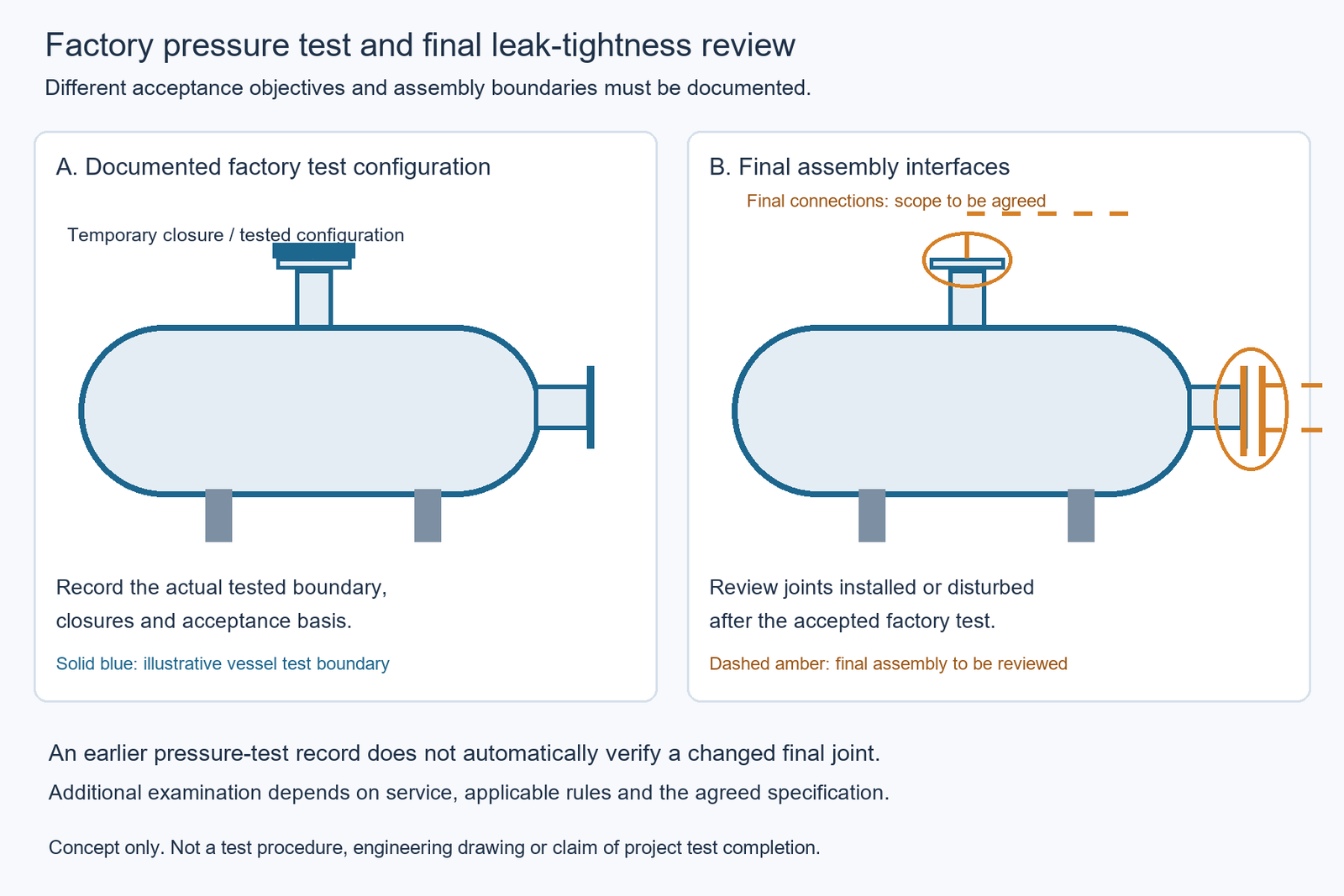
A factory hydrostatic test may be performed before all final connections are installed or before certain temporary closures are replaced with operating components.
If a joint is assembled or disturbed after the accepted pressure test, the earlier test record may not demonstrate the tightness of that final configuration.
The purchaser should identify whether the additional requirement applies to the factory vessel, a particular connection, a completed equipment package, or another agreed test boundary.
Consider Equipment With More Than One Pressure Circuit
A shell-and-tube heat exchanger is a useful example because the shell side and tube side have separate pressure boundaries.
Depending on its configuration, the buyer may need to distinguish external leakage from leakage between the two circuits. An acceptable result for one circuit does not necessarily demonstrate that all internal interfaces have been adequately assessed.
Any proposed examination must also respect the differential-pressure limitations of the actual equipment.
The purpose is to specify the leakage question and responsible test boundary—not to provide a generic pressurization sequence.
How Should Leakage Acceptance Criteria and Test Conditions Be Defined?
A meaningful leak-tightness specification must describe both the acceptance criterion and the conditions under which compliance will be assessed.
Writing “leak test required” on a pressure-vessel datasheet is not enough. Even “no leakage permitted” can be ambiguous if the document does not state the detection method, examination boundary and required sensitivity.
Define the Acceptance Basis
A purchaser may specify a qualitative condition, such as no detectable leakage by a defined examination method, or a quantitative maximum leakage rate.
These are different forms of acceptance.
A qualitative requirement is tied to the selected method and observation conditions. A quantitative requirement needs a measurable leakage-rate definition, including its units and applicable reference conditions.
The Pfeiffer Vacuum leak-detection guidance emphasizes defining the required tightness before choosing a detection method. Its discussion also highlights the importance of selecting an appropriate measurement approach and units.
Identify the Required Specification Fields
| Specification field | What the buyer should establish | Why it matters |
|---|---|---|
| Acceptance objective | Qualitative leak detection or quantitative leakage-rate verification | Determines the evidence needed for acceptance |
| Equipment boundary | Complete vessel, specified compartment, joint group or final assembly | Identifies what the result covers |
| Test medium | Approved liquid, gas or tracer medium where applicable | Leakage behavior and detector suitability depend on the medium |
| Pressure conditions | Defined test pressure or differential-pressure condition, consistent with the approved basis | Leakage depends on the driving pressure difference |
| Temperature conditions | Relevant test temperature and any required stabilization or compensation | Affects fluid properties and measured pressure |
| Test configuration | Applicable closures, connected equipment, isolation points and temporary arrangements | Establishes whether the final service boundary is represented |
| Method and capability | Selected detection method, relevant sensitivity and measurement limitations | Determines what can reliably be demonstrated |
| Observation conditions | Required examination or measurement duration and applicable stability conditions | Makes results comparable and interpretable |
| Acceptance criterion | Defined detection condition or maximum leakage rate, including units where applicable | Prevents subjective interpretation |
| Verification responsibility | Supplier, purchaser, EPC and appointed inspection-party involvement | Establishes responsibility for review and acceptance |
Editorial purchasing template. Values and requirements must be established by the actual project.
Not all fields need to be repeated in every drawing. They may be distributed among the equipment datasheet, purchase specification, approved test procedure and Inspection and Test Plan (ITP). They must nevertheless be consistent and traceable.
Specify the Leakage Rate Without Inventing a Universal Limit
A quantitative leakage criterion should identify what is being measured, its unit and the relevant reference conditions.
Depending on the measurement approach, reporting may use pressure-volume flow units, standardized volumetric-flow units or another defined basis. These representations should not be compared without the necessary conditions and conversion information.
Leakage rate also depends on the gas or liquid properties and the pressure difference across the leakage path. A result obtained with a tracer gas under one test condition should not automatically be presented as the leakage rate of a different operating medium.
ISO 20484:2017 provides terminology for leak testing, while ISO 20485:2017 addresses tracer-gas detection methods. Their public descriptions establish the general scope of these standards, not a universal permissible leakage rate for every pressure vessel. (ISO 20484; ISO 20485)
The buyer should define the required performance and test basis together with the responsible process and inspection engineers. The equipment manufacturer can then confirm whether the requirement is technically and contractually within the proposed scope.
Which Leak-Detection Method Is Appropriate for the Required Evidence?
Leak-detection methods differ in the type of evidence they provide, the leakage they can detect and the conditions under which their results are meaningful.
A buyer should select or approve a method based on the required acceptance objective, rather than assuming that a more complex technique is always necessary or that any observed pressure change establishes leakage.
Compare the Main Detection Approaches
| Method | Evidence it can provide | Main limitation for buyer review |
|---|---|---|
| Visual leakage examination during an applicable pressure test | Visible evidence of liquid leakage or other detectable indications under the test conditions | Does not establish a separately specified low leakage-rate limit |
| Bubble-emission examination | Location of leakage producing observable bubble indications | Generally a qualitative location method, not a direct measurement of total leakage rate |
| Pressure-decay or pressure-rise assessment | Pressure change over a defined period, potentially supporting a leakage estimate with an appropriate model | Temperature, volume changes, gas effects and other influences must be addressed |
| Tracer-gas detection | Detection of tracer gas passing through leakage paths; qualitative or quantitative information depending on the technique | Requires suitable method, detector, test arrangement, calibration and reporting basis |
Editorial method comparison. Availability and suitability must be confirmed for the actual project.
Bubble Examination: Detection Is Not Quantification
Bubble-emission examination can help locate leakage at accessible surfaces under an appropriate differential-pressure condition.
ASTM E515-11(2022), Standard Practice for Leaks Using Bubble Emission Techniques, describes immersion and liquid-application approaches. Its official description states that the method is not intended to provide a quantitative measurement of total leakage rate. (ASTM E515-11(2022))
For an EPC buyer, a report stating “no bubbles observed” should therefore identify the inspected areas and examination conditions. It should not be converted into an unsupported numerical leakage-rate claim.
Pressure-Change Methods: Review the Measurement Basis
A pressure-decay method can provide information about gas loss from a closed test volume, while a pressure-rise method can be used in appropriate vacuum-related applications.
These methods require the reviewer to understand the defined volume, pressure measurements, time interval, temperature behavior and other relevant influences.
Leybold’s pressure-rise and pressure-drop guidance explains both approaches and identifies temperature effects as a potential limitation in large-volume pressure-decay testing.
A pressure change may support an acceptance decision when the method and conditions have been properly defined. The recorded change alone does not establish an unambiguous leakage rate.
Tracer-Gas Testing: Use the Required Sensitivity and Scope
Tracer-gas methods introduce or apply a detectable gas under an appropriate test arrangement and use a compatible detector to identify its passage through leakage paths.
The method may be used to locate individual leaks or assess leakage more broadly, depending on the technique and equipment.
ISO 20485:2017 describes leak-detection techniques using a tracer gas and a tracer-gas-specific detector. It does not establish that all industrial pressure vessels require a particular tracer gas or detection instrument. (ISO 20485:2017)
If the purchaser specifies a quantitative result, the proposed method must support the required measurement basis, including appropriate detector suitability, calibration, reference conditions and reporting.
A supplier’s access to an instrument does not, by itself, prove that the required acceptance criterion has been satisfied. The procedure, equipment capability and actual test result must correspond to the project requirement.
Why Is Pressure Drop Not the Same as Leakage Rate?
A pressure decrease recorded during an isolated test is not automatically equal to the vessel’s leakage rate.
Pressure is a measured state of the test system. Leakage rate describes the quantity of fluid passing through a leakage path over time under defined conditions. Relating one to the other requires additional information and a valid measurement model.
Pressure Changes Can Have More Than One Cause
For a gas-filled test system, pressure readings can be influenced by:
- Gas temperature changes during the measurement period.
- Effective test volume and its variation under pressure.
- Instrument resolution, uncertainty and measurement stability.
- Gas exchange through actual leakage paths.
- Other effects relevant to the particular system, such as condensation or gas release from surfaces.
The significance of each effect depends on the test arrangement.
For example, cooling of a confined gas can reduce its pressure even if no gas has escaped. A warming gas can partly offset a pressure decrease caused by actual leakage.
Leybold’s technical discussion of pressure-decay testing explicitly identifies temperature changes as a factor that may distort the interpretation of pressure measurements, particularly when testing large volumes. (Leybold)
Volume and Time Matter
A given pressure decrease can represent different amounts of gas loss in systems with different volumes.
Similarly, a pressure change measured over one period cannot automatically be compared with the same change measured over a much longer period.
Under appropriately controlled conditions, pressure-change data may be used in leakage calculations. However, the result depends on assumptions about volume, temperature, the gas and other relevant conditions.
This article does not provide a universal pressure-change conversion formula, because the applicable calculation and acceptance rules must correspond to the actual test arrangement.
What Should Buyers Check in a Pressure-Decay Report?
The reviewer should confirm that the report identifies:
- The equipment or test boundary and the defined test volume.
- Initial and final conditions, including the applicable pressure basis.
- The measurement period and relevant temperature information.
- Instrument identification and calibration or uncertainty information.
- The procedure used to distinguish relevant leakage from other influences.
- The agreed acceptance criterion and the actual result.
- Any exclusions or qualifications affecting interpretation.
If the specification accepts a maximum pressure decrease rather than a quantitative leakage rate, that criterion must still be associated with defined test conditions.
A pressure-decay acceptance requirement should not be presented as universally equivalent to a specified tracer-gas leakage rate.
What Should the ITP, Quotation and Final Acceptance Records Contain?
Pressure-test and leak-tightness requirements should be traceable from the purchasing specification to the approved Inspection and Test Plan, executed test records and final equipment acceptance.
A supplier’s quotation should make clear which tests are included, what each test demonstrates, and which additional requirements need confirmation or separate provision.
Connect the Purchase Requirement to the Evidence
| Procurement stage | Information to establish | Evidence expected |
|---|---|---|
| Equipment datasheet | Service, pressure boundaries, applicable design conditions and special tightness needs | Approved equipment requirements |
| Purchase specification | Governing code and edition, additional tightness criteria, method and required test conditions | Agreed technical specification |
| Supplier quotation | Included test scope, exclusions, proposed method and technical deviations | Traceable technical offer |
| Approved ITP | Test activities, reference documents, acceptance requirements and inspection participation | Approved inspection plan |
| Test procedure | Applicable equipment boundary, method, conditions, instruments and acceptance basis | Reviewed or approved procedure as required |
| Executed test record | Actual conditions, observations, measurements and pass/fail disposition | Signed or validated records under the project procedure |
| Final manufacturing dossier | Required reports, deviations, corrective actions, retests and release records | Complete acceptance documentation |
Editorial project-review matrix, not a prescribed regulatory form.
The governing construction code and the applicable project or regulatory requirements must be established before these documents are finalized.
Where an additional leakage criterion exceeds or differs from the normal construction pressure-test requirements, its technical and contractual basis should be agreed explicitly.
Clarify Supplier and Inspection Responsibilities
The equipment manufacturer should identify the pressure tests included in its contracted manufacturing scope and any proposed additional tightness examinations.
The process owner or responsible engineering team should define the operational tightness needs and any project-specific acceptance criterion.
The EPC contractor or purchasing engineer should reconcile these requirements with the equipment specification and proposed test scope. Independent inspection or certification-body participation should follow the actual contractual and regulatory requirements.
A requested tracer-gas method, for example, should not automatically be assumed to be included in the manufacturer’s normal pressure-test offering. The parties should confirm the method, capable service provider where required, acceptance basis, witnessing and documentation before placing the order.
Where a supplier proposes a different examination scope or acceptance basis, the difference should be documented through the project’s technical clarification or deviation process. See the pressure vessel quotation technical deviation guide for related procurement considerations.
Close Discrepancies Before Equipment Release
If a test result does not satisfy its acceptance criterion, the responsible team should document the finding and evaluate the cause and required disposition.
Depending on the issue, this may involve correcting an assembly condition, repairing a defect, reviewing a measurement problem, or performing additional examination and retesting under an approved procedure.
A subsequent satisfactory test does not, by itself, remove the need to record and close the original nonconformance.
Before release, buyers should confirm that all mandatory pressure-test requirements and agreed leak-tightness requirements have been satisfied or otherwise received an authorized disposition consistent with the governing rules.
For complete industrial pressure vessels and applicable pressure-rated industrial storage tanks, the enquiry should include the equipment datasheet, design and service conditions, applicable project standards, specified leakage criteria and required inspection documentation.
Frequently Asked Questions
What pressure should be used for a pressure vessel leak test?
There is no universal pressure that applies to every vessel leak test. The required pressure or differential pressure depends on the test objective, governing code, equipment design limits, selected method and project specification. The approved procedure should establish the applicable conditions without confusing a leak-tightness examination with a construction pressure test.
What is the allowable pressure drop in a leak test?
There is no universal allowable pressure drop. If pressure decay is the specified acceptance method, the criterion must identify the test conditions, measurement period, temperature considerations and applicable boundary. A permitted pressure change cannot automatically be treated as a universal leakage-rate limit.
How should a buyer verify that a pressure vessel has been properly tested?
The buyer should review the applicable construction pressure-test records and any separately specified leak-tightness evidence against the approved ITP and project requirements. Each record should identify the tested boundary, method, conditions, findings and acceptance disposition. The buyer should also confirm that relevant final assembly changes and unresolved nonconformances have been addressed.
Conclusion
A passed pressure test and an accepted leak-tightness test are related but not interchangeable forms of evidence. Buyers should define the required acceptance objective first, select a suitable method for that objective, and ensure the final records show exactly what was tested and accepted.
For a complete industrial pressure vessel enquiry, provide the equipment datasheet, design and operating conditions, service medium, governing requirements, any special tightness criteria and inspection expectations. These inputs allow the test scope and responsibilities to be clarified before manufacturing and final acceptance.
References
- American Society of Mechanical Engineers (ASME). BPVC Section VIII, Division 1: Rules for Construction of Pressure Vessels. Official product scope, 2025 edition listing. https://www.asme.org/codes-standards/find-codes-standards/bpvc-viii-1-bpvc-section-viii-rules-construction-pressure-vessels-division-1
- American Society of Mechanical Engineers (ASME). ASME BPV Code, Section V: Nondestructive Examination Overview. Official educational description including visual examination and leak testing. https://www.asme.org/learning-development/find-course/essentials-bpv-code-section-v-nondestructive-examination
- American Society for Nondestructive Testing (ASNT). Leak Testing (LT): NDT Methods for Sealed System Integrity. Public technical overview. https://www.asnt.org/what-is-nondestructive-testing/methods/leak-testing
- ASTM International. ASTM E515-11(2022): Standard Practice for Leaks Using Bubble Emission Techniques. Official public scope and significance information. https://store.astm.org/e0515-11r22.html
- International Organization for Standardization (ISO). ISO 20484:2017 — Non-destructive Testing — Leak Testing — Vocabulary. Official published-standard information. https://www.iso.org/standard/68188.html
- International Organization for Standardization (ISO). ISO 20485:2017 — Non-destructive Testing — Leak Testing — Tracer Gas Method. Official published-standard abstract. https://www.iso.org/standard/68190.html
- Pfeiffer Vacuum. Leak Detection Know How. Manufacturer technical introduction to leak-tightness definition and method selection. https://www.pfeiffervacuum.com/ca/en/knowledge/leak-detection/introduction/basics.html
- Leybold. How to Detect a Leak Using Pressure Differential Tests. Manufacturer technical explanation of pressure-rise and pressure-drop methods. https://www.leybold.com/content/leybold/en-us/knowledge/vacuum-fundamentals/leak-detection/pressure-rise-and-drop-tests.html