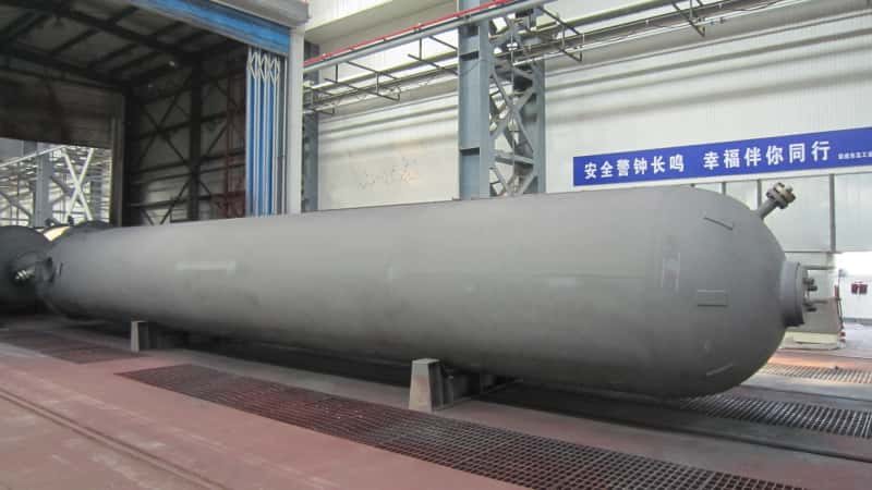

Shipping a large pressure vessel across an ocean sounds straightforward until the rigging crew finds the lifting lug calculations don’t match the actual center of gravity, the saddle spacing wasn’t reviewed for dynamic sea loads, and the corrosion protection applied for a dry inland climate is completely wrong for a tropical port destination. Delays at that point aren’t measured in hours. Customs holds, re-engineering of transport frames, and demurrage charges stack up fast — easily consuming weeks of schedule and tens of thousands of dollars before the vessel even reaches the load port. Getting export preparation right is an engineering discipline, not a checklist item.
Large pressure vessels are prepared for export through a coordinated sequence of post-inspection corrosion treatment, engineered transport support design, load-case-specific lifting and skidding calculations, custom heavy-lift packaging, and documentation packages aligned to the destination port’s customs and inspection requirements. Each step must be completed in the correct order, with sign-off from both the manufacturer and the transport engineer, before port delivery.
What most procurement managers don’t realize is how much the preparation scope changes depending on the vessel’s weight class, the corrosion environment of the destination, and which port in the supply chain introduces the highest risk. A 40-tonne horizontal separator routed through a temperate northern European port is a fundamentally different logistics problem than a 280-tonne column destined for a humid Southeast Asian EPC site — and treating them the same way is where projects quietly bleed money.
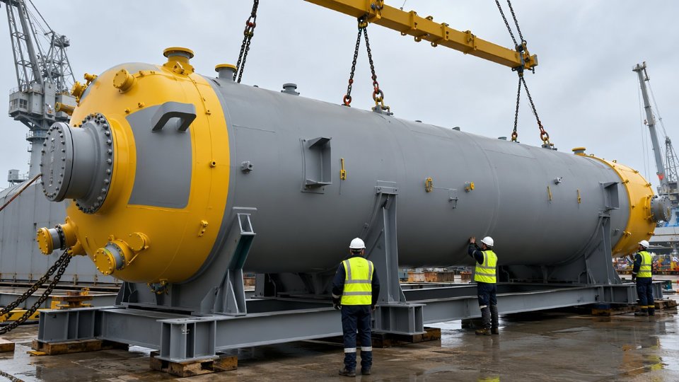
Surface Treatment and Corrosion Protection Specifications Before Crating
A pressure vessel that survives fabrication and inspection can still arrive at its destination port with active corrosion, delaminated coatings, or contaminated internals — all because corrosion protection was treated as a checkbox rather than an engineering task. For any carbon steel vessel destined for ocean freight, the surface preparation grade and coating system are as specification-driven as the weld procedure. Getting them wrong costs real money: strip-and-recoat at a destination yard typically runs two to four times the original surface preparation cost, and that assumes the base metal hasn’t already pitted.
Surface Preparation Grades and When Each Applies
ISO 8501-1 defines the industry reference grades. Sa 2.5 — near-white blast — is the standard floor for marine export on carbon steel vessels. It removes mill scale, rust, and contaminants to the point where only light staining remains in pits. Sa 3, white metal blast, is reserved for situations where the coating system requires maximum adhesion: vessels going to tropical or high-humidity destinations (ISO 9223 corrosion category C4 or C5), voyages exceeding 60–90 days, or where the applied DFT will exceed 350 microns with a zinc-rich primer. The difference in blasting cost between Sa 2.5 and Sa 3 is roughly 15–30%, but the adhesion improvement on a long transit is not marginal — it’s the difference between a coating that stays bonded through thermal cycling and one that blisters at the flange faces.
Surface profile (anchor pattern) matters equally. A 40–75 µm Rz profile is typical for epoxy primer systems; verify this with a replica tape reading, not just a visual pass.
External Coating System Structure and DFT Requirements
The standard three-coat system for carbon steel pressure vessels in marine export:
A zinc-rich epoxy primer (organic or inorganic) applied at 60–80 µm DFT provides sacrificial cathodic protection if the topcoat is breached. An intermediate epoxy coat — typically a high-build epoxy — adds barrier thickness, usually 100–150 µm per coat. A polyurethane or modified epoxy topcoat at 50–80 µm provides UV resistance and mechanical protection during handling and sea passage.
Total system DFT typically falls between 200 and 400 microns, depending on corrosion class, voyage duration, and whether the vessel will be installed outdoors on arrival. A vessel going to a sheltered indoor facility after a 25-day transit needs a different specification than one being installed on a coastal offshore platform. Holiday testing at 1,500–2,000 V DC (wet sponge for thinner systems, high-voltage spark for anything above 250 µm) is mandatory before crating, not optional.
Internal Corrosion Inhibitor Selection
Internal protection is where decisions get more nuanced. Three primary options exist, and they’re not interchangeable.
VCI (vapor corrosion inhibitor) film or foil is appropriate for vessels with limited nozzle access and relatively small internal volumes — generally under 20 m³ — on voyages under 45 days. VCI compounds volatilize and form a molecular protective layer on ferrous surfaces, but their effectiveness drops sharply in large volumes with poor vapor distribution or when internals like trays, baffles, or structured packing are already installed, since packing beds obstruct vapor circulation.
Nitrogen purging and blanket maintenance is the preferred method for vessels with complex internals or those exceeding 45-day voyage windows. The vessel is purged to below 1% O₂ and sealed; a nitrogen blanket at slight positive pressure (typically 0.05–0.1 bar) is maintained and verified before container sealing or crating. This requires pressure-rated blind flanges on all nozzles and a documented nitrogen charge record. Port hold times of 5–14 days at Chinese export hubs like Shanghai, Tianjin, or Qingdao mean the blanket must account for dwell time plus voyage duration — not voyage duration alone.
Desiccant packs are a supplementary measure, not a standalone solution for carbon steel. They’re genuinely effective for stainless vessels where the corrosion risk is chloride-induced pitting rather than general oxidation.
Nitrogen purging alone eliminates all internal corrosion risk during marine transportFalse
Nitrogen blanketing controls oxidation but does not protect against chloride contamination from condensation at flange faces or improperly sealed nozzles. Physical sealing integrity and nozzle cover specification remain critical independent steps.
Special Cases That Demand Separate Attention
Stainless steel vessels face electrolytic contamination risk from chloride exposure during transit — sea spray, salt-laden air, even contact with carbon steel lifting gear can initiate chloride-induced stress corrosion cracking (Cl-SCC) on austenitic grades. External surfaces should be protected with strippable polyethylene film or purpose-formulated stainless-compatible coating, and all contact surfaces during transport must use stainless or nylon slings, not bare carbon steel.
Clad vessels — carbon steel shell with stainless, titanium, or nickel alloy weld overlay — present a coating compatibility problem at weld overlay boundaries. The cladding material and the base metal expand and contract at different rates; a coating system optimized for carbon steel can fail at the transition zone under thermal cycling during a voyage. Separate surface preparation procedures and compatible coating specifications for each zone should be called out explicitly in the coating specification document.
Vessels with internals already installed require a formal internal protection access assessment before sealing. If structured packing or tray decks are in place, VCI vapor cannot reach the vessel shell uniformly. The protection method must be selected with this geometry in mind, and inspection records should confirm that inhibitor distribution is adequate — not assumed.
Documentation Package Required Before Crating
The corrosion protection documentation package that should accompany every vessel to the port, and be available for third-party verification:
| Document | Key Content Required |
|---|---|
| Blast inspection record | Grade achieved, profile measurement (replica tape), ambient conditions at time of blast |
| Coating application log | Coat-by-coat DFT readings, batch numbers, pot life compliance |
| Holiday test report | Test voltage, equipment calibration record, holiday locations and repair status |
| Internal protection method statement | Method selected, N₂ purity/pressure log or VCI batch record, nozzle sealing checklist |
| Third-party inspector sign-off | Inspector credentials, scope of inspection, final acceptance statement |
A third-party inspector signature on the coating records is not a formality. Destination-country customs authorities and EPC project teams increasingly require it as a condition of final acceptance. Missing records at port have caused real demurrage costs — vessels held while documentation is reconstructed from workshop records across multiple time zones.
Nozzle, Flange, and Internal Component Protection: Sealing and Blinding Protocols
Corrosion protection on the shell gets most of the attention during export preparation. The nozzles, flanges, and internals get neglected — and that is where transit damage quietly accumulates. A vessel arriving at site with pitted flange faces, moisture-swollen packing, or corroded stud threads adds weeks of remediation work before commissioning can begin. The cost is rarely the replacement parts themselves; it is the schedule impact and the finger-pointing between fabricator and shipper over who is liable.
Flange Blinding: Matching Protection Class to Pressure Rating
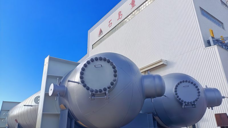
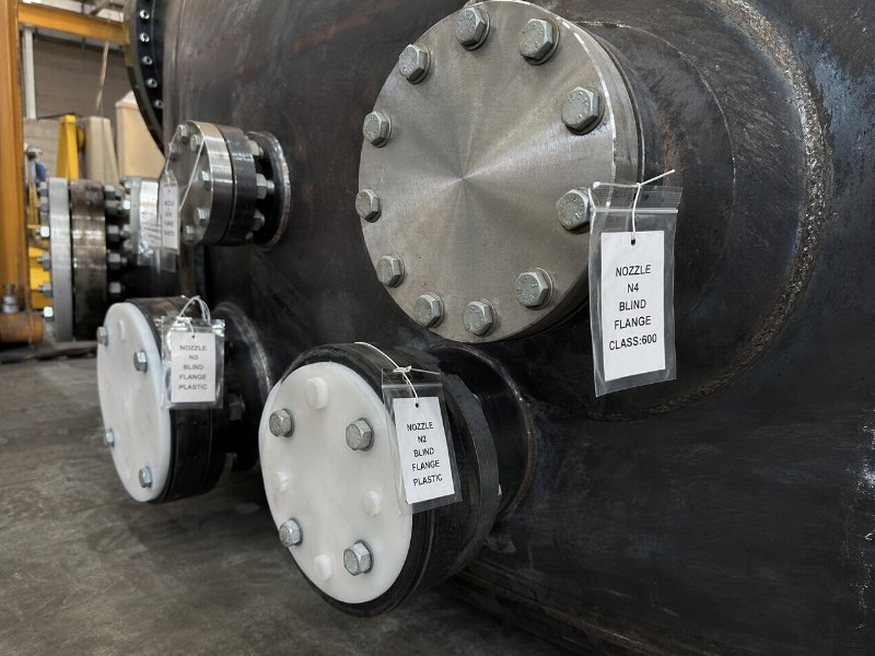
The protection level applied to each flange opening should be proportional to the mechanical and sealing demands that flange will face in service. For Class 600 and above — typically found on high-pressure separator nozzles, reactor inlet and outlet connections, and column reboiler nozzles — steel blind flanges are the correct choice. They are machined to the same face finish as the mating flange, torqued down with the same stud specification the vessel schedule calls for, and they physically prevent any mechanical damage to the seating surface during lifting and transport.
For lower-pressure nozzles, Class 150 and 300 carbon steel flanges included, heavy-duty HDPE blanks are practical and cost-effective. The critical detail most fabrication shops miss: a full-face rubber gasket — minimum 3 mm thickness, Shore A hardness in the 60–70 range — must seat between the HDPE blank and the flange face. Without it, vibration during road transport and vessel roll will micro-abrade the flange face against the plastic blank. That damage is subtle enough to pass a visual inspection but severe enough to cause a gasket leak on first pressurization.
Blind flange torque values must be documented. A torque record matched to each nozzle tag number becomes part of the shipping dossier and gives the receiving inspector a baseline for disassembly.
Bolt and Stud Hardware: Storage and Traceability
Stud sets for large nozzles should not be left threaded into the flange during sea shipment. Hot-dip galvanized or zinc-spray coated hardware — depending on voyage duration and destination humidity class — should be bagged individually in moisture-barrier polyethylene, sealed, desiccated, and tagged with the nozzle identification number from the vessel’s nozzle schedule. A manifest cross-referencing each bag to its nozzle position travels with the shipping documentation. This sounds administratively burdensome. In practice, it takes one afternoon at the fabrication shop and saves a site team from hunting through unlabeled hardware bags in a port warehouse.
Small-Bore Connections and Instrument Nozzles
Threaded instrument nozzles, vent and drain connections, and small-bore process taps — anything under DN50 — get threaded carbon steel or stainless plugs with two wraps of PTFE tape, followed by a secondary wrap of self-amalgamating tape over the entire cap assembly. The secondary tape layer is the moisture seal; the plug itself is the mechanical protection. Any connection left with only a plastic push-in cap is a liability. Push-fit caps vibrate loose. PTFE-taped threaded plugs do not.
Protecting Installed Internals Before Closure
Demister pads, structured packing sections, and tray assemblies present a specific challenge: they are fragile, positionally sensitive, and often proprietary. Each installed internal element should be wrapped individually in VCI (vapor corrosion inhibitor) film before the vessel is closed for shipment. VCI film releases a corrosion-inhibiting vapor phase that protects metal surfaces within a sealed volume — effective for voyages up to roughly 12 months, depending on film grade and enclosure integrity.
Every wrapped element needs a positional tag — tray number, bed level, orientation reference — because an installer on site cannot always determine correct positioning from the vessel drawing alone if components have shifted.
VCI film provides adequate corrosion protection for installed metallic internals during sea shipment without requiring desiccants inside sealed packing assembliesFalse
VCI film and desiccants serve different mechanisms. VCI film inhibits surface corrosion through vapor-phase chemistry. Desiccants control bulk humidity inside the vessel cavity. For voyages exceeding 4–6 weeks, particularly through tropical or high-humidity routing, both are needed. Using only VCI film without desiccant management inside the vessel shell is insufficient for sensitive internals.
Pre-Shipment Internal Inspection and Closure Documentation
The final internal inspection is a witnessed, documented event — not a walkthrough. The checklist covers cleanliness verification (no weld spatter, debris, or moisture pooling on the vessel floor), desiccant quantity and placement recorded against a moisture-load calculation based on internal volume and voyage duration, and moisture indicator card positioning at locations representative of the vessel’s internal atmosphere.
Once closed, manway and closure blind torque values are recorded, and photographic evidence of each sealed opening is taken and filed. These closure photographs carry real weight if a dispute arises over whether moisture ingress occurred before or after the vessel left the fabrication yard.
Structural Transport Engineering: Saddles, Cradles, and Skid Design for Heavy-Lift Loads
The assumption that fabrication saddles can double as sea-transport supports is one of the most consistent sources of structural failure in large vessel shipments. It seems logical — the saddle held the vessel in the shop, so why not on deck? The problem is that the load case is entirely different. A fabrication saddle is designed for static vertical load under controlled yard conditions. A vessel on a cargo ship experiences dynamic accelerations in three axes simultaneously, with lashing forces introducing horizontal and rotational loads that the fabrication saddle geometry was never intended to resist. On a typical ocean voyage, DNV-ST-N001 marine transport guidelines specify design accelerations in the range of 0.3–0.5g longitudinal and 0.5–0.8g transverse, with the exact values depending on the voyage route, season, significant wave height assumptions, and cargo position on the vessel (deck cargo at bow takes higher accelerations than cargo amidships or below deck). Applying those factors to a 120-tonne vessel makes the difference between a properly engineered cradle and a repurposed fabrication saddle immediately clear in the numbers.
Transport Saddle and Cradle Design: What the Calculations Actually Cover
The starting point is an accurate weight and center-of-gravity (CoG) determination — not the nominal design weight, but the as-fabricated weight including any internal components, residual hydrostatic test water, blind flanges, and temporary closures left in place for shipping. CoG position matters because it directly affects the load split between forward and aft saddles and governs the tipping moment under longitudinal acceleration.
Contact angle for cylindrical shells is standardized at 120° in most transport engineering practice. Going narrower concentrates bearing stress on the shell and risks local buckling at the saddle horn, particularly on thin-walled vessels or those with low shell thickness-to-diameter ratios. Interface pressure verification — comparing the calculated bearing pressure at the saddle contact zone against the allowable stress for the shell material and thickness — is a non-negotiable calculation step, not a checkbox. Base plate sizing follows from the deck or trailer bed bearing capacity and the required load spread.
Horizontal Transport of Vertical Vessels: Skid and Intermediate Support Design
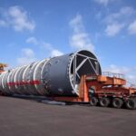
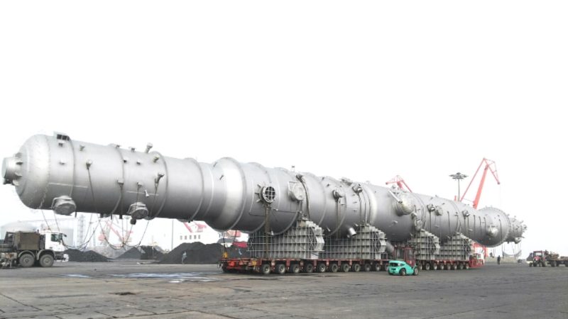
Tall vertical vessels — columns, reactors, and regenerators with L/D ratios above roughly 8:1 — require particular attention when laid horizontal for transport. The bending moment at mid-span under dynamic loads can be significant, and two-point support is often insufficient. Common practice places intermediate support rings at locations determined by bending moment distribution, with the number of supports scaling with vessel length and weight. A vessel 30 meters long and over 80 tonnes will typically need a minimum of three support points; longer or heavier vessels may need four or five.
Anti-rotation brackets welded to the skid frame prevent the vessel from rolling under transverse acceleration. These are simple in concept but must be sized for the actual transverse load, not guessed. Pad eyes and bracket welds on transport skids need full-penetration weld procedures with documented WPS and inspection records — not fillet welds laid by a fitter without oversight.
Sea-Fastening Design and the Marine Warranty Surveyor’s Role
Lashing arrangement design specifies the number, diameter, breaking load, and angle of wire rope or chain lashings, along with turnbuckle working load ratings and the pad eye capacities on both the vessel saddle and the ship’s deck. Lashing angles below 30° from horizontal reduce vertical restraint efficiency substantially and should be avoided where deck geometry allows.
A marine warranty surveyor's approval of the sea-fastening arrangement is typically required by cargo insurers before an oversized vessel shipment is covered.True
Major cargo insurers and P&I clubs routinely require a Marine Warranty Survey (MWS) certificate for heavy-lift and oversized deck cargo. DNV, Lloyd's, and Bureau Veritas all offer this service. Without it, insurance coverage for the cargo during transit may be void or disputed after a loss event.
The marine warranty surveyor reviews the transport engineering calculations, inspects the physical sea-fastening on board before departure, and issues a certificate of approval. Suppliers who treat this as bureaucratic overhead rather than a genuine risk control step tend to find out why it exists the hard way.
The Transport Engineering Report as a Procurement Deliverable
Buyers should require the transport engineering report as a named project deliverable, not something produced informally after the vessel leaves the yard. A complete report includes: dynamic load calculations with the acceleration values and their derivation basis; material certificates for all transport structure steelwork; weld inspection records (visual plus relevant NDE) for sea-fastening attachment welds; and the classification society approval signature. DNV, Lloyd’s Register, and Bureau Veritas are the recognized bodies for this work. Safety factors on transport structure loads typically run 1.5–2.0x the calculated static equivalent, with the specific factor depending on the classification society standard applied and the voyage risk category. Any supplier who cannot produce this documentation is transferring structural risk to the buyer.
Rigging Plans, Lift Lug Certification, and Load-Out Procedures at the Fabrication Yard
Lifting a large pressure vessel off its fabrication stand is one of the highest-consequence single activities in the entire export preparation sequence. A rigging failure at this stage does not just damage equipment — it can write off months of fabrication work, injure personnel, and trigger marine insurance disputes that delay project schedules by quarters. Yet many procurement managers and EPC project engineers never ask to see the lift engineering package until after an incident prompts the question.
Lift Lug Design and Certification Requirements
Lift lugs are pressure-retaining-adjacent weldments and must be treated with the same documentary rigor as a nozzle attachment. Material certificates with full heat and charge number traceability are non-negotiable — a lug fabricated from untraced plate introduces liability that no marine insurer will accept quietly. The weld procedure specification (WPS) and its supporting procedure qualification record (PQR) must cover the actual base material combination, thickness range, and preheat regime. For carbon steel shells above roughly 30 mm wall thickness, preheat requirements on lug attachment welds frequently fall between 100–150 °C; getting this wrong produces hydrogen-assisted cracking that may not surface until load is applied.
NDE requirements follow attachment weld classification. Magnetic particle testing (MT) or liquid penetrant testing (PT) on the accessible weld surface is standard. For shells above approximately 38 mm thickness, ultrasonic testing (UT) of the attachment zone is warranted to detect subsurface laminar defects in the shell plate itself — a vessel that passed radiography on its longitudinal seam can still carry rolling laminations that concentrate stress directly beneath a lug. Proof load documentation, typically at 100–125% of the design lift load per DNV-ST-N001 or equivalent, closes the certification loop.

Center-of-Gravity Calculation and Rigging Geometry
The center-of-gravity (CoG) calculation is not a formality — it directly dictates sling attachment points, sling lengths, and the selection of any spreader beam. For vessels with asymmetric internal components (demister pads, distributor trays, packed sections), the CoG shifts significantly from the geometric centerline. A CoG error of 200–400 mm can produce an uncontrolled tilt during the lift that overloads one sling leg well beyond the rated capacity.
Sling angles must not fall below 60° from horizontal. Below this threshold, the compressive horizontal component acting on the vessel shell increases sharply, and on thin-wall vessels or vessels with large-diameter nozzles near the lift zone, shell distortion becomes a real risk. Dynamic amplification factor (DAF) selection — typically 1.1 to 1.3 depending on crane type and lift height per DNV guidelines — must be explicitly applied in the rigging study, not absorbed implicitly into “engineering judgment.”
A sling angle below 45° from horizontal doubles the compressive load on the vessel shell compared to a vertical lift, relative to the same gross lifted weight.True
Basic vector mechanics: the horizontal component of sling tension equals the vertical component multiplied by the cotangent of the sling angle. At 45°, horizontal and vertical components are equal; below 45° the horizontal component exceeds the vertical load, significantly increasing risk of shell deformation or lug weld overstress.
Pre-Lift Checklist: Crane, Ground, Weather, and Exclusion Zones
Crane capacity verification goes beyond nameplate tonnage. The specific configuration — boom length, operating radius, outrigger spread — determines the actual de-rated capacity at the lift point. A crane rated at 500 tonnes may deliver only 280–320 tonnes at the radius required to clear the fabrication bay structure. Ground bearing pressure at outrigger pad locations must be assessed against a geotechnical survey or at minimum a conservative assumed bearing capacity; soft yard fill under crane mats has caused catastrophic crane collapses during heavy industrial lifts.
Wind speed criteria for bare lifts on large-diameter vessels are typically set at 10 m/s maximum, though sail-area calculations on tall columns may push that threshold lower — sometimes to 7–8 m/s — when projected wind load on the vessel creates significant lateral moment at the hook. Personnel exclusion zones must be physically established, not just declared verbally: barriers or spotters positioned at a minimum radius equal to the vessel length plus 10 m is a defensible minimum.
Load-Out to SPMT or Barge
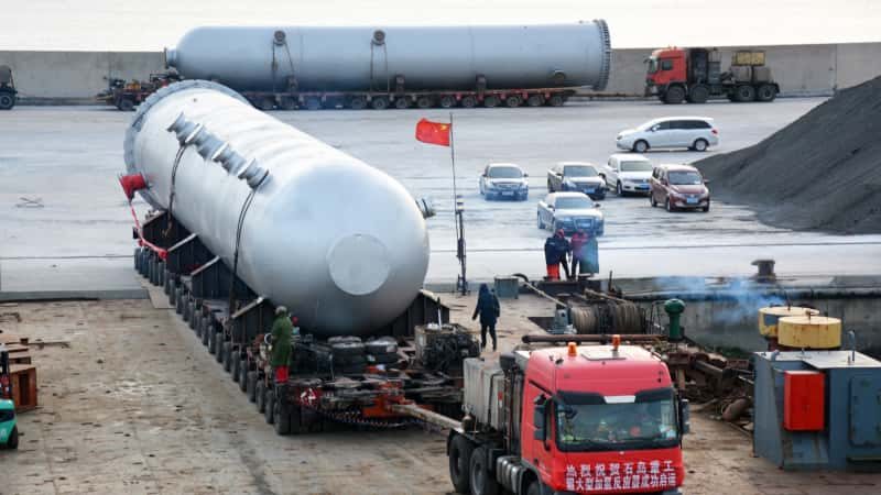
Once the vessel is lifted and positioned over the transport vehicle, the load transfer sequence matters as much as the lift itself. Self-propelled modular transporter (SPMT) axle line load distribution must be verified against the transport engineering calculation before the crane releases load. The transition from dynamic crane hook load to static SPMT support is where cribbing and blocking sequences become critical — a partially transferred load on misaligned blocking has caused saddle flange failures on vessels that survived the lift without incident.
Survey verification — typically by the marine warranty surveyor (MWS) or an independent third-party inspector — confirms that the vessel is correctly seated on transport saddles, that blocking is tight, and that no shell distortion has occurred before the crane hook is disconnected. This sign-off is not bureaucratic overhead; most cargo marine insurance policies require it explicitly.
Documentation Package
The complete lift documentation package should include the lift study report (calculations, rigging arrangement drawings, equipment data sheets), a rigging register listing every piece of rigging hardware with its certificate and SWL, the third-party lift supervisor sign-off sheet, and photographic or video evidence of the actual lift execution. EPC clients with offshore or refinery end destinations increasingly specify video evidence as a contractual deliverable — it protects both the fabricator and the buyer in the event of a transit damage claim where the origin condition of the vessel is disputed. Keeping this package with the vessel documentation file, not archived separately at the fabrication yard, prevents the weeks-long retrieval delays that routinely surface during marine insurance surveys.
Outer Packaging, Weather Protection, and Marking Requirements for Sea Freight
For very large pressure vessels — horizontal drums over 6 meters in length, tall vertical columns, or any item exceeding roughly 20–30 tonnes — full timber or steel crating is simply impractical. The vessel itself becomes its own structural unit. In these cases, the packaging strategy is bare vessel with coating and blinding already applied, secured to its transport saddles, with weather protection built up in layers directly over the shell. That distinction matters for procurement teams writing packaging specifications: the crating tier you specify should match the vessel size and alloy class, not default to one standard approach across all line items.
Packaging Tiers Matched to Vessel Type
The three practical tiers work like this. First, bare vessel with full corrosion protection and blinded nozzles — used for large columns, separators, and heavy-wall reactors where the weight and dimensions make enclosure unworkable. Second, partial open-top timber framing built around nozzle clusters, manways, and instrument connection zones that protrude beyond the shell envelope. These frames protect the most vulnerable geometry during handling without adding the cost or weight of full enclosure. Third, fully enclosed timber or steel crating for smaller vessels, high-alloy equipment (duplex stainless, titanium-clad), or items where the entire exterior surface carries a high replacement cost if damaged in transit. For the third tier, steel crating is worth the additional fabrication cost — typically 30–60% more than equivalent timber — when the destination port has aggressive handling conditions or the voyage involves transshipment.
Weather Protection Sheeting: Sequence and Mechanics
Applied correctly, weather protection is a system, not a single wrap. The sequence that holds up on a 30–45 day voyage to a humid equatorial port: first, a VCI (volatile corrosion inhibitor) film layer directly against any bare metal or primed surface, emitter side facing in; second, a UV-stabilized polyethylene outer sheet, minimum 200 microns, secured with strapping at 600–900 mm intervals. Between the two layers, leave a deliberate ventilation gap — typically 20–40 mm — maintained by foam spacers or timber battens at the lower edges. Skip this gap and you trap condensation against the VCI film, which defeats its purpose entirely.
Sharp flange faces, stud bolt ends, and protruding thermowell bosses will puncture the outer sheeting under ship motion unless mechanically protected first. Foam pipe lagging split lengthwise and taped over flange ODs, or purpose-cut neoprene sheet pads held with strapping, adds less than an hour of labor per vessel and prevents the kind of transit damage that shows up as corrosion staining around nozzle zones at destination — damage that is almost always disputed between shipper and receiver.
ISPM 15 Timber Compliance — Non-Negotiable for Most Destinations
Any timber used in packing — dunnage, crating frames, blocking, bracing — must carry ISPM 15 certification, either heat-treatment (HT) to 56°C core temperature for 30 minutes or approved methyl bromide fumigation, with the official IPPC mark stamped on each piece. This is mandatory for import into the US, all EU member states, Australia, and virtually all Middle East project destinations. Failing this at discharge port means the timber is seized, fumigated at the consignee’s cost, or the shipment is held pending inspection — port dwell time extending by days, sometimes triggering demurrage charges against the seller under EXW or FOB terms.
ISPM 15 non-compliant timber packaging will be rejected or fumigated at the importer's cost at US, EU, and Australian portsTrue
ISPM 15 (International Standards for Phytosanitary Measures No. 15) is enforced by customs and biosecurity authorities in these jurisdictions; non-compliant timber triggers mandatory remedial action or shipment hold
Shipping Marks, Labels, and IMDG Considerations
Marking requirements are not aesthetic — they are operationally functional and in some cases legally required. Every package, transport frame, and crated item should carry: gross weight and net weight (in kg, not rounded to the nearest tonne), center of gravity cross-marking on all four faces of the package, lift point indicators aligned with the actual rigging attachment positions on the saddle or skid, and ISO 780 handling symbols for FRAGILE, NO STEP, and THIS SIDE UP where applicable.
For vessels that held hazardous process media during factory testing — amine systems, hydrocarbon service, certain acid-cleaned alloy vessels — confirm with the shipper’s IMDG (International Maritime Dangerous Goods) coordinator whether any residual classification applies. Even trace hydrocarbon residue from a hydrostatic test using process fluid rather than clean water can trigger a placard requirement. Getting this wrong at load-out creates a port security incident, not just a paperwork delay.
Documentation Traveling with the Package
The physical paperwork package should include: a detailed packing list itemizing every component, blind flange, loose bolt set, and instrument shipped with the vessel; a weight and dimension certificate issued by a certified weighing station (not the fabricator’s own scale); a photographic inspection record taken immediately before wrapping, with timestamps, covering all nozzle blind installations, coating condition, and identification plate legibility; and for multi-item shipments sharing a single transport frame or skid, a contents manifest that maps each item number to its physical position on the frame. That last document saves hours of confusion at destination when the receiving inspector and the crane operator are trying to identify which vessel comes off the trailer first.
Export Documentation, Customs Compliance, and Third-Party Inspection Coordination
Getting the engineering right on a large pressure vessel means nothing if the paperwork package is incomplete, mismatched, or arrives at the destination port three days after the equipment does. For overseas EPC buyers, documentation failures are among the most common — and most expensive — causes of customs holds, demurrage charges, and project schedule slippage. Understanding what is required, who issues it, and when it must be ready is as operationally critical as the coating spec or the lift plan.
The Core Export Documentation Set
Every large pressure vessel shipment should travel with a tightly cross-referenced document package. The commercial invoice must state the precise equipment description, HS code, unit value, and Incoterms clearly — any ambiguity between the invoice and the bill of lading gives customs authorities grounds to query or detain the shipment. The packing list needs to itemize not just the main vessel but every loose-shipped item: blind flanges, anchor bolts, nameplate copies, touch-up paint kits, and any companion documentation packaged inside the crate.
Material test certificates (MTCs) for all pressure-retaining components — shell plates, heads, nozzle forgings, weld filler materials — must be originals or certified true copies. Destination country inspectors, particularly in the Middle East, Southeast Asia, and parts of South America, frequently request these at port. If they are missing, expect delays of one to three weeks while the manufacturer retrieves and apostilles replacements.
The certificate of origin matters commercially, not just procedurally. A Form A (Generalized System of Preferences) or a standard CO issued by the relevant Chamber of Commerce can determine whether the buyer qualifies for preferential import duty rates. On equipment valued in the low seven figures, a two to five percentage point tariff difference is real money. Confirm with your trade compliance team which form is accepted under the bilateral trade arrangement between the exporting country and your destination before fabrication completes — not the week before shipment.
Statutory Certification and What Travels With the Equipment
The certification regime the vessel was built under dictates what documentation must physically accompany the equipment versus what the manufacturer retains. An ASME U-stamp vessel requires the Manufacturer’s Data Report (Form U-1 or U-1A), which must be available to the end user and the authorized inspection agency. For PED CE-marked vessels destined for EU or EU-aligned markets, the Declaration of Conformity and the Technical File reference must be provided; the full technical file stays with the manufacturer but must be producible on request for ten years. Chinese TS-licensed vessels carry a special equipment manufacturing license number on the nameplate and require a corresponding certificate of conformity issued by the notified body.
A vessel's ASME U-stamp does not automatically satisfy PED CE marking requirements, and the two certifications require separate design reviews, different documentation structures, and different third-party involvement.True
ASME and PED are parallel but distinct regulatory frameworks. ASME governs design and fabrication per US standards; PED is an EU market access directive requiring conformity assessment by an EU-recognized notified body. Dual certification is achievable but requires deliberate planning during the design phase, not at shipment.
Misrepresenting or omitting certification status on shipping documents is not a minor clerical error. It can result in the equipment being classified as uncertified goods at destination, triggering re-inspection, duties on the full replacement value, or outright rejection.
Third-Party Inspection Coordination
Most EPC contracts and many letters of credit require a pre-shipment inspection (PSI) by an independent agency — Bureau Veritas, SGS, Intertek, and similar firms are commonly specified. Scheduling this correctly is where suppliers and buyers frequently fail each other.
The PSI scope must be defined in writing before the inspection agency is engaged. A scope that says only “inspect per contract” gives the inspector no usable basis for their certificate. Specify exactly what is being verified: dimensional checks against approved drawings, surface coating DFT readings, nameplate data confirmation, hydrostatic test witness or document review, and packing completeness. The output — an Inspection Release Note (IRN) or Pre-Shipment Inspection Certificate — is what many destination customs authorities will actually look at. Without it, clearance can stall regardless of how complete the rest of the documentation is.
Inspector access at the fabrication yard requires advance coordination of typically five to ten working days for a named agency to mobilize. Build this into the shipping schedule, not as a parallel task but as a gate. Equipment that is loaded before the IRN is issued creates a situation where the vessel is at sea but the document is still being processed — a situation that routinely leads to port dwell time running past the fourteen-day range typical at major Chinese export hubs, compounding berth fees and demurrage.

HS Code Classification and Export Control Screening
Pressure vessels most commonly fall under HS Chapter 84.19 (industrial or laboratory equipment for treating materials by temperature change) or 73.09 (reservoirs, tanks, and similar containers of iron or steel, capacity exceeding 300 liters). The correct classification depends on function, not just form. A reactor with internal heat exchange elements classified under 73.09 instead of 84.19 — or vice versa — can trigger additional duties, delays, or a formal customs query that takes weeks to resolve at destination.
Get a binding tariff ruling from your customs broker before the commercial invoice is issued. This is a two to five day exercise that eliminates a risk category entirely.
Dual-use and sanctions screening deserves direct attention. Certain pressure vessel configurations — particularly those designed for high-pressure gas service, specific chemical processes, or nuclear-adjacent applications — may fall under export control classifications requiring an export license assessment under EAR (US Entity List and Commerce Control List), EU Dual-Use Regulation, or equivalent national frameworks. The manufacturer has an obligation to screen the end-use declaration provided by the buyer. The buyer has an obligation to disclose the accurate end-use, end-user, and final destination — not the EPC hub country, but the actual operating site and process application. Providing inaccurate end-use information to bypass export controls is a legal liability that rests with both parties. Build this screening step into the purchase order terms, not as boilerplate but as a documented exchange with sign-off on both sides.
Port Delivery Boundary Conditions: Defining CIF, DAP, and EXW Handover Points Operationally
Incoterms disputes are among the most expensive and time-consuming commercial conflicts in heavy equipment project cargo. When a 180-tonne pressure vessel sits at a Chinese load port with unclear responsibility for crane hire, sea-fastening, or marine survey sign-off, the daily cost of delay — berth demurrage, vessel standby, port storage — accumulates fast. Getting the operational boundary of each term defined contractually, before fabrication starts, is not administrative overhead. It is risk management.
EXW (Ex-Works): The Buyer Carries Nearly Everything
Under EXW, the seller’s obligation ends at their factory gate. In practice for large pressure vessels, this means the buyer must arrange loading supervision at the fabrication yard, export customs declaration, SPMT or heavy transport from yard to port, and all lashing and sea-fastening work. The seller is still obligated to provide the packing list, commercial invoice, certificate of origin, material test reports, and any third-party inspection release certificates — but takes no further responsibility once the vessel is released from the yard.
The common failure point here: buyers from outside China frequently underestimate what export customs clearance requires for pressure vessels classified as special cargo. HS code classification, export license validity for certain alloy materials, and customs commodity inspection (CIQ) release can add 5–10 working days if not prepared in advance. An EXW buyer who has not pre-engaged a licensed Chinese freight forwarder with project cargo experience will absorb that delay entirely.
FOB (Free on Board): Where Engineering and Commerce Intersect at the Berth
FOB is the most contested term in pressure vessel project cargo contracts. The seller’s responsibility ends when the vessel is loaded and secured on board the ocean-going ship. Getting to that point involves SPMT transport from fabrication yard to berth, stevedoring, specialized port crane hire (often 500–1,200-tonne capacity for large vessels), and — critically — sea-fastening welding on deck and marine warranty surveyor (MWS) acceptance before hook release.
Who pays for the MWS is consistently disputed. Under a strict FOB reading, the seller arranges and pays for everything up to the ship’s rail. But many sellers quote FOB assuming the buyer’s nominated vessel operator carries the MWS cost. Specify this explicitly in the sales contract. The MWS cannot be bypassed — most marine underwriters will void the cargo policy if the surveyor has not signed off on sea-fastening adequacy before departure.
Under FOB terms, the seller bears responsibility for sea-fastening welding costs on the vessel deck.False
Sea-fastening on deck is typically the responsibility of the vessel operator or charterer, not the cargo seller, even under FOB — unless the contract explicitly assigns this cost to the seller. This is one of the most commonly misunderstood cost boundaries in project cargo contracts.
CIF (Cost, Insurance, Freight): Risk Transfers Earlier Than Most Buyers Realize
CIF is widely misread as meaning the seller remains responsible until the cargo arrives safely. It does not. Risk transfers to the buyer at the load port — the same point as FOB. The seller arranges and pays freight and marine insurance, but if the vessel is damaged in transit, the buyer files the claim against the seller’s policy. For pressure vessels, the insurance scope should be ICC-A (all-risk), not ICC-C. Confirm this in writing. Heavy-lift conditions, special stowage requirements, and any on-deck carriage must be declared to the underwriter; undeclared conditions give insurers grounds to reduce or deny settlement.
Freight under CIF must be contracted with a carrier experienced in project cargo — semi-submersible vessels, heavy-lift vessel operators, or breakbulk operators with deck capacity. General container freight rates are irrelevant here. Freight for a single large vessel shipment from a major Chinese export hub to a Middle Eastern or Southeast Asian destination typically ranges from $80,000 to $350,000+ depending on vessel dimensions, weight, port pair, and market conditions at time of booking.
DAP (Delivered at Place): Boundary Creep Is a Real Commercial Risk
DAP extends the seller’s responsibility to a named destination — but the named place matters enormously. Most manufacturers offering DAP price to the destination port gate, not the project site. Inland transport from port to site in many project destinations (remote refinery locations, greenfield chemical parks) requires special transport permits, escort vehicles, and route surveys that can take weeks to arrange and cost as much as the ocean freight. Buyers who assume DAP includes site delivery without confirming the named place in writing routinely find themselves absorbing costs they budgeted to the seller.
Under DAP, the buyer remains responsible for import customs clearance and must hold a valid import license for the equipment category. For pressure vessels entering markets with strict equipment import regulations — India, Saudi Arabia, Indonesia among others — the import licensing timeline should be started no later than when fabrication begins.
Incoterms Boundary Comparison for Heavy Pressure Vessel Shipments
| Incoterms Term | Seller Responsible For | Buyer Responsible For | Risk Transfer Point | Most Common Dispute |
|---|---|---|---|---|
| EXW | Documentation at factory gate | Loading, export customs, all transport and insurance | At factory gate | Export customs delay; CIQ release not prepared |
| FOB | SPMT to berth, stevedoring, port crane, sea-fastening, MWS sign-off | Ocean freight, marine insurance, import | At ship’s rail, load port | Who pays MWS; sea-fastening cost allocation |
| CIF | Freight contract, ICC-A marine insurance, sea-fastening coordination | Import customs, unloading at destination | At ship’s rail, load port | Insurance scope (ICC-A vs. C); undeclared heavy-lift conditions |
| DAP (port gate) | All freight and insurance to destination port gate | Import license, unloading, inland haulage to site | At named place (port gate) | Buyer assumes site delivery is included; inland permit delays |
| DAP (project site) | All of above plus inland transport and permits to site | Import customs clearance only | At project site | Route survey not completed; site readiness not confirmed |
The pattern across all these terms is consistent: disputes arise not from the Incoterms rules themselves, but from the gap between what the standard term says and what each party assumed it covered. For heavy non-standard pressure vessels, every boundary — who calls the crane, who signs the MWS release, which party holds the import license — should be listed as a numbered contractual obligation, not inferred from the Incoterms abbreviation alone.
Frequently Asked Questions About Pressure Vessel Export Shipping and Port Delivery
What is the maximum pressure vessel size that can ship by standard container, and when is breakbulk or heavy-lift required?
The practical container limit is roughly 12 m in length, 2.35 m outside diameter, and 20 tonnes gross weight — and even hitting two of those three thresholds simultaneously usually pushes the cargo out of ISO container territory. Small, skid-mounted separators and heat exchangers occasionally fit a 20 ft or 40 ft flat-rack, but the moment shell diameter exceeds 2.35 m or the unit needs cradle support extending beyond the flat-rack footprint, you are in breakbulk or project cargo territory. Heavy-lift vessel charters become necessary when a single lift piece exceeds roughly 100–150 tonnes, depending on port crane capacity at origin and destination. Booking lead times for heavy-lift vessels from major Chinese export hubs run 4–10 weeks ahead of required loading date — treat that as a hard project schedule input, not a detail to confirm later.
How long does export preparation typically take after fabrication is complete?
Plan for 3–8 weeks depending on vessel weight class, surface treatment specification, and how early transport engineering was initiated. The compressible tasks — saddle fabrication, documentation compilation — can overlap, but surface treatment cannot be rushed: a high-build epoxy system needs 5–10 days minimum cure time before hard transport loading, and skipping that step causes coating delamination under saddle contact stress. Transport engineering approval from the marine warranty surveyor adds another 5–15 working days if drawings were not submitted early. Compressed timelines cost money in expedite fees and increase the probability of a survey rejection. A realistic milestone plan starts transport engineering no later than two weeks before the final weld inspection.
Who is responsible for the marine warranty survey, and what happens if the vessel fails?
The marine warranty surveyor (MWS) is appointed by the cargo insurer, not the manufacturer or the buyer. Their approval is the insurer’s condition for covering the shipment. A failed survey does not delay the vessel one day — it suspends insurance coverage entirely, meaning the cargo either sits at the yard or ships uninsured, neither of which is acceptable on a capital asset worth millions. The most common failure causes are inadequate sea-fastening weld size, missing or unsigned lift calculations, and a center of gravity position on the shipping documents that does not match the actual weigh-off result. Treat the MWS submittal package — rigging study, CoG calculation, sea-fastening drawings — as a deliverable with its own schedule milestone.
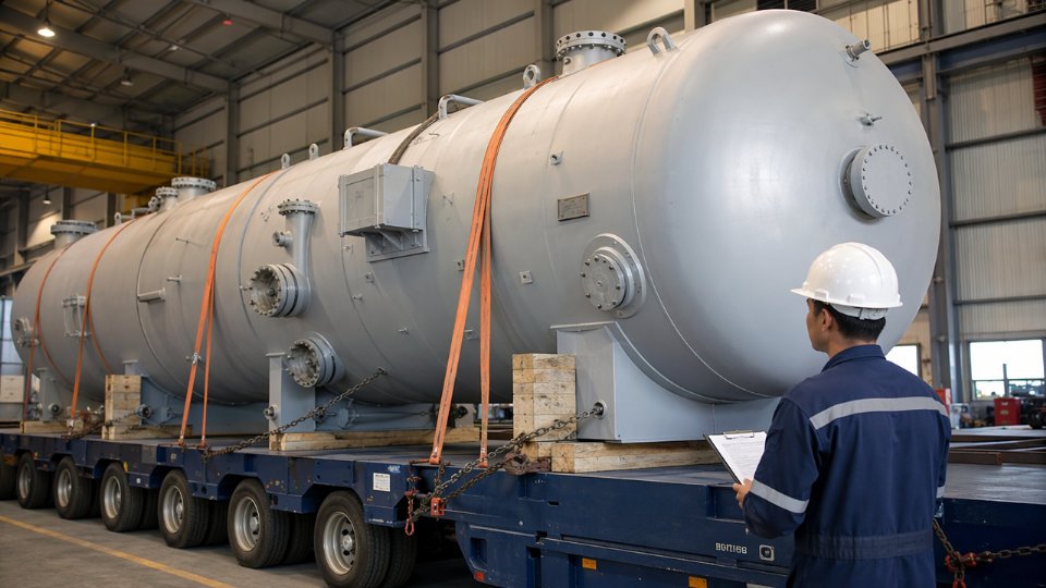
A failed marine warranty survey will void cargo insurance coverage for the shipmentTrue
Marine warranty surveyors are engaged by the cargo insurer as a condition of policy coverage; if the surveyor does not issue approval, the insurer's obligation to cover the shipment does not attach — this is standard practice across Lloyd's and major P&I-affiliated cargo policies
Can nozzle internals and structured packing be installed before shipping, or shipped separately?
Pre-installation is preferable for project schedule but carries real risk if not managed properly. Structured packing and demister pads installed in the shop must be positionally documented with photographs, tagged against the isometric, and protected with VCI film and sealed nozzle blinds. Catalyst beds and random dump packing are almost always loaded on-site — the handling and vibration during sea transport can compact or redistribute fill material enough to alter pressure drop and flow distribution. Agree this scope explicitly with the EPC client in writing before fabrication closes out; late decisions to pre-install or remove packing after surface treatment is complete damage coatings and add cost.
What corrosion protection is required for a 90-day sea voyage to a tropical destination?
The industry baseline is Sa 2.5 abrasive blast plus a 250–350 micron dry film thickness (DFT) epoxy system externally, with an aliphatic polyurethane topcoat for UV resistance if the vessel will be stowed on open deck. Internally, a nitrogen purge held at slight positive pressure with a pressure indicator visible from outside the crate is the cleanest solution; where nitrogen maintenance is not practical, VCI film lining combined with silica gel or molecular sieve desiccant at calculated volume for the voyage duration is acceptable. Desiccant quantity is not a guess — it is sized to the internal void volume and expected humidity exposure, typically using MIL-D-3464 or equivalent as a calculation basis. Longer voyages or ports with extended dwell times in high-humidity conditions require uprated desiccant volume, not just a standard bag count.
How is vessel weight and center of gravity verified for shipping documentation?
Calibrated load cells during the fabrication yard lift, or certified platform scales during load-out, produce a weight certificate that the MWS will require. Center of gravity is calculated from the fabrication drawings — accounting for asymmetric nozzle loads, internal components, and any pre-installed internals — and then cross-checked against the weigh-off result. A deviation greater than roughly 5% between the calculated and measured CoG triggers a revised rigging study before the lift proceeds. This matters operationally: an undocumented CoG shift changes sling angles and hook load distribution, and on a 200-tonne vessel that translates directly into structural overload risk on the lift lugs or the transport saddles.