Liquid carbon dioxide storage and transport projects depend on pressure vessels to keep CO2 within a controlled pressure-temperature envelope from capture and liquefaction through loading, transport, unloading, buffer storage, and injection or utilization. These vessels are not ordinary storage tanks. They are engineered containment systems that must manage phase behavior, heat ingress, pressure rise, low-temperature materials, filling limits, relief protection, instrumentation, and transfer operations.
For EPC contractors, carbon capture developers, terminal operators, and equipment buyers, selecting LCO2 pressure vessels requires more than specifying capacity. The vessel must match the CO2 composition, operating pressure and temperature, transport mode, loading rate, insulation strategy, applicable code, inspection authority, and full logistics chain.
What Is LCO2?
LCO2 means liquefied carbon dioxide. Carbon dioxide can exist as a gas, liquid, solid, or dense-phase fluid depending on pressure and temperature. Its phase behavior is central to vessel and transfer-system design.
The NIST Chemistry WebBook lists the CO2 triple point near 216.6 K and 5.18 bar and the critical point near 304.1 K and 73.8 bar. Liquid CO2 can only exist within the appropriate region between these boundaries. If pressure falls too far during unloading, venting, or depressurization, the liquid may flash and cool rapidly, creating dry ice and potential blockage.
The operating envelope selected for a project influences vessel pressure rating, material toughness, insulation, refrigeration, pump design, cargo density, transfer rate, and emergency procedures.
How Are Pressure Vessels Used in LCO2 Projects?
Pressure vessels can serve several functions across a CO2 logistics chain:
- Capture-site buffer storage between liquefaction and transport
- Truck, rail, portable tank, or ISO tank transport
- Terminal storage before ship loading or pipeline injection
- Marine cargo containment in approved liquefied-gas tank systems
- Receiving-terminal surge storage after unloading
- Intermediate storage for industrial CO2 utilization
- Process vessels for flash separation, vapor return, or pressure control
The required storage duration and flow balance are important. A correctly sized buffer vessel can allow a capture plant to continue operating when transport is delayed, smooth ship or truck loading cycles, and reduce unnecessary venting or shutdowns.
Why Does LCO2 Require Pressure-Rated Storage?
LCO2 cannot be handled like water or atmospheric fuel oil. Its liquid state depends on pressure and temperature. Heat entering the tank causes vapor generation and pressure rise. Pressure loss during withdrawal or venting can cause flashing and rapid cooling.
The vessel therefore provides several safety and process functions:
- Contains CO2 at the approved operating and design pressure
- Maintains material integrity at the minimum design metal temperature
- Limits heat leak through insulation
- Provides vapor space for thermal expansion and pressure control
- Supports controlled liquid withdrawal and vapor return
- Provides connections for relief valves, rupture discs, instruments, and shutdown systems
- Controls filling ratio to prevent hydraulic overfill
Buyers can review broader custom pressure vessels and liquefied gas storage tanks when planning project-specific LCO2 equipment.
Main LCO2 Vessel Applications
Stationary Buffer Storage
Stationary vessels can store liquefied CO2 between capture, liquefaction, transport, and injection operations. Horizontal vessels may be used in industrial facilities and logistics terminals, while project-specific layouts may use multiple vessels to provide redundancy, staged loading, or future expansion.
Design considerations include usable capacity, daily capture rate, expected transport interruption, loading and unloading rate, plot space, foundation loads, maintenance access, refrigeration capacity, and emergency inventory management.
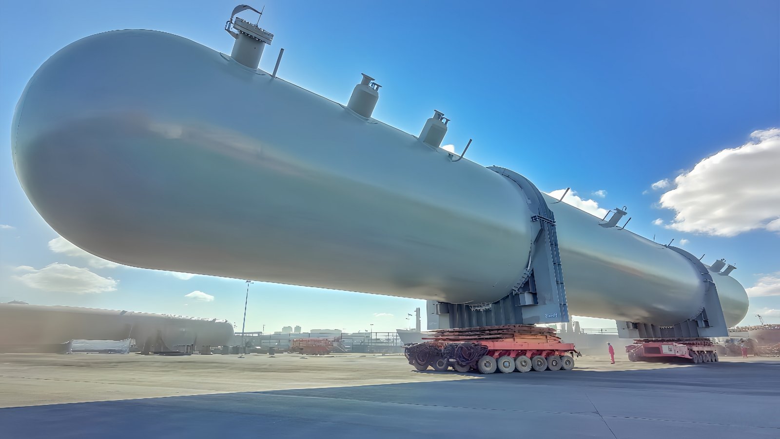
Road and Rail Transport Vessels
Road tankers, rail tank cars, and portable tanks require pressure-rated containment, transport approval, mechanical protection, relief devices, secure piping, filling controls, and periodic inspection. Mobile equipment also experiences vibration, acceleration, braking, and transport loads that differ from stationary vessels.
U.S. requirements for compressed gases in cargo tanks and portable tanks are addressed in 49 CFR 173.315. The applicable transport rules depend on the jurisdiction, tank type, service conditions, and route.
Marine Cargo and Terminal Systems
Ship-based CO2 transport can connect multiple capture sites with offshore or coastal storage hubs. Marine systems may include cargo tanks, loading arms or hoses, vapor return, cargo pumps, refrigeration or pressure-control systems, emergency shutdown, custody metering, and terminal buffer storage.
The International Maritime Organization’s IGC Code provides an international safety framework for ships carrying liquefied gases in bulk. Final marine requirements must be confirmed with the ship designer, class society, flag administration, terminal authority, and project owner.
Pipeline Injection Interfaces
At a receiving terminal, LCO2 may be conditioned, pumped, heated, or pressurized before entering a pipeline or injection system. Buffer vessels help separate intermittent transport schedules from continuous pipeline and storage operations.
In the United States, 49 CFR Part 195 includes requirements for pipeline facilities transporting carbon dioxide. Pipeline and vessel interfaces should be reviewed as one pressure-control system.

Key Design Factors for LCO2 Pressure Vessels
Operating Pressure and Temperature
The design basis should include normal operating pressure, maximum allowable working pressure, design temperature, minimum design metal temperature, startup, cooldown, loading, unloading, blocked-in liquid, loss of refrigeration, fire exposure, and depressurization scenarios.
The lowest credible metal temperature may occur during flashing or depressurization rather than during normal storage. This makes low-temperature material selection and impact toughness especially important.
CO2 Composition and Moisture
Captured CO2 may contain water, oxygen, nitrogen, argon, hydrogen, carbon monoxide, sulfur compounds, or other impurities depending on the capture process. Impurities can change phase behavior, density, corrosion risk, relief calculations, and product specifications.
Moisture control is particularly important because water can contribute to corrosion, hydrate formation, freezing, or operational problems in cold equipment and transfer lines. The vessel design should use an approved CO2 composition envelope rather than assume pure, dry CO2.
Materials and Welding
Material selection depends on design pressure, minimum temperature, thickness, code, impact-test requirements, corrosion assessment, and CO2 composition. The project may require low-temperature carbon steel, stainless steel, nickel-containing materials, forgings, or other specified materials.
Welding procedure qualification should address the selected material group, thickness, heat input, filler metal, post-weld heat treatment if applicable, and required impact toughness. Material certificates, heat-number traceability, weld maps, welder qualifications, and NDT records are key parts of the final data book.
Insulation and Heat Leak
Insulation reduces heat ingress, pressure rise, refrigeration duty, and venting losses. The insulation system should be selected according to storage temperature, vessel size, ambient conditions, moisture protection, fire requirements, maintenance access, and project life.
Buyers should request a heat-leak design basis rather than only an insulation thickness. The outer cladding, vapor barrier, penetrations, supports, and insulation workmanship all affect actual performance.
Filling Ratio and Vapor Space
The vessel must retain enough vapor space for thermal expansion and pressure management. Maximum filling limits should follow the applicable code, transport regulation, operating temperature, and product density. High-level alarms and independent high-high shutdown may be required to prevent overfill.
Pressure Relief and Dry-Ice Risk
Overpressure can result from heat ingress, loss of refrigeration, blocked-in liquid, overfilling, pressure-building systems, external fire, control failure, or transfer operations. Relief philosophy may include pressure safety valves, rupture discs, thermal relief valves, controlled venting, or emergency shutdown.
Trapped liquid between closed valves can experience rapid pressure rise as it warms. Transfer lines, hoses, pump circuits, and isolated vessel connections should be reviewed for thermal relief.
Dry ice can form if pressure drops below the phase boundary during venting, pump suction, unloading, or emergency depressurization. Potential consequences include blocked valves, damaged pumps, unstable flow, measurement errors, and delayed restart. Operating procedures and control logic should limit pressure-drop rates and protect critical equipment.
Loading and Unloading Equipment
The vessel supplier should review the full operating sequence before nozzle positions are frozen. An LCO2 transfer system may include:
- Liquid loading and unloading connections
- Vapor return and pressure equalization
- Transfer pumps and minimum-flow recirculation
- Flexible hoses or loading arms
- Emergency shutdown valves and breakaway couplings
- Level, pressure, temperature, and flow instrumentation
- High-level and low-pressure interlocks
- Sampling, drainage, purging, and cooldown connections
- Thermal relief for trapped liquid sections
Pump suction design is critical because flashing can cause cavitation and unstable unloading. Available net positive suction head, vessel pressure, liquid temperature, line losses, pump type, and minimum operating level should be evaluated together.
Instrumentation and Safety Systems
A typical vessel package may include level transmitters, independent high-level switches, pressure transmitters, temperature sensors, local gauges, relief devices, emergency shutdown valves, gas detection, ventilation interfaces, and alarms.
CO2 is not flammable, but it can displace oxygen and create an asphyxiation hazard, particularly in enclosed, low-lying, or poorly ventilated areas. OSHA’s compressed gas requirements provide general U.S. safety context. Facility-specific ventilation, detection, access control, emergency response, and exposure assessment remain necessary.
Manufacturing and Quality Control
Before fabrication, the manufacturer should review the vessel datasheet, process and instrumentation diagrams, general arrangement, material specification, nozzle schedule, insulation basis, relief interfaces, inspection plan, packing, and delivery route.
A large-scale pressure vessel manufacturer should provide controlled material procurement, forming, welding, NDT, dimensional inspection, pressure testing, coating or cladding, insulation installation, documentation, and export delivery.
Typical Inspection Scope
- Material certificate and traceability review
- Visual and dimensional inspection
- Radiographic or ultrasonic testing where required
- Magnetic particle or liquid penetrant testing
- Impact testing and hardness testing where specified
- Pressure and leak testing
- Relief-device certificate review
- Coating, cladding, and insulation inspection
- Final nameplate and document review
How Should Buyers Evaluate Suppliers?
A reliable supplier should demonstrate experience with low-temperature pressure equipment, code design, material traceability, welding qualification, NDT control, insulation, nozzle-interface review, documentation, and large-equipment delivery.
| Evaluation Area | Strong Evidence | Warning Sign |
|---|---|---|
| Design basis | Complete datasheet and assumptions list | Quotation based only on vessel volume |
| Low-temperature design | Defined MDMT, impact testing, and material basis | Minimum temperature left unclear |
| Welding and NDT | Qualified procedures and project-specific inspection plan | Generic procedures without toughness basis |
| Insulation | Heat-leak calculation and installation controls | Insulation thickness quoted without performance basis |
| Transfer interfaces | P&ID and operating sequence reviewed before nozzle freeze | Generic nozzle layout |
| Documentation | Data-book index agreed before fabrication | Documents treated as optional |
| Compliance | Clear code, approval, inspector, class, or transport route | Described only as a standard tank |
What Buyers Should Prepare Before Quotation
Before requesting a quotation, prepare:
- Storage capacity and required usable volume
- CO2 composition, purity, and water content
- Operating and design pressure
- Operating temperature, design temperature, and MDMT
- Stationary, road, rail, portable, marine, or terminal duty
- Loading and unloading rates
- Expected storage duration and transport frequency
- Insulation and heat-leak requirements
- Filling limits and inventory philosophy
- Nozzle schedule and transfer-system interfaces
- Relief, vent, shutdown, and instrumentation requirements
- Applicable code, jurisdiction, class, or transport approval
- NDT, inspection, pressure testing, and documentation scope
- Delivery destination, road limits, port handling, and site unloading conditions
Common Project Mistakes
Specifying Capacity Without a Phase Envelope
A vessel cannot be selected from cubic meters alone. Pressure, temperature, composition, minimum metal temperature, filling limit, heat leak, and operating scenarios must be defined.
Treating Insulation as a Cosmetic Item
Insulation affects pressure rise, refrigeration duty, venting, and product losses. It should have a defined thermal-performance basis and quality-control plan.
Ignoring Transfer and Trapped-Liquid Scenarios
Many operational risks occur in piping, hoses, pumps, and isolated liquid sections rather than in the main vessel shell. Loading and unloading systems should be reviewed together with the vessel.
Comparing Quotations Before Technical Normalization
A low quotation may exclude insulation, low-temperature impact testing, relief valves, instruments, third-party inspection, transport approvals, documentation, packing, or port delivery. Compare the same technical scope before comparing price.
FAQ
How do LCO2 storage projects use pressure vessels?
They use pressure vessels as buffer and bulk storage between capture, liquefaction, transport, terminal, pipeline, injection, or utilization operations while maintaining the required pressure-temperature conditions.
Why are pressure vessels necessary for LCO2 transport?
They provide certified containment, insulation, pressure relief, filling control, and transfer interfaces that keep liquefied CO2 within its approved operating envelope during road, rail, portable, or marine transport.
Does LCO2 storage require insulated vessels?
Most refrigerated LCO2 storage requires an insulation system to limit heat ingress, pressure rise, refrigeration duty, and venting. The exact design depends on pressure, temperature, vessel size, and project duty.
What causes dry ice in an LCO2 system?
Dry ice can form when pressure falls too far during flashing, venting, unloading, or depressurization. Control procedures should prevent rapid pressure loss and protect valves, pumps, and transfer lines.
What should buyers evaluate in an LCO2 vessel manufacturer?
Buyers should evaluate code capability, low-temperature materials, welding and NDT, insulation performance, transfer-interface review, documentation, regulatory approvals, delivery planning, and after-sales support.
Conclusion
LCO2 pressure vessels form a critical link between carbon capture, liquefaction, transport, terminal storage, pipelines, injection, and utilization. Their design must control phase behavior, low-temperature material performance, heat ingress, filling limits, pressure relief, transfer operations, and project-specific regulatory requirements.
If you are sourcing LCO2 storage tanks, CO2 transport vessels, liquefied-gas storage equipment, heat exchangers, separators, or other custom pressure equipment for CCS, CCUS, industrial gas, marine, terminal, or EPC projects, you can discuss your project requirements with an engineering and manufacturing team. Sharing CO2 composition, storage volume, operating conditions, transport mode, materials, inspection needs, certification route, and delivery terms will support technical communication and fabrication evaluation.