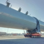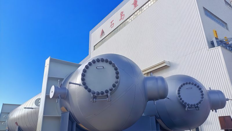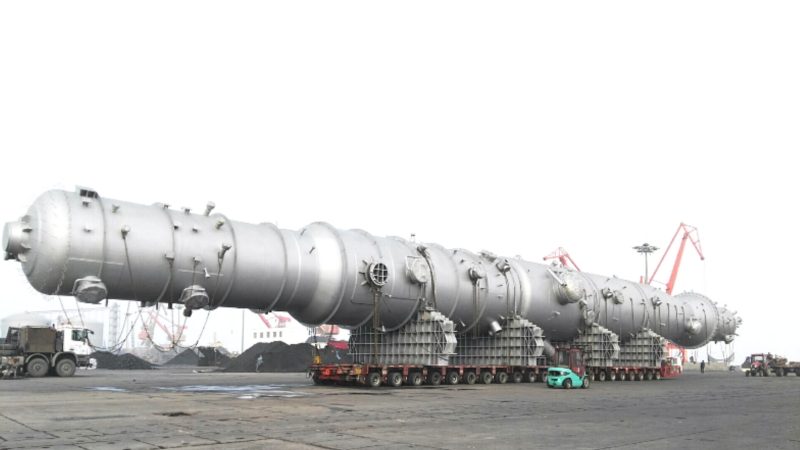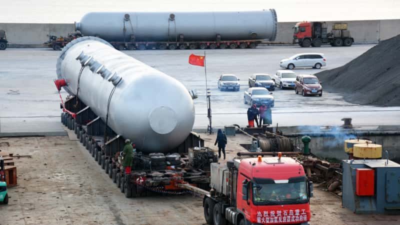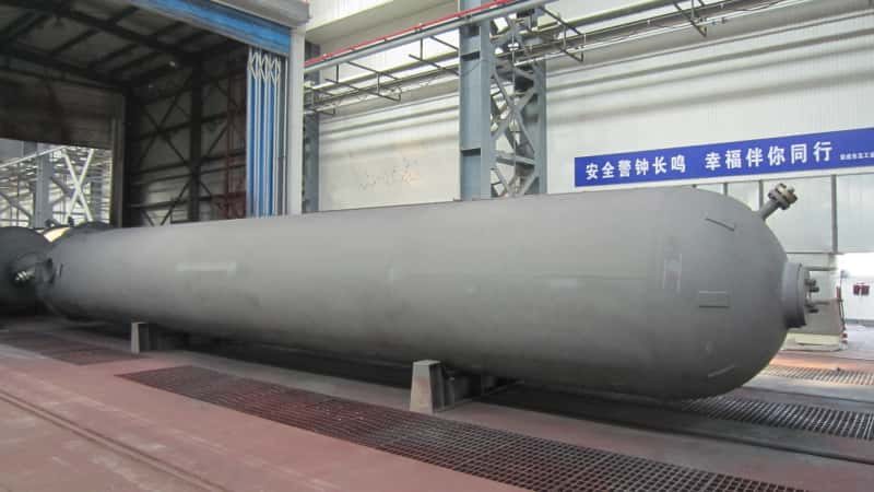

Scaling a hydrogen-to-ammonia plant looks straightforward on a process flow diagram. It rarely is on the ground. Synthesis loop vessels rated at 150–300 bar and 400–500 °C demand materials selection that balances hydrogen embrittlement resistance against nitriding attack — get that wrong and you’re looking at accelerated stress corrosion, unplanned shutdowns, and vessel replacement costs that dwarf the original capital budget. Heat exchangers undersized by even 10–15% on the waste-heat recovery side push energy intensity up sharply, burning through the carbon-reduction case that justified the project in the first place.
Hydrogen-to-ammonia project equipment covers the electrolyzer skids, ammonia synthesis converter vessels, high-pressure heat exchangers, knockout drums, and storage tanks that together form a green ammonia production loop. Key selection criteria include hydrogen embrittlement resistance in Cr-Mo or austenitic-lined pressure vessels, waste heat recovery capacity of 2.5–4.0 GJ per tonne NH3 (depending on loop pressure and catalyst bed staging), and compliance with ASME, PED, or equivalent pressure equipment codes.
What drives the difference between a plant that hits its production target in year one and one that spends the first eighteen months in iterative troubleshooting is not the process license — it’s the mechanical specification and procurement discipline behind each piece of static equipment. The decisions made at the equipment datasheet stage, long before fabrication begins, determine whether the synthesis loop runs at design pressure or limps along at a derated condition that quietly erodes the economics of the entire decarbonization project.
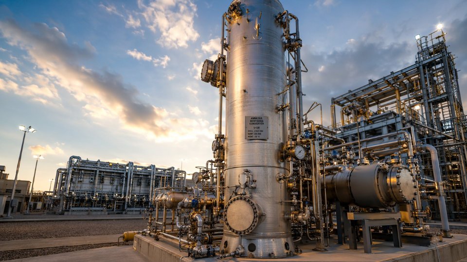
Ammonia Synthesis Converter Design: Pressure Vessel Specifications and Material Selection
The ammonia converter sits at the heart of any Haber-Bosch loop and, by extension, represents the single highest-capital, longest-lead-time vessel in a green ammonia plant. Getting the specification wrong costs you months in redesign or, worse, a premature in-service failure that shuts down the entire synthesis loop.
Operating Envelope and Design Code Jurisdiction
Synthesis converters operate across a fairly wide but well-documented range: 150–300 bar working pressure and 380–520°C, with the specific conditions depending on loop design philosophy, catalyst type, and whether the plant is a grassroots build or a revamp of an existing unit. At these combined pressure-temperature conditions, the vessel moves unambiguously into ASME Section VIII Division 2 or EN 13445 Part 3 territory — neither Division 1 nor any national lightweight standard is adequate. Division 2 demands design-by-analysis rather than the simpler design-by-formula route, which means finite element analysis of nozzle junctions, head-to-shell transitions, and the heavy flange closures that allow catalyst basket removal. EN 13445 follows similar logic with its Category III/IV classification for lethal or high-pressure service. EPC contracts for export projects sometimes specify both codes simultaneously; verify this early because it affects mill certification, weld procedure qualification, and third-party inspector scope before a single plate is ordered.
Hydrogen Embrittlement, Nitriding Attack, and Nelson Curves
High-pressure hydrogen at elevated temperature attacks carbon steel through decarburization — the Nelson curve mechanism. At partial hydrogen pressures and temperatures typical of an ammonia converter, plain carbon steel is simply not viable. The industry default for the pressure-bearing shell is 2.25Cr-1Mo (ASME SA-387 Grade 22), which offers an acceptable Nelson curve margin at most converter operating points. Where hydrogen partial pressure or temperature sits near or above the 2.25Cr-1Mo curve limit, fabricators step up to 3Cr-1Mo-V (vanadium-modified), which provides a meaningfully higher threshold and better resistance to temper embrittlement — relevant because these vessels cycle during startups and shutdowns, not just hold steady state.
Nitriding is a separate and often underweighted threat. Ammonia at high temperature decomposes partially at the catalyst bed and on exposed metal surfaces, driving nitrogen into the steel lattice and forming a brittle iron nitride case. The standard mitigation is an austenitic stainless steel liner — typically 347 or 321 SS — on all internal surfaces that contact the process gas directly. The liner is not a structural member; it carries no pressure load. Its job is purely corrosion and nitriding barrier. Specifying liner thickness, attachment weld detail, and thermal expansion allowance in the data sheet is non-negotiable.
Nelson curves are the primary design tool for material selection in high-pressure hydrogen service above approximately 200°CTrue
API RP 941 (Nelson curves) is the industry-standard reference for selecting steels in hydrogen service at elevated temperature and pressure, and is explicitly referenced in ASME and most EPC project specifications for ammonia synthesis vessels.
Internal Configuration and Fabrication Complexity
Converter internals come in three practical arrangements: axial flow, radial flow, and axial-radial. Axial flow is the simplest mechanically — gas passes straight down through the catalyst bed — but pressure drop is highest, which matters when your loop compressor is a major energy consumer. Radial and axial-radial designs reduce pressure drop by 40–70% compared to pure axial flow (figures depend on catalyst bed depth and gas velocity), at the cost of a considerably more complex internal basket assembly with close-tolerance annular flow channels.
Between catalyst beds, inter-bed heat exchangers — sometimes called “quench exchangers” or “interchangers” — cool the reacting gas to maintain the exothermic reaction within the kinetically favored temperature window. These exchangers are fabricated as removable internal assemblies, and they dictate the minimum internal diameter of the vessel shell, typically driving converters into the 1.8–3.2 m ID range for commercial-scale plants. Fabrication of the basket internals and the shell happen in parallel, but the basket tolerances are tight: misalignment of annular flow channels by even a few millimeters can cause gas bypass, hot spots, and accelerated catalyst sintering.
Wall Thickness, PWHT, and Schedule Impact
Heavy-wall Cr-Mo vessels in this service are not quick to fabricate. Shell wall thickness for a 200-bar, 2.4 m ID vessel in 2.25Cr-1Mo commonly falls in the 120–200 mm range, influenced by design pressure, joint efficiency, corrosion allowance, and whether the designer takes credit for the liner reducing the required corrosion allowance. Weld joint efficiency for Division 2 full-penetration welds with 100% radiographic examination is 1.0, which is where you want to be on a vessel of this consequence.
Post-weld heat treatment is mandatory for Cr-Mo in this thickness range — hold temperatures typically 690–720°C for 2.25Cr-1Mo, with hold times calculated per ASME rules based on thickness. A single PWHT cycle on a large converter shell can occupy a furnace for 24–48 hours, and if the vessel requires multiple weld repairs, additional PWHT cycles cascade directly into schedule slippage. On a 26–36 month fabrication timeline typical for a large converter, PWHT rework is among the top three schedule risk items. Build repair probability into your procurement schedule buffer.
NDE Protocol and Certification Requirements
Examination scope for ammonia converters should include 100% volumetric examination of all Category A and B welds. Phased array ultrasonic testing (PAUT) and time-of-flight diffraction (TOFD) are now the practical standard for heavy-wall Cr-Mo because radiography on wall thicknesses above roughly 75 mm becomes increasingly insensitive to planar defects. Specify both PAUT and TOFD in the inspection and test plan, not as alternatives. Hardness testing of weld metal and heat-affected zones after PWHT is required to confirm the thermal cycle achieved the intended tempering — target hardness for 2.25Cr-1Mo HAZ is typically ≤235 HBW, though the data sheet should reference the applicable WPS-qualified limits. Hydrogen bake-out before hydrostatic testing is good practice to avoid test-induced cracking in the HAZ.
Procurement Checklist: Data Sheet Parameters to Specify
When issuing an RFQ for an ammonia converter, buyers should confirm the following parameters are explicit in the data sheet rather than left to fabricator interpretation:
| Parameter | What to Specify |
|---|---|
| Design pressure and temperature | MAWP at operating T, plus full vacuum rating if required |
| Hydrogen partial pressure | Required for Nelson curve material verification |
| Base material and liner spec | Grade, product form, ASME or EN material standard |
| Internal configuration | Axial, radial, or axial-radial; number of beds |
| NDE method and coverage | PAUT + TOFD scope, RT where applicable |
| PWHT requirements | Temperature range, hold time calculation basis |
| Catalyst loading access | Manway size, location, and internal clearances |
| Fabrication code and division | ASME VIII Div 2 or EN 13445, applicable edition |
| Third-party inspection authority | Stage hold points vs. witness points |
| Delivery condition | Nitrogen-blanketed, desiccant-dried, or other |
Leaving any of these open for “fabricator standard practice” on a vessel of this complexity and value is how plants end up in arguments over scope after award — or discover an undersized nozzle neck only when the catalyst basket arrives on site.
Hydrogen Purification and Conditioning Equipment: Vessels, Adsorbents, and Membrane Units
The synthesis loop in a Haber-Bosch plant is unforgiving about feed gas quality. Catalyst poisoning from trace impurities is cumulative and largely irreversible, so the conditioning train between your hydrogen source and the converter is not a place to cut scope. Understanding what each piece of equipment actually does — and why it exists — is prerequisite knowledge for any procurement engineer specifying this section of a green or blue ammonia facility.
Why Feed Gas Purity Thresholds Are So Tight
Nitrogen and hydrogen entering the synthesis loop must arrive with combined impurity levels typically below 10–50 ppm for species like CO, CO₂, O₂, and H₂O, with exact limits set by catalyst supplier specifications and loop operating pressure. CO and CO₂ poison the iron-based synthesis catalyst by forming surface carbonyls and carbonates. Water causes direct catalyst sintering. Oxygen reacts violently with the hydrogen stream at elevated temperatures and also deactivates catalyst. Methane and argon are inert but accumulate in the recycle loop, diluting partial pressures and forcing higher purge rates — which means higher hydrogen losses and worse energy intensity.
Even 50 ppm CO in the synthesis loop feed can cause measurable catalyst deactivation within weeks of operation.True
Iron-based Haber-Bosch catalysts are well-documented to be sensitive to oxygen-bearing compounds including CO and CO₂; this is a standard design constraint cited in catalyst supplier technical datasheets and ammonia plant engineering literature.
PSA Vessels: Sizing, Cycling Loads, and Fatigue Life
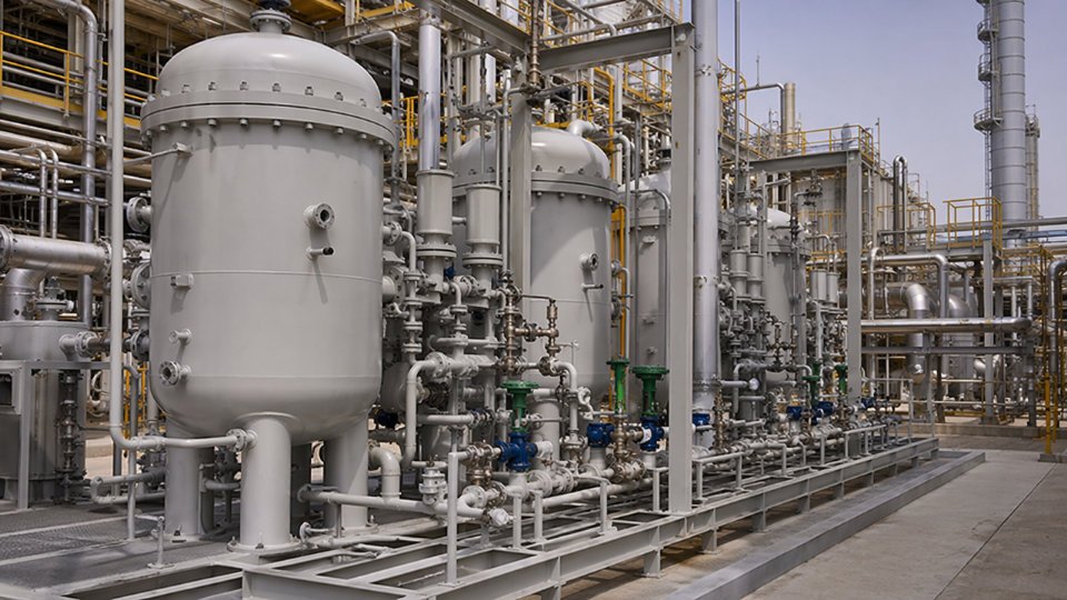
Pressure Swing Adsorption is the dominant hydrogen purification technology for both SMR-based blue ammonia and, increasingly, electrolysis-based green ammonia where electrolyzer outlet hydrogen contains residual moisture, oxygen, and trace organics. PSA vessels cycle repeatedly between adsorption pressure — typically 20–70 bar depending on upstream source pressure — and regeneration at near-atmospheric conditions. A four-vessel to twelve-vessel arrangement is common at commercial scale, with cycle times ranging from 60 seconds to several minutes depending on throughput and purity targets.
The fatigue implication is significant. A vessel cycling five to ten times per hour accumulates millions of pressure cycles over a 20-year service life. ASME VIII Division 2 fatigue analysis, rather than the simpler Division 1 design-by-rule approach, is appropriate for most PSA vessel specifications at this duty. Wall thickness calculations must account for the full pressure range, not just the peak. Adsorbent bed support internals — typically perforated plates with ceramic ball layers or stainless Johnson screens — must be designed to handle bed weight plus the dynamic loading from gas reversal flows during depressurization. Poorly supported beds compact over time, channeling gas and destroying separation efficiency.
Deoxidizer Reactors and Molecular Sieve Dryers
Catalytic deoxidizers sit upstream of PSA where the hydrogen source contains oxygen — most commonly in electrolysis-based green ammonia, because PEM and alkaline electrolyzers produce hydrogen with O₂ concentrations of several hundred to several thousand ppm. These reactors operate at 100–200°C, using a palladium or platinum-promoted catalyst to combust O₂ with H₂. The exotherm is modest but real; vessel design must include thermowell nozzles at multiple bed depths, and a differential pressure indicator across the bed is mandatory for detecting compaction or catalyst fines migration.
Molecular sieve dryers follow the deoxidizer. Vessel design here centers on proper manway sizing for adsorbent changeout — 18-inch minimum for vessels under 1,200 mm diameter, 24-inch preferred above that — and on bed support grid deflection limits under the adsorbent load. Twin-tower configurations are standard to allow one vessel to regenerate while the other adsorbs, and the switching valve arrangement is part of the vessel package scope in most EPC specifications.
Membrane Modules and Interface Vessels
Polymeric or palladium membrane units appear primarily in two places in ammonia plants: hydrogen recovery from synthesis loop purge gas, and, in some green ammonia configurations, as a pre-concentration step ahead of PSA. Operating pressures for polymeric membranes typically run 30–80 bar on the feed side. The critical procurement point is the interface vessel — a knockout drum or buffer vessel on the permeate side that dampens pressure fluctuations and protects the membrane module from liquid slugs. These vessels are relatively modest in size but are frequently under-specified; missing a proper liquid level instrument or an automatic drain on a permeate buffer drum has caused membrane element failures in operating plants.
Blue Versus Green Ammonia: How the Upstream Path Changes Vessel Count
The conditioning equipment scope changes materially depending on your hydrogen source. SMR-based blue ammonia already produces a relatively dry, high-purity hydrogen stream after the shift reactors and CO₂ removal section, so PSA vessels may be the only major conditioning item before the synthesis loop. Electrolysis-based green ammonia requires the full sequence: deoxidizer reactor, dryer, and then PSA — typically three to four additional pressure vessels per train compared to the blue pathway. At a 200-tonne-per-day green ammonia facility, that translates to a meaningful difference in vessel count, adsorbent inventory value, and associated instrumentation scope. Procurement teams specifying green ammonia projects often underestimate this upstream vessel load in early budget estimates.
Fabrication Inspection Milestones for PSA Vessels
For ASME U-stamp PSA vessels, the inspection sequence typically includes: material traceability verification at plate receipt, weld procedure and welder qualification review before fabrication starts, radiographic or ultrasonic examination per UW-11 requirements, hydrostatic test at 1.3 times MAWP (per the 2019 and later ASME VIII Division 1 editions), and pneumatic leak test of nozzle connections and manway flanges. The documentation package — MDR (Manufacturer’s Data Report), NDE reports, material test reports, and hydrostatic test records — is the legal record for the vessel and must be complete before any U-stamp is applied. EPC contractors should require the MDR format to match their document management system requirements in the purchase order, not at delivery.
High-Pressure Heat Exchangers in Ammonia Synthesis: Design Types, Tube Materials, and Thermal Performance
Heat exchangers are neither the most glamorous nor the most discussed equipment category in ammonia synthesis, but they consistently appear on the critical path for procurement and commissioning. A mid-scale green ammonia plant with a 200–500 tonne/day synthesis loop may carry eight to fourteen individual exchanger items, and the combined fabricated weight routinely exceeds that of the converter itself. Lead times of 28–52 weeks for TEMA Class R units in Cr-Mo alloy steel are realistic, depending on forge availability and code witness requirements.
Functional Positions in the Synthesis Loop and Their Thermal Duties
The feed/effluent exchanger — sometimes called the loop economizer — handles the heaviest continuous thermal duty. It preheats cold synthesis gas entering the converter using the hot effluent leaving it, operating at pressures of 150–220 bar and inlet temperatures on the hot side of 380–480°C. Even a 5–8°C degradation in approach temperature here translates directly into higher furnace or electric preheater duty and measurable energy intensity increase per tonne of NH₃.
Inter-bed coolers sit between catalyst beds inside or outside the converter shell, depending on whether the design uses internal or external quench. External inter-bed coolers allow direct maintenance access and independent inspection, which most EPC specifications now prefer for plants above 300 tonne/day. Their pressure ratings match the converter, but thermal shock resistance matters because bed temperatures can swing 40–80°C during load ramp events on variable-renewable-backed green ammonia plants.
Ammonia condensers cool the converter effluent below the dew point to allow liquid ammonia separation. They carry a two-phase condensing duty on the shell side, typically 0.8–1.6 GJ/tonne NH₃ depending on loop pressure and cooling medium. Boiler feed water preheaters recover lower-grade heat — generally below 220°C — but their fouling scenarios are different; scale from BFW side and iron carbide particles from upstream pipework both accumulate here.
Shell-and-Tube Configuration Choices for High-Pressure Ammonia Service
Fixed tubesheet construction minimizes shell-side volume and suits duties where the temperature differential between shell and tube is modest and predictable — typically below 50°C mean metal temperature difference. At higher differentials, the axial stress in the shell can become the limiting factor rather than pressure. U-tube bundles eliminate the differential expansion problem but create a dead-leg at the U-bend that traps liquid ammonia and accelerates stress corrosion cracking if moisture ingress ever occurs — a real risk during shutdown and preservation periods.
Floating-head designs (TEMA Type S or T) add mechanical complexity but give the tube bundle freedom to expand independently. For feed/effluent exchangers operating across a 200°C+ range between startup cold and normal hot conditions, floating-head construction is usually the engineering choice despite its 15–25% cost premium over fixed tubesheet equivalents of equivalent surface area.
Tube Material Selection
| Service Position | Temperature Range | H₂ Partial Pressure | Recommended Tube Material | Key Constraint |
|---|---|---|---|---|
| Feed/effluent exchanger | 200–480°C | 60–140 bar | 2.25Cr-1Mo (SA-213 T22) | Nelson curve compliance; PWHT mandatory |
| Inter-bed cooler | 250–430°C | 60–140 bar | 2.25Cr-1Mo or 304L SS | 304L acceptable if NH₃ concentration 50 ppm in cooling water |
| BFW preheater | 100–220°C | Shell-side low | Carbon steel (SA-179) | Oxygen pitting risk on tube ID; BFW chemistry control critical |
The Nelson curve remains the primary screening tool for hydrogen partial pressure versus temperature combinations. At 140 bar H₂ partial pressure and 450°C, plain carbon steel sits dangerously close to or beyond the carbon steel curve depending on the specific heat, and the operational consequence of getting this wrong is irreversible decarburization and blistering — equipment that cannot be repaired in the field.
2.25Cr-1Mo steel (Grade 22) provides adequate resistance to hydrogen attack at the temperatures and hydrogen partial pressures typical of ammonia synthesis feed/effluent exchangers when properly heat-treated and stress-relieved per applicable code requirements.True
ASME Section VIII Division 1, API RP 941 (Nelson curves), and decades of refinery and ammonia plant operating history confirm Grade 22 as the standard material in this service window, provided post-weld heat treatment is executed within the 690–760°C range specified and hardness limits are verified.
TEMA Class R Requirements and Vibration Analysis
TEMA Class R governs synthesis loop exchangers in most project specifications, and for good reason. The synthesis gas stream — predominantly N₂/H₂ at high velocity — produces flow-induced tube vibration that has caused fatigue failures in plants where baffle spacing was set purely by thermal calculations. Acoustic resonance is a distinct failure mode from fluid-elastic instability, and both need to be checked. Anti-vibration bars at U-bends and intermediate support strips between standard baffles are the practical fixes; they add modest cost during fabrication and avoid expensive bundle replacements in the field.
Vendors should submit a formal vibration analysis report — typically per TEMA Section VI — as part of the data book. EPC buyers who skip this requirement during bid evaluation sometimes find it negotiated away. Recovering it after contract award costs time and occasionally requires bundle redesign.
Ammonia Condenser Configuration
Horizontal orientation with shell-side condensation is the more common layout for water-cooled designs because gravity-assisted drainage of condensate prevents liquid slugging in the shell. Vertical units are used where plot space is constrained or where gravity-drained ammonia recovery to a below-grade separator is preferred. Air-cooled condensers introduce a fundamentally different design discipline — finned tube bundles, motor-driven fans, and ambient temperature sensitivity — and their thermal performance degrades on hot days precisely when some plants are under peak production pressure.
For plants integrated with refrigeration-assisted separation, the condenser also interfaces with a refrigerant circuit. The two-phase flow distribution across multiple tube passes must be modeled carefully; uneven distribution causes some passes to flood while others run partly dry, degrading overall heat transfer coefficients by 20–40% from design values in poorly distributed units.
Fouling Allowances and the Green Ammonia Complication
Standard TEMA R fouling allowances for synthesis gas service sit around 0.00018 m²·°C/W on the tube side. Green ammonia plants fed from alkaline or PEM electrolyzers introduce a variable that traditional fossil-based plants do not face at the same scale: upstream hydrogen purity fluctuations during electrolyzer load cycling can cause fine catalyst dust to migrate from the converter into downstream exchangers when the loop is not fully stabilized. This deposits on tube surfaces and progressively raises pressure drop. Some operators in early green ammonia projects have reported fouling rates two to three times the design allowance in the first operating year before electrolyzer controls were optimized.
Specifying cleanable bundle configurations — removable bundles, adequate shell nozzle sizing for hydraulic cleaning lances — is a low-cost insurance measure that many first-time green ammonia project teams overlook during the value engineering phase.
Inspection and Pressure Testing Protocols
Hydrostatic testing at 1.3× design pressure (per ASME VIII) remains the standard proof test for tube bundles before shipment. Pneumatic testing is sometimes requested when hydrostatic test loads would overstress the supporting structure or when the exchanger cannot be fully dried afterward — ammonia service being a case where residual water is genuinely problematic. Pneumatic testing requires a formal risk assessment and greater exclusion zone; it is not a shortcut and should never be proposed by a vendor as one.
Eddy current testing of finned or bare tubes provides a baseline condition record before commissioning that is invaluable for future in-service comparison. EPC buyers should specify pre-shipment eddy current on 100% of tubes for feed/effluent and inter-bed exchangers; selective spot-check protocols on lower-risk positions like BFW preheaters are acceptable. The inspection records, tube maps, and mill certificates for all pressure-retaining materials should be bound into a single data book delivered before — not after — mechanical completion.
Ammonia Separator and Flash Vessels: Sizing Criteria, Internals, and Low-Temperature Material Requirements
The ammonia separator sits immediately downstream of the synthesis loop condenser, and its job is deceptively simple: pull liquid ammonia out of a high-pressure recycle gas stream before that gas returns to the converter. In practice the vessel operates at a genuinely awkward intersection — pressures ranging from 130 to 200 bar depending on loop design, and wall temperatures that can reach -33°C at the liquid ammonia boiling point under worst-case depressurization or cold ambient startup. Most pressure vessel fabricators build plenty of high-pressure vessels, and plenty of low-temperature vessels. Fewer have routine experience with both simultaneously, which is exactly why this equipment category deserves careful attention during vendor qualification.
Process Function and the Dual Extreme Problem
Under normal steady-state operation, the separator receives a gas-liquid mixture from the condenser at something like -10°C to -25°C and 150–180 bar. The liquid ammonia drops out and is routed to let-down, while the recycle gas — primarily unreacted N₂, H₂, and inert argon or methane — returns to the recycle compressor. The problem for vessel design is that the combination of high pressure and low temperature narrows the acceptable material window considerably. Carbon steel that would be adequate at 150 bar in a warm service loses ductility fast once you drop below -29°C; a brittle fracture at that pressure is catastrophic.
Low-Temperature Toughness: Materials and Code Requirements
ASME Section VIII Division 1 governs most of these vessels in global EPC practice, and the UCS-66 impact exemption curves are the starting point for MDMT determination. For a separator designed to -33°C MDMT, normalized carbon steel is typically exempted only at very low thicknesses — once wall thickness climbs above roughly 25–38 mm at operating pressure, you need supplemental Charpy V-notch impact testing or a tougher material altogether.
Common material choices in practice: 304L or 316L austenitic stainless steel is used when corrosion or contamination is a concern and cost allows; 3.5% Ni steel (ASTM A203 Grade E) is the workhouse choice for the -50°C to -40°C range and is more weldable than higher-nickel grades; 9% Ni steel (ASTM A353 or A553) is reserved for cryogenic storage applications below -100°C and is rarely necessary in synthesis loop separators unless the plant uses refrigerated ammonia recovery at sub-atmospheric conditions. Impact test acceptance criteria under ASME are typically 27 J (20 ft-lb) lateral expansion average at the MDMT, verified on weld metal and HAZ samples as well as base plate.
9% Ni steel is required for standard ammonia synthesis loop separatorsFalse
9% Ni steel is engineered for cryogenic service below -100°C. Ammonia separator MDMTs in synthesis loops typically fall in the -33°C to -40°C range, where 3.5% Ni steel or low-temperature tested carbon steel grades are the standard cost-effective choice. Specifying 9% Ni steel here adds material and welding cost without process justification.
Vapor-Liquid Separator Sizing Methodology
Separator diameter is set by the Souders-Brown (K-factor) approach: the allowable vapor velocity equals K × √[(ρ_L − ρ_V)/ρ_V], where K typically falls in the range of 0.04–0.08 m/s for high-pressure vertical vessels without mist eliminators, dropping to 0.03–0.06 m/s when you account for elevated gas density at 150+ bar. At those pressures, gas density can reach 80–120 kg/m³, which compresses the allowable velocity range significantly compared with low-pressure separators — an engineer accustomed to atmospheric gas separators who applies a K-factor appropriate to low-density gas will underestimate entrainment badly.
Liquid hold-up volume is sized for 3–10 minutes of residence time depending on the level control scheme. Tighter level control with fast-responding valves allows the lower end; plants with slug-prone condensers or intermittent refrigeration cycles should budget toward the upper end to prevent liquid carryover into the recycle compressor — an event that causes mechanical damage within seconds.
L/D ratios for high-pressure vertical separators typically run 3:1 to 5:1. Going shorter saves shell weight but compromises liquid-vapor disengagement height; going longer creates foundation load problems and increases the shell course count, adding weld joints and inspection cost.
Mist Eliminator Internals
A wire mesh demister pad is the default for clean ammonia service — knitted 304 or 316 stainless wire at 100–150 mm thickness, installed with adequate clearance from the gas outlet nozzle. The limitation is blinding: if the ammonia condensate carries oil contamination from compressor carry-over (a real operational hazard in reciprocating compressor loops), wire mesh plugs and pressure drop climbs fast. Vane-pack separators handle higher liquid loading and are more resistant to fouling, but they cost more and require careful orientation relative to the inlet distributor. Cleanout access — a flanged manway sized to physically remove the internals — is non-negotiable in the fabrication specification. Plants that omit this detail during procurement routinely spend 12–40 hours of downtime cutting and re-welding nozzle flanges when internals need inspection.
Flash Vessels and Let-Down Stations
Once liquid ammonia leaves the separator, it undergoes pressure reduction from synthesis pressure (150–200 bar) down to refrigerated storage pressure (typically 15–20 bar for intermediate flash, then near-atmospheric for cold storage). Each let-down stage involves two-phase flashing, and the combination of high velocity, liquid droplets, and sometimes dissolved gas makes erosion at valve outlet and downstream pipe bends a serious concern. Hard-faced trim valves, minimum 10-pipe-diameter straight runs downstream of let-down valves, and pipe wall thickness allowances for erosion are standard practice.
The flash vessel itself is a lower-pressure vessel by synthesis standards — ASME Division 1 at 20–25 bar is typical — but it still requires low-temperature material qualification because flashing cools the stream. Adiabatic flash from 180 bar to 20 bar can cool the ammonia liquid to near its boiling point at that pressure, potentially reaching -20°C to -28°C depending on inlet temperature. Specifying standard carbon steel at this point without checking MDMT has caused cracking failures in older plant retrofits.
Certification and Inspection Requirements
Third-party inspection during fabrication rather than at final hydrostatic test alone is the standard expectation for Class 1 synthesis loop vessels. Weld joint efficiency for longitudinal and circumferential seams should be specified at 1.0, requiring 100% radiographic or ultrasonic examination — this is not optional on vessels combining high pressure and low-temperature service. Post-weld heat treatment (PWHT) is required for carbon and low-alloy steel above thickness thresholds defined in ASME UCS-56; verify that the heat treatment procedure covers the actual weld joint geometry, not just a coupon. Hydrostatic testing at 1.3 × design pressure with documented test temperature above the MDMT plus 17°C (per ASME) must be witnessed and documented, with mill certificates, NDE records, and impact test reports packaged as part of the final data book for regulatory submission.
Ammonia Storage Tanks and Spheres: Atmospheric Refrigerated Versus Pressurized Design Selection
Storage equipment is rarely the glamorous part of an ammonia project conversation, but it is frequently the item that controls plot space, capital allocation, regulatory approval timelines, and ultimately project schedule. Getting the storage strategy wrong at front-end engineering can mean rebuilding a civil foundation or renegotiating an insurance policy. The decision between refrigerated flat-bottom tanks and pressurized spheres or bullets deserves more rigorous treatment than a simple capacity cutoff rule.
The Two Fundamental Storage Strategies
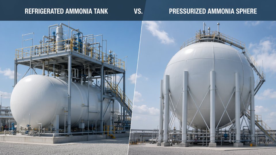
Atmospheric refrigerated storage keeps liquid ammonia at approximately -33°C and near-ambient pressure. These tanks are designed to API 620 Annex R or BS 7777, both of which mandate full-containment or double-wall construction at meaningful scale. The inner tank is typically 9% nickel steel — the same material class used in LNG service — because it maintains adequate toughness and ductility at -33°C without becoming brittle. The outer tank or bund is carbon steel or prestressed concrete depending on the containment philosophy. Between the two shells, perlite fill remains the most common insulation system for large tanks, though polyurethane foam and cellular glass each appear in specific project contexts. Perlite is inert, non-combustible, and performs reliably over decades; its drawback is the annular space it requires and the purging discipline needed during construction and maintenance. Cellular glass has better compressive strength for foundation-loaded areas but costs more per unit volume of insulation.
Pressurized storage operates at ambient temperature — typically 10°C to 40°C depending on site climate — with design pressures in the range of 14 to 17 bar for spheres and horizontal bullets. These vessels fall under ASME Section VIII Division 1 or Division 2, and the material is generally carbon steel with appropriate low-temperature impact testing at the lower end of ambient conditions. No cryogenic metallurgy is required, which simplifies fabrication and procurement for smaller vessels.
Capacity Thresholds and Selection Logic
The threshold is not a single number; it depends on throughput, plot availability, and risk zoning requirements. As a practical range, pressurized bullets or spheres are economically competitive up to roughly 1,000 to 2,000 tonnes of storage per vessel. Above that range, the steel mass required for pressure containment grows disproportionately with volume, and the capital cost per tonne of stored ammonia shifts decisively in favor of refrigerated tankage. Large fertilizer complexes and export terminals — where storage inventories of 10,000 to 50,000 tonnes are common — almost universally use refrigerated flat-bottom tanks, typically in banks of two or more for operational continuity.
Smaller distributed facilities, agricultural retailers, and mid-scale industrial users frequently choose pressurized horizontal bullets in the 50 to 500 tonne range. These can be shop-fabricated, hydrostatically tested, and transported to site on flatbeds, which compresses schedule compared to a site-built refrigerated tank requiring months of civil work, erection, welding, and hydro-pneumatic testing.
9% nickel steel is required for atmospheric refrigerated ammonia storage inner tanks at -33°CTrue
At -33°C, standard carbon steel loses toughness and becomes susceptible to brittle fracture. 9% Ni steel maintains a fine-grained ferritic-martensitic microstructure that retains impact toughness at this temperature, which is why API 620 Annex R and BS 7777 both specify it for the inner tank in full-containment refrigerated ammonia storage.
Refrigerated Tank Design Features That Drive Fabrication Scope
Full-containment tanks include a suspended deck — a thin aluminum or stainless steel membrane hung from the roof structure — that sits on the liquid surface and significantly reduces the boil-off gas (BOG) volume above the liquid. BOG management matters operationally and commercially. Boil-off rates on well-insulated modern tanks run roughly 0.04% to 0.08% of stored volume per day, but that figure is sensitive to insulation condition, ambient temperature variation, and fill level. The BOG system typically consists of a compressor that returns vapor to the process or a small flare, sized per the maximum heat ingress scenario rather than average conditions.
Pressure and vacuum relief valve sizing follows API 2000, accounting for fire case heat input, pump-in filling rates, and thermal breathing. Under-sizing the relief system is not a conservatism question — it is a mechanical integrity question. Refrigerated tanks operating at slight positive pressure (typically 5 to 50 mbar gauge) are sensitive to vacuum events during rapid drawdown, and the vacuum relief valve must be sized to prevent tank shell inward buckling, which can be catastrophic and is not repairable in the field.
Pressurized Sphere Fabrication Considerations
Spheres in industrial ammonia service range roughly 10 to 25 meters in diameter, with the larger end approaching 2,000 to 3,000 tonne capacity. The geometry creates real inspection challenges: all welds on a sphere are on a curved surface, which complicates radiographic and ultrasonic examination setups compared to a cylindrical shell. Leg support welds are high-stress details and require full volumetric examination. ASME U-stamp certification applies, and the authorized inspection agency must be embedded in the fabrication process, not called in at the end.
Weld joint efficiency assumptions under ASME Section VIII Division 1 directly affect shell thickness — and therefore material cost and weight. Moving to Division 2 with full radiography can reduce wall thickness by 15% to 25% depending on design pressure, which is worth evaluating on large spheres where the steel tonnage is significant.
Safety and Environmental Integration
Secondary containment is not optional at any meaningful scale. For refrigerated tanks, the bunded area volume must typically contain 110% of the largest tank volume, and the bund floor and walls need chemical-resistant lining because liquid ammonia will attack unprotected concrete over time. Leak detection systems — point detectors, open-path infrared, or electrochemical sensors depending on the detection philosophy — must be positioned accounting for ammonia’s vapor density relative to air (0.59, meaning it rises) and local wind patterns.
Vapor dispersion modeling under credible release scenarios influences equipment spacing, bund wall height, and sometimes the choice between refrigerated and pressurized storage in sites with constrained safety exclusion zones. Pressurized storage releases tend to generate immediate flashing and aerosol formation; refrigerated tank failures, while rarer, can release large liquid inventories into the bund. Neither scenario is acceptable without credible detection and isolation response.
The fabrication and delivery contrast is operationally significant for project scheduling. Refrigerated flat-bottom tanks are site-built: foundations, annular plate welding, shell course erection, roof construction, and insulation installation typically take 12 to 24 months for large tanks. Pressurized bullets and spheres allow shop fabrication under controlled quality conditions, with delivery to site as complete or near-complete assemblies. For projects under time pressure, that difference can determine whether a facility commissions on schedule or carries months of demurrage risk.
Nitrogen Production and Feed Gas Conditioning Equipment for Haber-Bosch Integration
Nitrogen is the other half of ammonia, yet in green ammonia project scoping it often gets treated as an afterthought until the synthesis loop design is nearly complete. That sequencing mistake costs time and money. The nitrogen supply train — air separation, compression, moisture knockout, ratio control, and inerts purging — constitutes a discrete procurement package with its own licensor relationships, lead times, and pressure vessel scope. Getting it right early prevents the kind of feed-gas quality excursions that silently destroy catalyst beds.
Nitrogen Purity: Why 10 ppm Is Not Arbitrary
Oxygen and moisture content in the nitrogen feed must each stay below roughly 5–10 ppm entering the synthesis loop. The Haber-Bosch catalyst — typically promoted iron or, in newer designs, ruthenium — oxidizes irreversibly when oxygen spikes occur. Even brief excursions above 20–30 ppm O₂ can reduce catalyst activity measurably, and the damage is cumulative. Moisture compounds the problem: water at synthesis pressures forms ammonium compounds and accelerates corrosion in the Cr-Mo converter shell. Plants running on electrolytic hydrogen face an additional risk because electrolyzer upsets can carry oxygen traces downstream if guard beds are undersized. Specifying purity at the battery limit — not at the ASU outlet — forces the package boundary to account for the conditioning steps between them.
Oxygen contamination above 20–30 ppm in the nitrogen feed causes irreversible catalyst deactivation in iron-based Haber-Bosch convertersTrue
Promoted iron catalysts oxidize under oxidizing conditions at synthesis temperatures; unlike sulfur poisoning, which may be partially reversible, iron-oxide formation in the active sites is not recoverable without catalyst replacement.
Air Separation Unit Options and Loop Integration
Cryogenic ASUs dominate at capacities above roughly 500–1,000 Nm³/h of nitrogen because they deliver the lowest oxygen residual (routinely below 1 ppm) and are well-suited to continuous baseload operation. Below that threshold, pressure swing adsorption (PSA) becomes cost-competitive and simpler to operate, though it typically delivers 99.5–99.999% N₂ purity depending on adsorbent bed design and cycle time. Membrane nitrogen generators sit below PSA on purity — rarely below 100 ppm O₂ — making them unsuitable for direct synthesis loop feed without a downstream polishing step. The interface between the ASU battery limit and the synthesis loop is where specification gaps appear most often: the ASU licensor quotes delivery pressure, the synthesis contractor specifies inlet conditions, and nobody explicitly owns the conditioning vessels in between.
Compression Vessels, Knockout Drums, and Wet Nitrogen Service
Nitrogen must be compressed from near-atmospheric ASU delivery pressure to synthesis loop inlet pressure, which ranges from roughly 100 to 220 bar depending on loop design. Reciprocating compressors are standard for this service. Each compression stage needs an interstage knockout drum to remove condensed moisture — wet nitrogen at pressure causes stress corrosion and erosion in carbon steel drums unless the material is upgraded to 316L stainless or the drums are epoxy-lined. Design pressure for these vessels should include a margin above the maximum allowable working pressure of the compressor relief setting, typically 10–15% above the stage discharge pressure.
Feed Gas Mixing and Ratio Control
The 3:1 H₂:N₂ stoichiometric ratio entering the converter must be held tightly — deviations of even a few percent shift the equilibrium and reduce single-pass conversion. Ratio control uses flow ratio controllers on both feed streams, with a surge drum or pulsation dampener on the nitrogen compressor outlet to prevent pressure oscillations from propagating into the analyzer signal. These dampening vessels are modest in size but must be rated to full loop pressure, and their inspection access provisions often get omitted in early P&IDs.
Inerts Purge System Vessels
Argon and methane accumulate in the synthesis loop because they are neither consumed nor condensed efficiently. The purge stream — typically 1–5% of recycle flow — is withdrawn from the high-pressure recycle loop and processed through a membrane recovery unit that returns 80–95% of the hydrogen content back to the loop. The pressure vessel scope here includes the purge gas drum upstream of the membrane unit, which operates at full loop pressure, and the permeate receiver, which operates at a much lower pressure determined by the membrane driving force. Both require proper pressure relief and drain provisions. Specifying these vessels late in a project often creates a bottleneck because they fall outside the main converter package and outside the ASU scope — a procurement gap that should be assigned explicitly in the equipment responsibility matrix.
Managing the Vendor Interface
ASU packages from specialist licensors come with their own compression, cold box, and controls. Custom pressure vessels — knockout drums, surge vessels, purge drums — are sourced separately from fabricators capable of ASME Section VIII Div. 1 or Div. 2, PED, or equivalent certification. The interface document between the ASU licensor and the vessel fabricator needs to define composition, temperature, pressure, and flow pulsation data at every handoff point. Without a clear interface specification, the vessel fabricator may undersize nozzles or select inadequate corrosion allowances for the actual service fluid rather than the assumed clean gas.
Equipment Fabrication Standards, Certification Pathways, and Quality Control Requirements for Global EPC Projects
Getting the certification pathway wrong on a pressure vessel order for an ammonia synthesis loop is not a paperwork inconvenience — it is a project-stopping event. Vessels that arrive on site without the correct stamp, registration, or conformity mark cannot be legally installed in most jurisdictions. On a green ammonia project with a fixed commissioning window tied to a power purchase agreement, that translates directly into liquidated damages.
Applicable Design and Fabrication Codes by Market
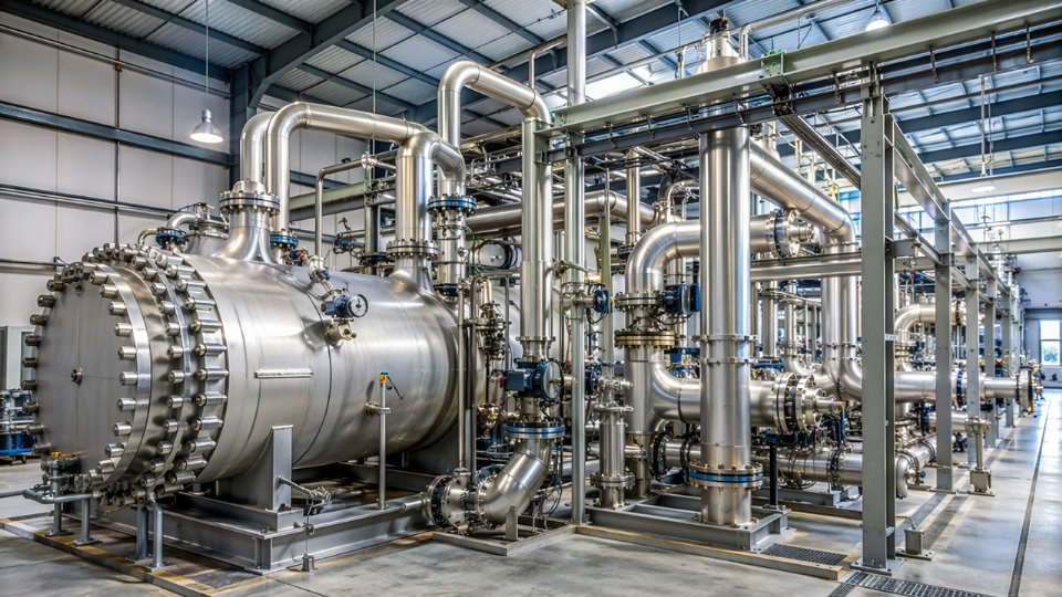
Three code families dominate international ammonia plant procurement. ASME Section VIII Division 1 covers the bulk of general-service vessels; Division 2 is specified for high-pressure ammonia converters and loop heat exchangers where the alternative design rules allow thinner walls at the cost of more rigorous fatigue and fracture analysis. Most North American projects and a large share of export work destined for LNG or chemical hubs in Southeast Asia and the Middle East defaults to ASME. EN 13445 paired with the Pressure Equipment Directive 2014/68/EU governs equipment placed on the European market; Category III and IV classification applies to virtually all high-pressure ammonia service equipment above roughly 10 bar with hazardous fluid, which pulls in the most demanding conformity assessment routes. GB 150 applies to China-domestic projects; fabricators holding only GB 150 authorization cannot self-certify for ASME or PED markets without separate authorization — a point that catches procurement teams off guard when they shortlist Chinese fabricators without checking the actual stamp scope.
ASME Stamps, National Board Registration, and What They Actually Require
The U-stamp covers Division 1 vessels; the U2-stamp covers Division 2. Obtaining either requires an ASME survey of the fabricator’s quality system, documented design review capabilities, and demonstrated production controls — not a one-time audit but an active authorization renewed on a three-year cycle. National Board registration (the “NB” stamp) is separate and required whenever the vessel must be officially recorded for jurisdiction tracking in the United States and Canada. For a fabricator in any country exporting to North American projects, both the U-stamp and NB registration are typically mandatory. Verify the fabricator’s current authorized scope at ASME’s online directory before issuing a purchase order; authorizations lapse, and a fabricator may hold a U-stamp but not a U2-stamp, which is the relevant credential for converter vessels operating above 200 bar.
CE Marking Under PED: Conformity Assessment Modules
For Category III and IV equipment — the categories that cover thick-wall Cr-Mo ammonia converters and high-pressure shell-and-tube exchangers in European projects — the conformity assessment modules are not interchangeable. Module G (individual unit verification) is common for one-off or low-volume custom vessels and involves a Notified Body reviewing each unit independently. Module B+F (type examination plus production quality assurance) suits fabricators with a repeatable product range. Module H (full quality assurance) requires the highest level of Notified Body involvement in the fabricator’s quality management system. EPC specifications should state the required module explicitly; leaving it open invites the fabricator to propose the least burdensome route, which may not satisfy the end-client’s insurance requirements.
Any fabricator with a CE mark on their nameplate qualifies to supply Category IV PED equipment.False
CE marking alone does not specify the conformity assessment module used. A Category IV vessel requires a Notified Body-supervised module (B+F, G, or H). Procurement teams must verify which module was applied and which Notified Body issued the certificate — the certificate number should be traceable on the Notified Body's public register.
Third-Party Inspection: Role, Scope, and Practical Limits
TPI bodies — Lloyd’s Register, Bureau Veritas, TÜV SÜD, SGS, APAVE — are not interchangeable on every project. Some client specifications or insurance underwriters require a specific body; confirm this before the fabricator mobilizes their chosen inspector. The TPI inspector’s role on a heavy ammonia vessel package typically covers: witnessing hydrostatic testing (normally at 1.25× to 1.5× design pressure depending on code), reviewing material test reports (MTRs) for compliance with the purchase order material specification, witnessing or reviewing positive material identification (PMI) checks on alloy components, and issuing an inspection release note (IRN) that authorizes shipment. The IRN is the physical gate to logistics; without it, the freight forwarder should not accept the vessel. Plan TPI witness points into the fabrication schedule from the outset — a fabricator that books the hydrostatic test without confirmed TPI availability will either wait (adding weeks) or conduct the test without witness (creating a conformance dispute).
Material Traceability and the Documentation Package
For Cr-Mo alloy vessels — 2.25Cr-1Mo or 3Cr-1Mo are the typical grades in high-pressure ammonia service — the documentation package is substantial. MTRs must be traceable from the mill certificate through heat number to the specific plate or forging used in each identified weld zone. PMI with XRF or OES instruments is standard for all alloy nozzles and weld overlays; the PMI record is tied to the weld map. Welding procedure specifications (WPS) and procedure qualification records (PQR) must cover each weld joint configuration and position used in production. Welder performance qualification records (WPQR) must be current. Retaining this package for the vessel’s operating life — which on an ammonia plant is commonly 20 to 30 years — is the owner’s obligation, but the fabricator must deliver it complete at shipment.
Non-Conformance Patterns in Heavy-Wall Cr-Mo Fabrication
Three failure modes appear repeatedly during shop inspection of thick-wall Cr-Mo vessels. Post-weld heat treatment (PWHT) hardness exceedances — typically discovered during Brinell hardness surveys on completed welds — indicate insufficient hold time or temperature uniformity in the furnace, and require re-PWHT with re-survey, adding one to three weeks. Hydrogen-induced cracking in the heat-affected zone (HAZ) occurs when preheat is inadequate or hydrogen-controlled electrodes are mishandled; TOFD or PAUT examination is the detection method, and repair welding on a near-complete vessel is expensive. Dimensional deviations at forged nozzle attachment areas — particularly flush nozzles or heavy-wall nozzles on converter shells — arise from insufficient machining control on the forgings; they trigger fit-up rework that disrupts weld sequence and re-qualification requirements.
The Vendor Document Requirement List and Schedule Reality
EPC contractors issue a Vendor Document Requirement List (VDRL) that specifies every document the fabricator must submit, the required submission timing, and the review cycle. For a high-pressure ammonia vessel package, a VDRL commonly runs to 40 to 80 line items: drawings, calculations, material certificates, weld maps, WPS/PQR records, PWHT charts, NDT reports, hydrostatic test records, coating inspection reports, nameplate rubbings, and the final data book. Fabricators that have not previously supplied to major EPC contractors frequently underestimate the documentation workload. A realistic estimate is that documentation preparation and EPC review cycles consume 15 to 25 percent of total fabrication schedule on a complex vessel; factor this into the delivery commitment before the purchase order is signed, not after the first document submission is rejected.
Equipment Lead Times, Modularization Strategies, and Supply Chain Risk Management for Green Ammonia Projects
Schedule risk on a green ammonia project almost never originates in civil works or piping. It originates in the fabrication queue for heavy-wall pressure vessels. Understanding that single fact changes how a competent EPC project manager structures the entire project timeline.
Realistic Lead Times and What Drives Them
Ammonia synthesis converters — thick-wall, Cr-Mo vessels rated to 150–300 bar with internal catalyst baskets and liner systems — carry fabrication lead times of 18–30 months from purchase order to ex-works delivery. The wide range reflects vessel diameter, wall thickness, the shop’s backlog at the time of order, and availability of certified plate or forged shell rings in the required alloy grade. A 1,000 t/d plant converter is not a standard catalog item. It is a discrete, one-off fabrication project inside the vessel shop, competing against refinery hydrocracker reactors and other high-specification vessels.
High-pressure shell-and-tube heat exchangers in the synthesis loop — feed-effluent exchangers, waste heat boilers, trim coolers — run 12–18 months, depending heavily on whether seamless tube material in 321H stainless or duplex alloy is in stock or requires a mill run. Refrigerated flat-bottom ammonia storage tanks are site-built and sit in the 24–36 month window, gated by insulated inner tank steel delivery, outer tank concrete progression, and roof installation sequencing. PSA vessel sets for hydrogen purification typically fall in the 10–16 month band, though a multi-vessel set with identical geometry often qualifies for batch fabrication, which can compress schedule if planned early.
Synthesis loop converters for large green ammonia plants carry lead times that frequently exceed 24 months from purchase order to delivery.True
Heavy-wall Cr-Mo vessels above 200 bar require specialized plate or forging supply, progressive heat treatment, multi-stage PWHT, and third-party witness inspection hold points that accumulate across a fabrication period that routinely runs 18–30 months for large-diameter units. This is consistent with typical refinery-grade reactor fabrication experience.
Early Procurement and Letter of Intent Structure
If synthesis loop converters and high-pressure exchangers are not ordered at or before FEED completion, they will land on the critical path — and they will stay there. The practical mechanism is a letter of intent issued to the shortlisted fabricator while the detailed engineering package is still being finalized. The LOI reserves shop capacity and material allocation in exchange for a partial payment, typically 5–15% of the estimated contract value. It should include a firm slot-hold period of 60–90 days, a preliminary vessel datasheet sufficient for plate or forging procurement, and a clear escalation clause covering steel price movements.
Procurement teams sometimes resist this approach because it commits budget before final approval. The consequence of waiting is a 4–8 month schedule slip on the critical converter delivery, which on a project with $2–5 million per month in carrying costs is a straightforward calculation.
Modularization: Where It Genuinely Reduces Risk
Modular fabrication works best for the hydrogen conditioning train — PSA skids, membrane unit frames, buffer vessel assemblies, and associated piping and instrumentation. Assembling these in a controlled shop environment allows concurrent hydrostatic testing, instrument loop checks, and third-party inspection access that is far harder to achieve on a congested site. Typical module weights run 40–150 tonnes; standard heavy-lift transport handles this range without special permits in most jurisdictions.
Pre-assembled heat exchanger bundles for the synthesis loop offer similar benefits. A bundle inspected, cleaned, and leak-tested at the shop arrives site-ready and avoids the field re-work that often results from site installation under weather or schedule pressure.
What modularization does not solve is the fundamental lead time of the heavy pressure vessels themselves. Those vessels define the schedule, and no modularization strategy substitutes for ordering them early.
Geopolitical and Logistics Risk in Vessel Supply
Sourcing large synthesis converters from lower-cost fabricators in East Asia versus regional European or North American shops involves a genuine cost-schedule tradeoff. Fabrication cost differentials of 20–40% are plausible depending on vessel complexity and labor content, but transport of a vessel weighing 300–800 tonnes requires heavy-lift vessel chartering, port crane capacity verification at the destination, and overland transport routing that may require road survey and permit lead times of 3–6 months in some regions. A fabrication cost saving can be partially or fully consumed by logistics cost and schedule risk if the receiving port cannot handle the lift or the road to site has a bridge weight restriction.
The prudent approach is to conduct a transport feasibility study — vessel weight, dimensions, port draft, crane ratings, road survey — before awarding to an Asian fabricator on price alone. This is not a theoretical risk. Projects have absorbed significant remediation costs when a converter arrived at port and the available crane was undersized.
Spare Parts Philosophy
Spare internals for ammonia separators — demister pads, vortex tube sets, internal baffles — should be included in the main vessel supply contract rather than purchased as a separate procurement action. Lead times for replacement internals from the original fabricator can run 6–12 months; having one set of critical internals on the shelf at commissioning prevents a forced outage during the first operating year. For heat exchanger bundles in the synthesis loop, a spare bundle for the most thermally loaded exchanger is worth evaluating at FEED stage. Catalyst basket inspection spares — thermowell assemblies, basket support rings — are low-cost relative to an unplanned shutdown and should be included as standard.
Digital Tools That Actually Reduce Rework
3D model integration for nozzle orientation verification has become standard practice on EPC projects and catches interference errors before fabrication is locked in — errors that would otherwise require weld repair or nozzle relocation at substantial cost. Automated vendor document register tracking reduces the administrative burden on the project team and provides early warning when a fabricator’s documentation submission falls behind a milestone that triggers a witness inspection hold point. Digital inspection records tied to the vessel tag number create a complete quality dossier that is increasingly required by owners, insurers, and regulatory bodies in export markets.
Frequently Asked Questions About Hydrogen-to-Ammonia Plant Equipment
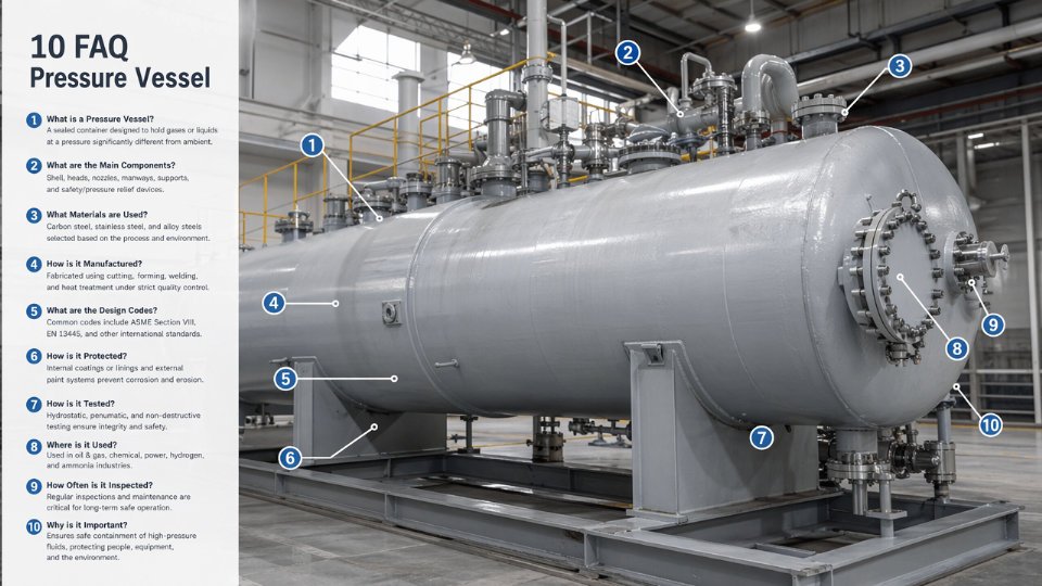
What is the most critical pressure vessel in an ammonia synthesis loop, and why does it have the longest lead time?
The ammonia synthesis converter is the single most schedule-critical item in the entire plant. It combines extreme operating conditions — typically 150–300 bar and 400–500°C depending on loop design and catalyst system — with large forged shell sections that must be sourced from a short list of qualified heavy forge shops globally. The shell forgings alone can require 20–40 weeks from a confirmed order, and that clock does not start until the forge shop has an approved drawing package and material certification. After forging comes sequential machining, nondestructive examination, weld procedure qualification, post-weld heat treatment, and final shop hydrostatic testing. Each step has hold points requiring third-party inspection witness signatures before the next operation begins. Total fabrication time for a large converter — say, one serving a 500-tonne-per-day synthesis loop — commonly runs 18–30 months from purchase order to delivery, depending on forging slot availability, NDE backlog, and whether the vessel requires an internal austenitic liner. Procurement teams that treat the converter as a mid-project item routinely find it sitting on the project critical path six months before mechanical completion.
What design code applies when a project must export ammonia-service pressure vessels to both European and North American markets?
For vessels that will be installed in Europe, the Pressure Equipment Directive (PED 2014/68/EU) applies, and the vessel must carry CE marking under a Notified Body. In North America, ASME Section VIII Division 1 or Division 2 with a U-stamp or U2-stamp is the standard commercial requirement, and NBIC National Board registration is expected for jurisdictions that mandate it. Dual certification is achievable — many fabricators hold both ASME authorization and a quality system audited to EN 13445 — but the buyer must specify this requirement at inquiry stage, not after award. Specifying dual code compliance late adds cost through rework on documentation packages and may require additional NDE scope to satisfy both code interpretations simultaneously. For vessels in hydrogen or ammonia service, always confirm that the selected Notified Body has specific experience with high-pressure hydrogen-service equipment; not all do.
How does hydrogen embrittlement affect alloy selection for high-pressure synthesis loop vessels?
Standard carbon steel pressure vessels are unsuitable for ammonia synthesis converter shells operating above roughly 200 bar in high-temperature hydrogen service without alloy upgrading.True
The Nelson curves in API 941 define temperature-pressure limits for carbon and low-alloy steels in hydrogen service; exceeding these limits causes irreversible decarburization and hydrogen attack, which destroys mechanical integrity.
The Nelson curves in API 941 are the starting point. For synthesis loop operating conditions, 2.25Cr-1Mo-V (Grade 91 variant) is the most widely specified shell material — it offers high hydrogen partial pressure resistance, adequate creep strength at 450–500°C, and a proven track record in ammonia and hydroprocessing service. Where hydrogen partial pressures or temperatures push toward Nelson curve boundaries, an austenitic stainless steel (typically 304L or 321) internal liner is added. The liner isolates the low-alloy ferritic shell from the process gas while the shell carries the pressure load. Welding the liner to the shell requires qualified overlay procedures and careful attention to thermal expansion mismatch, particularly at nozzle penetrations.
What distinguishes refrigerated ammonia storage from pressurized storage, and which conditions favor each?
For inventory above roughly 1,000–2,000 tonnes, refrigerated flat-bottom tanks operating near atmospheric pressure at approximately –33°C are almost always the economic choice. The steel tonnage in the tank itself is far lower than an equivalent pressurized sphere, and refrigeration operating costs are offset by the reduced vessel wall thickness. Pressurized spheres and bullets — typically rated 15–25 bar — are practical for smaller inventories, for sites where refrigeration utility supply is unreliable, or for temporary or mobile applications. Applicable codes differ: refrigerated tanks are commonly designed to BS EN 14620 or API 625, while pressurized spheres follow ASME Section VIII or equivalent. Site conditions matter too: seismic zone, soil bearing capacity, and the availability of boil-off gas handling infrastructure all influence the final selection.
Can GB 150-certified Chinese fabricators supply vessels for international EPC ammonia projects?
Yes, subject to qualification. Many large Chinese fabricators hold current ASME U-stamp and U2-stamp authorizations, meaning their quality systems have been audited by an ASME Authorized Inspection Agency and they are permitted to manufacture vessels to ASME code with the stamp applied. The GB 150 certification alone is not accepted as equivalent by most international EPC contracts or by ASME jurisdictions. The practical path is to specify ASME or PED compliance at inquiry, confirm the fabricator’s current stamp status through the ASME online directory, and appoint a recognized TPI firm — Lloyd’s, Bureau Veritas, TÜV, or equivalent — to witness all hold points independently. That TPI presence is the insurance policy against documentation gaps and interpretation differences that can surface during final dossier review.
What documentation must be in the final vessel dossier for an ammonia plant pressure vessel?
A complete dossier typically includes: material test reports (MTRs) traceable to each heat and lot of plate, forging, and fitting used; weld maps identifying every weld seam with the applicable qualified weld procedure specification (WPS) and procedure qualification record (PQR); NDE reports for all required radiographic, ultrasonic, and magnetic particle or dye penetrant examinations; post-weld heat treatment charts with time-temperature records for every heat cycle; the hydrostatic or pneumatic test certificate with witnessed sign-off; nameplate data sheet matching the stamped nameplate; National Board Form U-1 or equivalent data report; and the Authorized Inspector’s signed certification. For vessels with internal liners or cladding, the bond test or shear test records belong in the dossier as well. Missing any of these items at project handover triggers delays in commissioning authorization — inspectors and insurers will not sign off on an incomplete package.
How long does it take to fabricate a large ammonia storage sphere, and what drives the schedule?
A sphere in the 500–2,000-tonne capacity range typically requires 12–22 months from order to field completion, depending heavily on steel plate procurement lead time, sphere diameter, and the field welding program. Plate procurement for large-diameter spheres — often 25–50 mm thick high-strength carbon or low-alloy steel — can take 4–8 months alone if the steel mill order book is full. Fabrication of the petal sections in the shop, followed by transport and field assembly, adds another 4–8 months. Field welding is sequential and each circumferential and meridional seam requires radiographic or TOFD examination before the next weld proceeds; TPI hold points at each stage are non-negotiable. Hydrostatic testing of the completed sphere in the field, followed by post-test inspection and drying, adds 4–8 weeks at the end. Starting sphere procurement after the synthesis loop equipment is a schedule mistake that projects make more often than they should.