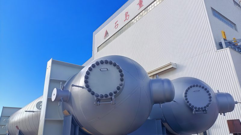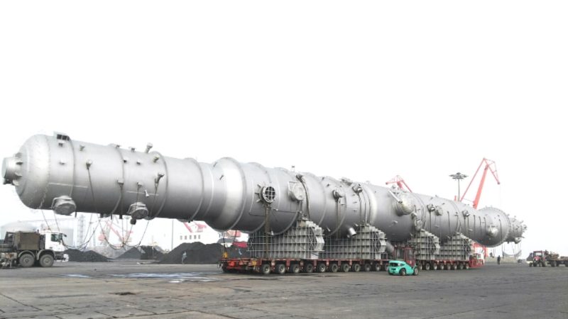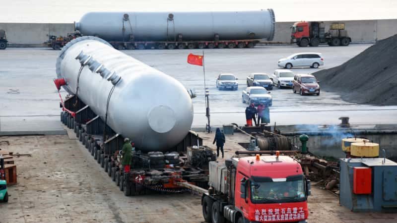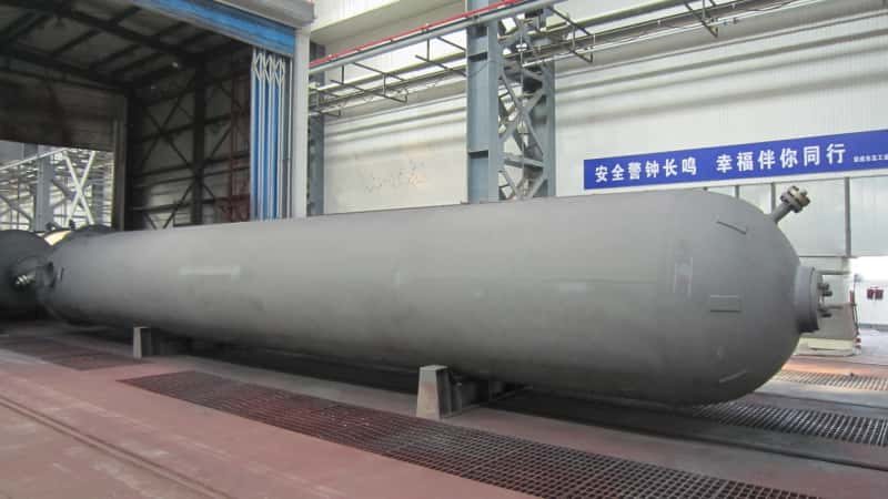

Pressure vessel packages arrive at the battery limit of an EPC project and nobody has documented exactly what the vendor owns versus what the site contractor picks up — then the hydrostatic test certificate sits in a Shanghai freight office while the interconnecting piping crew stands idle waiting for a flange-face confirmation that was never formally assigned. That handover gap, which looks like a paperwork problem, routinely costs a project two to four weeks of schedule float and drags in liquidated damages clauses that were written for exactly this scenario. Procurement managers who have lived through one of these disputes rarely make the same boundary ambiguity mistake twice.
Battery limits in a custom pressure vessel package define the precise physical, documentary, and contractual boundary between the vendor’s scope and the EPC contractor’s site scope. For a skid-mounted separator or vessel package, that boundary typically falls at the first flange face on each process nozzle, includes the vessel body, supports, local instruments, primer coat, hydrostatic test certificate, and mill certificates, and is formally established through P&ID tie-in points, equipment datasheets, and a vendor document register listing deliverable document types.
What makes this deceptively complex is that the boundary is never purely physical. A vendor can deliver a code-stamped vessel in perfect condition under CIF Incoterms and still trigger a contract dispute because the VDR listed thirty-two document deliverables and only twenty-nine cleared the FAT review before the vessel left the fabrication shop. Understanding where the vessel ends and the project begins — across hardware, inspection records, and delivery milestones simultaneously — is the real engineering and procurement skill this article unpacks.
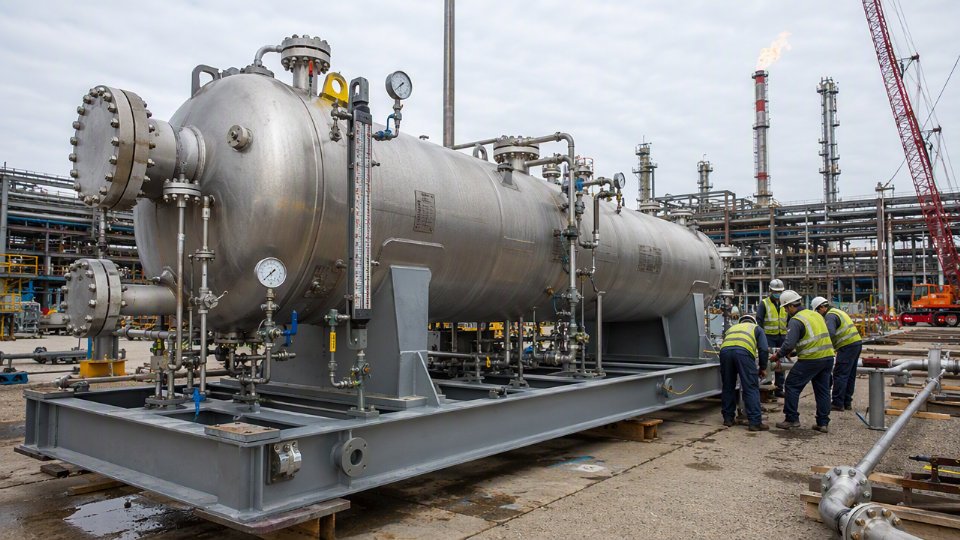
Physical Battery Limits: Where the Vessel Package Ends at Every Nozzle, Support, and Skid Edge
The single most disputed line in any pressure vessel purchase order is not price — it is where the vendor’s hardware responsibility stops. Get this wrong in the PO and you will spend the back half of the project arguing over who supplies the first flange, who owns the saddle anchor bolts, and whether the access platform was ever in scope to begin with. None of those arguments are cheap.
The First Flange Face Rule
Standard industry practice, codified in most EPC vendor package specifications, is that the vendor’s physical scope terminates at the face of the first mating flange on every connection — process nozzles, instrument nozzles, manways, vents, and drains alike. “First flange face” means the raised face or flat face of the flange that is welded to or forged integral with the vessel nozzle neck, machined to the dimensional standard (ASME B16.5 for Class 150 through Class 2500 service in inch-based projects, EN 1092-1 for metric PN-rated systems), and pressure-tested as part of the vessel. The bolts, gasket, and the mating flange on the connecting pipe belong to the field installation contractor. That boundary sounds simple. In practice, projects specify it three different ways across the P&ID, the equipment datasheet, and the nozzle schedule, and the three documents sometimes disagree. The nozzle schedule, stamped and signed as a vendor drawing, should govern.
Support Structures: What Is In Scope and What Sits Below the PO Line
Saddle supports for horizontal vessels, leg supports and base plates for vertical vessels, and lug supports welded to the shell are all vendor scope — they are designed to the vessel’s weight, wind, and seismic loading and cannot be separated from the pressure part design without re-engineering the whole thing. The skid base frame on a packaged unit is also vendor scope. What falls outside the vendor’s battery limit: anchor bolts, leveling shims, grout beneath the base plate, foundation pocket sleeves, and the civil foundation itself. A vendor who quotes anchor bolts as “by others” without stating it explicitly in the PO has set up a delay at installation. Specify it in writing.
Attached Appurtenances: A Working Comparison
| Item | Typical Vendor Scope | Typical Exclusion |
|---|---|---|
| Insulation support rings / clips | Included | Insulation material and cladding |
| Lifting lugs (permanent) | Included | Rigging equipment and spreader bar |
| Davit arm for manway cover | Included when specified | Davit arm foundation bracket on structure |
| Nameplate and stamping | Included | Third-party witness fees unless contracted |
| Earthing / grounding boss | Included | Earthing cable and ground grid |
| Internal demister pad or tray | Included when on datasheet | Replacement internals after FAT |
| External painting, primer coat | Included per paint spec | Topcoat if applied at site |
The Skid Edge as a Legal Boundary
On a skid-mounted separator or filter package, the physical edge of the structural skid frame is the battery limit for all interconnecting piping, instrument tubing, cable tray, and conduit. That boundary must appear on a dimensioned general arrangement drawing — the skid boundary drawing — which becomes a contract document. Any pipe spool, junction box, or tubing bundle that crosses the skid edge and runs to a field tie-in point is field installation scope. If the GA drawing is not issued before the PO is signed, expect a change order within six months.
The skid boundary drawing has no contractual standing unless it is listed in the vendor document register and referenced in the PO terms.True
A drawing that exists but is not contractually incorporated can be disputed or superseded. EPC project controls standard practice ties physical scope to VDR-listed, revision-controlled documents.
Platforms and Access Steelwork: The Persistent Grey Zone
Integrated platforms — those welded or bolted to the vessel shell or skid frame at the vendor’s shop — are generally vendor scope when they appear on the certified general arrangement drawing and the platform steel is included in the vessel’s certified weight. Platforms designed as separate structural modules, grouted to a concrete plinth, or requiring field splice connections to a building structure fall into civil or structural scope and should be explicitly excluded in the PO’s scope matrix. The failure mode when this is not resolved is a platform that arrives from the vendor, cannot be installed without field modifications, and generates an RFI that delays mechanical completion by three to six weeks.
Shell-and-Tube Heat Exchangers: Two Independent Boundary Points
A shell-and-tube exchanger has at least four process nozzle connections — channel-side inlet and outlet, shell-side inlet and outlet — and each first flange face is an independent battery limit point. Vendor scope also covers expansion joints (when the thermal analysis requires a bellows), floating head covers on U-tube and floating-head designs, and the tube bundle pull space requirement, which must be dimensioned on the GA drawing so the EPC civil team can plan adequate maintenance clearance. The tube bundle itself, including all tubes, tubesheets, baffles, and tie rods, is vendor scope through FAT completion. Post-FAT tube bundle re-rolling or re-sealing during commissioning is a grey zone best resolved by specifying a tube-to-tubesheet joint acceptance criterion in the datasheet before manufacture begins.
Instrument and Electrical Battery Limits on Custom Vessel Packages
The physical boundary at the flange face is usually settled quickly. The instrument and electrical boundary is where projects bleed money during commissioning — technicians on-site arguing about who owns the thermowell, the impulse line, the junction box terminal, or the first conduit run. Getting this right on paper before the purchase order is signed is not a formality; it directly determines whether your FAT closes on schedule and whether your site pre-commissioning team walks into clarity or chaos.
Defining the Instrument Battery Limit from the P&ID
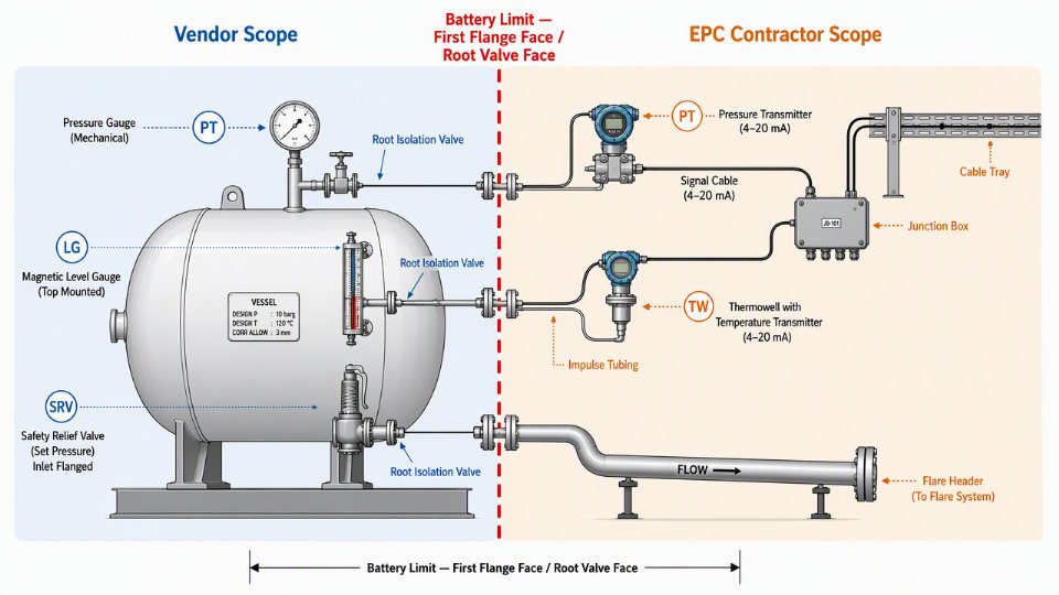
The P&ID tie-in point is the governing reference, not verbal agreement. For a typical custom vessel package, vendor scope covers locally mounted instruments — pressure gauges, dial thermometers, level gauges (glass or magnetic), safety relief valves, and their root isolation valves. Everything mounted directly on the vessel nozzle or its stub connection belongs to the vendor. Transmitters, remote indicators, control signal cables, and impulse tubing beyond the first root valve face are EPC contractor scope unless the purchase order states otherwise in writing.
This distinction matters operationally. A pressure transmitter left off the vendor BOM because “it was assumed EPC would supply it” creates a procurement gap that typically surfaces at FAT, adding two to six weeks to closure depending on lead time for the specific instrument model and process rating.
VFOI and VFVI Categories in the Instrument Index
The instrument index should carry a supply category column for every tag on the vessel package. Two categories appear most often in EPC project documentation:
VFVI (Vendor-Furnished, Vendor-Installed): The vessel manufacturer procures the instrument, mounts it, hooks up the root valve, and confirms it appears on the certified general arrangement drawing. Pressure gauges and level gauges on separator packages almost always fall here.
VFOI (Vendor-Furnished, Owner-Installed): The vendor procures and ships the instrument loose with the vessel package — transmitters are a common example when the EPC wants a specific control system-compatible model — but site installation is EPC scope. The instrument index must flag these explicitly, and the packing list must match, or instruments arrive at port and disappear into a warehouse.
A simple decision table helps at the bid stage:
| Instrument Type | Typical Category | Installed By | Cable/Tubing By |
|---|---|---|---|
| Pressure gauge | VFVI | Vessel vendor | N/A |
| Level gauge (magnetic) | VFVI | Vessel vendor | N/A |
| Safety relief valve | VFVI | Vessel vendor | EPC (outlet to flare) |
| Pressure transmitter | VFOI or EPC-furnished | EPC | EPC |
| Thermowell + transmitter | VFVI thermowell / VFOI transmitter | Split — document it | EPC |
Safety Relief Valve Scope and Compliance Risk
The SRV sits on the vendor’s nozzle. The vendor installs it, torques the inlet flange, and provides the discharge flange face as the battery limit. Inlet piping back-pressure calculations are vendor responsibility up to that face. Everything downstream — discharge pipe to the flare header, any back-pressure compensation — is EPC scope.
The vessel vendor is responsible for SRV outlet piping routing to the flare header in a standard EPC package.False
Standard battery limit practice places the SRV discharge flange face as the vendor boundary. Piping from that flange to the flare header is EPC contractor scope. Misassigning this creates OSHA PSM and PED compliance gaps when relief path design lacks a single accountable party.
Document the discharge boundary explicitly in the SRV datasheet and on the P&ID. Vague language here creates real regulatory exposure — no relief system can have an undefined design responsibility split.
Electrical Battery Limit for Motor-Driven and Heat-Traced Equipment
When the vessel package includes a motor-driven agitator, a pump, or electric heat tracing, the vendor’s electrical scope ends at the terminal box. Cable routing from that terminal box to the motor control center, conduit installation, earthing conductor runs, and MCC connection — all EPC scope. The terminal box itself should be vendor-mounted and labeled; wiring inside it, EPC.
Heat tracing deserves a separate line in the scope matrix. Vendor scope typically covers the tracing element bonded to the vessel surface and the connection box. Power supply cable routing, thermostat controller location, and circuit breaker assignment belong to the EPC electrical team.
Local Instrument Panels and Junction Boxes
When the vendor package includes a local instrument panel (LIP) or junction box, the wire termination point inside that enclosure becomes the battery limit. Define in the purchase order whether the vendor performs full loop checks or only continuity checks before shipment. Loop checks require a signal source and confirm end-to-end function; continuity checks confirm only that wires are connected and unbroken. The difference in commissioning risk is significant — a vessel arriving with only continuity checks confirmed means the EPC site team performs first loop check on-site, adding time and potential rework.
The instrument battery limit must appear in three documents simultaneously: the individual instrument datasheet, any reference in the cause-and-effect matrix that touches a vessel-mounted device, and the vendor document register. If these three are not aligned, you will find the discrepancy at the worst possible time — during pre-commissioning, with the project schedule already under pressure.
Surface Treatment, Insulation, and Fireproofing Scope Boundaries for Pressure Vessel Packages
Coating and insulation scope is where RFQs go vague and budgets quietly bleed. A vessel arrives on site with bare carbon steel supports, no insulation rings, and a primer system incompatible with the EPC’s specified finish coat — and now you have field rework measured in weeks, not days. Defining this boundary precisely in the purchase order costs almost nothing; resolving it after FAT can run 3–8% of the original vessel package value depending on vessel size, environment class, and how far along site construction has progressed.
Shop-Applied Surface Treatment: What the Vendor Owns
Surface preparation to Sa 2.5 per ISO 8501-1 is standard vendor scope for carbon steel pressure vessel packages, essentially without exception. The coating datasheet — issued by the EPC or the end client and attached to the purchase order — must specify the primer type, the required dry film thickness (DFT), and the acceptance test method. Epoxy zinc-rich primers are typical for onshore chemical and refinery service, where they provide sacrificial cathodic protection at a DFT of roughly 50–75 µm per coat. Inorganic zinc silicate is specified for more aggressive environments — coastal, offshore, or high-humidity sites — and requires stricter surface cleanliness because zinc silicate adhesion fails fast on a poorly prepared substrate.
Holiday testing (DC spark or wet sponge, depending on DFT) confirms coating continuity before the vessel leaves the shop. This test result belongs in the vendor’s quality dossier. If the coating datasheet does not call it out explicitly, the vendor may omit it and not be wrong — they simply followed the document. That is a procurement error, not a fabrication defect.
Intermediate and Finish Coats: Shop vs. Field Application
Whether finish coats are vendor or EPC scope depends on project strategy, not on any universal rule. For offshore and coastal packages, shop-applied full coating systems — primer plus intermediate plus finish coat — are common because controlled shop conditions produce better adhesion and film build than field application in a marine environment. For onshore grassroots projects with phased construction, EPC teams often prefer to apply finish coats in the field to avoid transit damage and ensure color consistency with the surrounding installation. Whichever approach applies, the purchase order must state it explicitly, because the vendor’s quote will almost certainly include only primer unless finish coats are specifically listed in scope.
A pressure vessel vendor's standard scope typically includes only shop primer unless intermediate and finish coats are explicitly listed in the purchase order.True
Industry practice and standard quotation conventions place only surface preparation and primer in vendor base scope; finish coat application is a variable that depends on project-specific coating specifications and must be explicitly contracted.
Insulation Support Rings: A Battery Limit Item Routinely Missed
Insulation stand-off rings — welded to the vessel shell at intervals matching the insulation cladding design — are fabricated and installed by the vessel manufacturer before shipment. They are a vendor scope item. The problem is that roughly half the RFQ datasheets seen in practice do not mention them, either because the insulation design is not yet complete at inquiry stage or because the thermal engineer and the procurement team are working from different document revisions. When rings are omitted, the insulation contractor arrives on site, cannot attach cladding without damaging the primer, and raises a variation order against the EPC. The fix — retrofitting rings on a vertical vessel that is already positioned on its foundation — costs far more than having the fabricator weld them in the shop. Confirm ring spacing, material, and weld details in the vessel datasheet before issuing the PO.
Fireproofing Interface: Surface Prep Is Vendor Scope, Application Is Not
Passive fireproofing of skid base steel and vessel saddle supports is civil and structural EPC scope, applied in the field by a specialist contractor. The vessel vendor’s obligation stops at delivering the correct surface condition for fireproofing adhesion — typically Sa 2.5 preparation and a compatible primer coat specified in the fireproofing material’s application data sheet. If the vendor applies an epoxy primer that the intumescent fireproofing manufacturer explicitly excludes from its approved substrate list, the fireproofing contractor will blast it off and reprime. Document this interface in both the vessel coating specification and the fireproofing specification, and confirm primer compatibility in writing during HAZOP or pre-FAT review — not during site construction.
Export Preservation and Packing Scope
For ocean-freight shipments, nozzle blanks (full-face gasket and bolted blind flange, or plastic caps for low-pressure nozzles), desiccant bags inside the vessel, and moisture-barrier wrapping for internals are standard vendor scope. Whether timber crating or open-frame skid packing meets ISPM 15 heat-treatment requirements for wood packaging is sometimes left ambiguous between vendor and freight forwarder. Assign it in the purchase order. The cost difference between compliant and non-compliant packing is small; the delay when a shipment is quarantined at the destination port is not.
Color Coding, Labeling, and Weld Map Markings
RAL or Munsell color reference for finish coats, stainless steel tag plates with stamped or engraved equipment tag numbers, and weld map markings on the vessel shell are all vendor scope deliverables. They need to be confirmed in the PO because last-minute color changes or tag plate specification revisions after shop priming require rework that the vendor is entitled to charge for. Weld maps, in particular, link to NDE records in the quality dossier — any post-fabrication change to shell marking can create traceability questions during third-party inspection.
Inspection, Testing, and Certification Battery Limits: What the Vendor Delivers vs. What the EPC Witness
Scope disputes rarely surface during welding. They surface at the FAT table when the owner’s inspector arrives expecting witnessed hold points that the vendor’s ITP never listed. Getting the inspection and certification boundary into the PO — not the post-award meeting — is the only way to avoid that argument.
Mandatory Vendor-Scope Inspection and Testing
The vessel fabricator owns a defined baseline of inspection regardless of what any EPC specification adds on top. That baseline, for an ASME Section VIII Div.1 carbon or alloy steel vessel, includes dimensional inspection against the approved fabrication drawing, hydrostatic pressure testing at 1.3 × MAWP (or the applicable multiplier per code edition), and NDE per the approved weld map — typically radiographic testing (RT) or ultrasonic testing (UT) on longitudinal and circumferential seams, with magnetic particle testing (MT) or liquid penetrant testing (PT) on nozzle attachment welds and structural attachments. For any pressure-retaining component in an alloy material — 316L stainless, Duplex 2205, Inconel-clad — positive material identification (PMI) is vendor scope, applied to base materials and weld deposits before any post-weld heat treatment closes access.
For PED 2014/68/EU projects destined for European installations, the equivalent framework substitutes or overlays the ASME requirements. Category III and Category IV vessels under PED carry the highest risk classification and require a Notified Body to conduct a conformity assessment of the design, production, and final inspection. Category III covers most gas-service pressure vessels above modest volume-pressure thresholds; Category IV applies to the most hazardous fluid groups and design configurations. The vendor arranges the Notified Body, carries the cost, and delivers the Declaration of Conformity plus CE nameplate marking as contract deliverables — not optional add-ons.
TPI Agency: Who Arranges It, and Who Pays
Third-party inspection is always paid by the vessel manufacturer on ASME U-stamp jobsFalse
On standard commercial ASME U-stamp fabrication, the Authorized Inspector (AI) from a National Board-accredited inspection body is part of the manufacturer's certification overhead and is vendor-paid. However, on national oil company or owner-directed TPI programs — common in Middle East, West Africa, and Southeast Asian EPC projects — the owner nominates and separately contracts the TPI agency, and that cost sits outside the vessel price. The distinction must be stated in the PO.
Owner-nominated TPI typically adds 1–3% to the effective project cost for the vessel scope, depending on inspection intensity, travel requirements, and the number of shop visits. Remote surveillance with document review only sits at the lower end; full resident inspector coverage during critical weld stages sits at the upper end. The PO must state explicitly which model applies and who reimburses vendor-side coordination time — an afternoon escorting an inspector through a busy fabrication shop is not free.
Hold Points, Witness Points, and Review Points
These three terms are not interchangeable and treating them as such causes real schedule damage. A hold point requires the nominated party’s physical sign-off before work proceeds — fabrication stops. A witness point means the party is notified and expected to attend, but work may continue after a defined standby period (commonly 24–72 hours, stated in the ITP) if the party does not appear. A review point requires only document submission and approval; no shop attendance is needed.
A typical ITP structure for a carbon steel process separator looks like this:
| Activity | Vendor | TPI / AI | Owner |
|---|---|---|---|
| Material receiving and PMI | Perform | Review | Review |
| Fit-up inspection before welding | Perform | Witness | Review |
| NDE (RT/UT on seams) | Perform | Hold | Witness |
| PWHT time-temperature chart | Perform | Review | Review |
| Hydrostatic pressure test | Perform | Hold | Hold |
| Final dimensional inspection | Perform | Witness | Witness |
| Nameplate and marking review | Perform | Hold | Review |
The ASME Authorized Inspector holds the U-stamp certification process and must be present at the hydrostatic test — that is non-negotiable under Section VIII rules. The U-1 data report, signed by the AI and the manufacturer, is a mandatory battery limit deliverable. No U-1, no completed handover.
Pre-Shipment Inspection as the Certification Handover Event
PSI is the physical close of the vendor’s inspection battery limit. It covers final external dimensional check, paint film thickness readings against the approved coating spec, nozzle flange face protection (foam inserts, blind flanges, or plywood covers as specified), nameplate legibility, and packing condition adequate for the nominated Incoterms mode — whether FCA at the factory gate or CIF at destination port.
Who attends PSI matters. Owner representatives, the nominated freight forwarder, and TPI all have legitimate interests. The PSI completion package — typically a signed PSI report, final dimensional record, packing list with bundle weights and dimensions, and the full vendor document register (VDR) submission — constitutes the documentary handover that triggers release for shipment and, in many contracts, the final payment milestone. If the VDR is incomplete at PSI, the shipment should not leave. That point is worth making explicit in the subcontract.

Vendor Document Register (VDR) as the Documentation Battery Limit in EPC Projects
Every physical boundary discussion eventually lands here: the VDR. Once the nozzle schedule is agreed and the coating scope is written into the PO, the documentation package becomes the final — and often most contentious — battery limit in a pressure vessel supply contract. Miss a document, submit it in the wrong format, or let the review cycle run uncontrolled, and you will stall mechanical completion on a project where every day of delay carries real liquidated damages exposure.
What the VDR Actually Is
The VDR is a contractual register — not a wish list — that enumerates every document the vessel vendor must submit, indexed by document code, title, revision status, review category, and submission date tied to explicit project milestones (purchase order issue, fabrication start, FAT, final inspection). Review categories matter enormously in practice. “Approved for Construction” (AFC) documents gate fabrication; submitting the wrong category by mistake has caused vendors to start welding on drawings still under review, generating expensive rework when comments come back. “For Information” (FI) documents — spare parts lists, O&M manuals — don’t gate fabrication but are still contractual deliverables with defined due dates.
A typical pressure vessel package VDR for an EPC project will contain somewhere between 15 and 40 line items, depending on vessel complexity, the applicable code (ASME VIII Div.1, PED 2014/68/EU, GB 150), and the owner’s documentation philosophy. Core items almost always include the general arrangement (GA) drawing, nozzle schedule, bill of materials, pressure vessel calculation report, weld map and NDE procedures, material test reports (MTRs) for pressure-retaining components, hydrostatic test report, inspection and test plan (ITP), coating procedure with DFT records, and the U-1 data report or CE Declaration of Conformity. Add a spare parts list and an O&M manual, and you have the irreducible minimum. Some EPC contractors also require a lifting and rigging procedure, a preservation and storage manual, and a packing list with net and gross weights — all of which should be explicit VDR line items, not verbal agreements.
Review Cycles and Schedule Impact
Document review runs in cycles — typically three: Issued for Approval (IFA), Issued for Construction (IFC), and As-Built. Each cycle carries a review period that realistically runs 15–25 working days per cycle depending on the owner’s internal routing complexity and the number of disciplines required to comment (process, structural, I&E, HSE). That means a full three-cycle review consumes 45–75 working days minimum before as-built documentation is closed out — a block of time that must appear explicitly on the project schedule at PO signature. It rarely does. When it isn’t written in, the vendor gets blamed for delays that are actually the result of a review queue sitting in the owner’s engineering office.
A 15–25 working-day document review period per cycle is standard practice on international EPC pressure vessel packages.True
This range reflects common contractual terms seen in oil and gas and petrochemical EPC projects globally, consistent with EPCM industry norms where multi-discipline reviews, PMC routing, and client approvals all contribute to cycle duration.
As-Built Package as a Payment Trigger
The as-built documentation package is not administrative housekeeping. In most EPC contracts it is a defined milestone that releases the final payment retention — commonly 5–10% of the vessel package value. The as-built is only closed after final inspection and pre-shipment inspection (PSI) sign-off; no reputable EPC contractor releases final payment on a document package that still carries open comments. Define this explicitly in the PO. “As-built issued within 30 days of FAT completion” is a workable formulation. “As-built submitted at project closeout” is not — it creates ambiguity about when that clock starts.
Format Requirements Prevent Late Rework
Native CAD files in DWG or DXF, 3D models in STEP or IFC format, and archival-quality PDF/A — these format requirements must be in the PO, not raised at handover. A vendor who modeled in a proprietary solid-works environment and has never exported IFC will spend two to three weeks scrambling when an EPC contractor needs the vessel integrated into a digital twin platform. Increasingly, particularly on LNG, CCUS, and large refinery projects, EPC contractors require IFC-compatible 3D models for clash detection and as-built facility management. If your PO is silent on format, you will negotiate this under time pressure at the worst possible moment.
Consequences of VDR Gaps at Handover
An incomplete VDR at mechanical completion creates cascading problems that go well beyond schedule. Regulatory authorities — local boiler inspectorates, OSHA in US jurisdictions, the notified body under PED — may refuse to issue operating permits without the full documentation package. Insurance underwriters for the facility’s operational coverage have every right to dispute a claim on a pressure vessel whose U-1 data report or hydrostatic test certificate cannot be produced. Some jurisdictions require that the nameplate data match the data report exactly; a gap between the as-built drawing and the stamped data report, even a minor one, can trigger a re-inspection requirement that takes weeks to resolve. The cost of closing those gaps after handover — when the vendor’s project team has moved on — is always higher than the cost of defining the VDR properly before the PO is signed.
Logistics and Incoterms Battery Limits: From Shop Floor to EPC Project Site
The moment a FAT certificate gets signed, the project enters a different kind of risk territory. Hardware accountability shifts, insurance exposure changes hands, and the question of who owns a damaged nozzle flange mid-ocean becomes very real. Getting the logistics battery limit defined in the purchase order — not in a post-award email — is what separates clean project execution from claim disputes that drag on past mechanical completion.
How Common Incoterms Map to Pressure Vessel Package Scenarios
EXW is technically an option but rarely appropriate for heavy pressure vessel packages. It places the full burden of export customs, loading supervision, and inland haulage on the buyer — which most EPC procurement teams are poorly positioned to manage at a vendor’s factory gate in a foreign country. Use it only when the buyer has a freight forwarder physically stationed at the vendor’s facility.
FCA (Free Carrier, named place) is the most commonly used term for ASME- or PED-certified pressure vessel packages destined for export. The vendor delivers the package to a named carrier at the vendor’s facility, cleared for export. Risk transfers at that handover. This works well because it keeps export customs formalities with the party who knows the origin country’s procedures, while giving the EPC contractor control over freight routing and carrier selection from that point forward.
CPT shifts the vendor’s responsibility further: the vendor contracts and pays for freight to a named destination port, but risk still transfers at the origin point when the carrier takes possession. The EPC contractor bears marine risk during transit — a detail that catches procurement teams off guard when a vessel arrives with a dented shell course.
CIF adds marine insurance to that freight obligation, but the default coverage under CIF is Institute Cargo Clauses (C), which covers only named perils — fire, stranding, collision. For a custom pressure vessel package worth $800,000–$2.5 million depending on material grade and wall thickness, that coverage floor is inadequate. EPC owners routinely require Institute Cargo Clauses (A) all-risk coverage. This must be written into the PO specification before the vendor finalizes the quotation, because retrofitting an insurance upgrade mid-order adds cost and delays the logistics booking.
Under CIF Incoterms 2020, the default marine insurance obligation is Institute Cargo Clauses (C), not all-risk (A) coverage.True
Incoterms 2020 CIF explicitly requires only minimum cover equivalent to Institute Cargo Clauses (C). Clauses (A) coverage must be separately specified by the buyer in the contract.
DAP (Delivered at Place) places the vendor responsible through to the project site gate. This term suits turnkey skid packages where the vendor is also coordinating commissioning support. The risk transfer point becomes the unloading location at site — which means the vendor’s logistics exposure extends through inland customs clearance in the destination country, a significant scope addition that belongs in the price.
FAT Completion as the Internal Handover Trigger
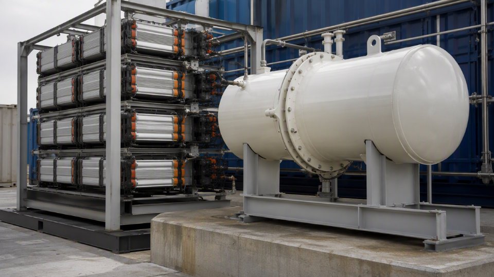
FAT completion is not just a technical milestone — it is the contractual event that closes the manufacturing battery limit and opens the logistics phase. A signed FAT certificate (co-signed by the owner’s representative or an authorized TPI inspector) documents that the vessel passed hydrostatic testing, dimensional verification, nozzle orientation checks, and nameplate review. Without that signed document, the vendor should not release the package to logistics. With it, the scope responsibility for the physical condition of the vessel formally begins its transfer.
Any punch list items outstanding at FAT create a scope ambiguity that can complicate damage claims later. Best practice: categorize outstanding items as Category A (must clear before release) and Category B (can close after delivery with agreed compensation holdback). Document this split in the FAT minutes.
Oversized and Heavy Lift Cargo: Who Owns the Route Survey?
Pressure vessels exceeding roughly 3.8 m in outer diameter or 40 t in gross weight — both thresholds vary by country and specific road authority jurisdiction — require route surveys, over-dimensional transport permits, and typically escort vehicles. This is not a freight forwarder’s standard service; it involves civil engineering assessment of bridge load ratings, overhead clearance surveys, and sometimes temporary road modifications.
Define in the PO who arranges and pays for this work. Common practice under FCA terms is that this falls to the EPC logistics contractor from the vendor’s gate onward. Under DAP, it falls to the vendor’s nominated logistics partner. Either way, the party responsible needs the certified lifting plan and the vessel’s center-of-gravity documentation from the manufacturer — another item that belongs in the vendor document register, not improvised at dispatch.
Port Documentation and the Customs Battery Limit
The vendor’s document production responsibility typically covers: commercial invoice, packing list, certificate of origin, material mill certificates packaged with the shipment, and a dangerous goods declaration when the test medium or any residual process fluid triggers ADR or IMDG classification. The freight forwarder produces the bill of lading and handles the EUR.1 or Form A preferential tariff certificates in applicable trade corridors.
One common failure point: the certificate of origin gets issued with a manufacturing location that doesn’t match the actual fabrication facility because the vendor subcontracted a shell course. Customs authorities flag this. Resolve subcontracting traceability in the vendor qualification stage, not at the port.
Site Receiving Inspection as the Final Battery Limit Handover
The EPC site team’s receiving inspection — dimensional check against the certified drawing, visible damage survey, nozzle protection cap inventory, nameplate legibility — is the terminal event in the logistics battery limit. The vendor’s liability for visible transit damage ends when proof of delivery is signed without notation of damage. Any damage found after POD signature with no documented reservation becomes a freight insurance claim, not a vendor warranty claim.
Latent defects — internal weld discontinuities not detectable by visual inspection at receipt — remain the vendor’s liability per the warranty clause, typically 12–24 months from mechanical completion or first operation, whichever comes first. That clause boundary needs to be in the PO, because the logistics battery limit hands over the hardware but it does not extinguish the manufacturing warranty.
How to Write Battery Limit Clauses into a Pressure Vessel Purchase Order
A technically sound battery limit definition is worthless if it lives only in a project engineering memo. It has to be contractually binding — embedded in the purchase order itself, with referenced attachments that carry the same legal weight as the PO body. Most scope disputes that reach formal arbitration trace back to one failure: the PO described intent, not boundary. Here is how to make the language enforceable.
Use a Battery Limit Matrix as a Mandatory PO Attachment
The Battery Limit Matrix (BLM) is a structured table — not a paragraph, not a bullet list — that assigns every interface item to a named scope owner. Attach it as Exhibit A (or equivalent) and state in the PO body that in any conflict between the BLM and general conditions, the BLM governs for scope questions.
A representative partial BLM for a skid-mounted separator package looks like this:
| Interface Item | In Vendor Scope | In EPC Scope | Interface Responsibility |
|---|---|---|---|
| Vessel body, heads, nozzles | ✓ | — | Vendor |
| First flange face (each nozzle) | ✓ (supply) | ✓ (connect) | Vendor supplies blind flange; EPC makes field joint |
| Saddle supports, skid base frame | ✓ | — | Vendor |
| Anchor bolts and grout | — | ✓ | EPC civil |
| Local pressure gauge (flanged, per datasheet) | ✓ | — | Vendor |
| Junction box wiring beyond skid edge | — | ✓ | EPC I&E |
| Shop primer coat (per paint spec Rev. B) | ✓ | — | Vendor |
| Field finish coat and insulation | — | ✓ | EPC |
| Hydrostatic test certificate | ✓ | — | Vendor |
| Third-party witness at FAT | — | ✓ | EPC arranges, Vendor facilitates |
Every nozzle gets its own row. Every instrument listed on the vessel datasheet gets its own row. Gaps in the matrix become disputed costs later.
Lock the P&ID Revision in the PO Body
Write it explicitly: “Vendor scope ends at the first flange face on each process tie-in as shown on P&ID drawing [number], Revision C, dated [date].” That revision lock is non-negotiable. EPC projects routinely issue P&ID revisions through detailed design — Revision D, E, F — and without a locked reference, each revision becomes a potential scope expansion argument. If a later revision changes a nozzle size or adds an instrument connection, that triggers a formal engineering change notice, not a verbal instruction to the shop.
Write an Explicit Exclusions List in the PO Body
Inclusion language alone is not enough. Courts and arbitration panels consistently give significant weight to explicit exclusion language when awarding disputed costs. List these in plain text in the PO body: anchor bolts and foundation hardware, field insulation and cladding, field painting beyond shop primer, interconnecting piping beyond the first flange face, MCC wiring and cable trays, civil foundation design and construction, and any commissioning labor unless separately priced. Each line removes an ambiguity that would otherwise cost 2–6 weeks of claim correspondence.
Define the Change Order Trigger and Response Window
State it in the PO: any work request that extends scope beyond the agreed BLM requires a written Engineering Change Notice (ECN) with documented price and schedule impact before any work begins. Specify the vendor’s response commitment — 5 to 7 business days is typical for fabricated vessel packages, depending on the complexity of the change. Without this clause, vendors face pressure to absorb scope additions to protect the relationship, and the cost surfaces later as a lump-sum dispute at project closeout.
Verbal or email-only scope extensions on pressure vessel POs are routinely rejected in ICC arbitration when the original PO required written ECNs for scope changes.True
ICC arbitration precedent consistently holds that contractual change order procedures must be followed; informal scope additions without written authorization generally do not override explicit PO change control clauses.
Link Battery Limits to the Warranty Clause
The warranty section should state specifically that the vendor warrants vessel performance and mechanical integrity up to and including the battery limit flange faces, as defined in the BLM. Performance degradation or damage caused by conditions originating outside those boundaries — including field piping loads, incorrect foundation stiffness, or improper insulation trapping moisture against the shell — falls outside the vendor’s warranty obligation. Without this linkage, warranty claims after commissioning become expensive technical arguments about root cause.
PO Review Checklist Before Signature
Before the PO is executed, a procurement engineer should confirm: the BLM is signed by both parties and attached as a numbered exhibit; every referenced drawing carries a locked revision number and date; the VDR schedule listing all required deliverable documents is attached with agreed submission dates; Incoterms 2020 are specified with a named place (e.g., CIF Port of [destination], named port); the FAT completion certificate template is agreed and referenced; and the ECN procedure including response time is explicitly stated. A fifteen-minute pre-signature checklist against these six items eliminates the majority of scope disputes that otherwise take months to resolve.
Frequently Asked Questions About Battery Limits in Pressure Vessel EPC Packages

What is the standard battery limit for a vertical separator package supplied to an EPC project?
The generally accepted boundary covers the first flange face on every process nozzle, instrument nozzle, and drain or vent connection; the underside of the saddle base plate or skid frame baseplate; shop-applied primer coat to the specified DFT; the hydrostatic test certificate; and the ASME U-1 data report or CE Declaration of Conformity, depending on the applicable code. The agreed VDR document package is included at that same handover point.
Everything beyond those lines is EPC scope by default: field piping beyond the first flange, anchor bolts and foundation civil work, field-installed instruments, grounding conductors beyond the local junction box, and secondary steel such as access platforms unless explicitly added to the vendor scope in the datasheet. These exclusions are not obvious to a procurement team buying its first custom separator package — spelling them out in a Battery Limit Matrix attached to the PO prevents the ambiguity from turning into a change order three months into fabrication.
Who is responsible for safety relief valve outlet piping?
Standard practice assigns the SRV itself to vendor scope: installed, set to the specified set pressure, and supplied with a manufacturer’s test certificate. The discharge piping from the SRV outlet flange to the flare header is EPC scope. That boundary must be written explicitly in both the P&ID tie-in note and the PO — not left to convention. ASME Section VIII and API 520/521 govern SRV sizing and installation requirements, but neither document assigns commercial responsibility for downstream discharge piping. Local pressure safety regulations in some jurisdictions require the discharge system to be engineered as part of the vessel package; verify this with the authority having jurisdiction before PO award, not during HAZOP.
ASME Section VIII Division 1 requires the vessel manufacturer to install and test the SRV before the U-1 data report is signed, but the standard does not specify who owns the downstream discharge piping commercially.True
ASME Section VIII Division 1, UG-125 through UG-136, covers pressure relief device requirements for the vessel itself. Commercial responsibility for discharge piping is a project contractual matter, not a code requirement.
How does the Incoterms selection affect the vessel vendor’s battery limit?
It doesn’t change the engineering battery limit — the first flange face stays the first flange face regardless of trade terms. What Incoterms 2020 determines is the logistics battery limit: who owns risk and cost at each stage of transport. Under FCA, the vendor’s exposure ends when the nominated carrier takes physical custody at the vendor’s facility after FAT. Under CPT or CIF, the vendor arranges and pays for main carriage but risk transfers at origin. Under DAP, the vendor is responsible until the equipment arrives at the named destination, typically the project site gate — which adds significant insurance and freight management complexity for oversize pressure vessels. Mixing up these boundaries on a heavy-wall reactor or a tall column is how projects absorb $30,000–$120,000 in unbudgeted freight and insurance costs, depending on route distance, vessel weight class, and port congestion.
What documents must a vendor deliver at the battery limit handover?
At minimum: as-built GA drawing with revision status, nozzle schedule, material test reports for pressure parts, weld map with NDE reports and film or digital records, hydrostatic test report, ITP with all hold and witness points signed by the relevant parties, ASME U-1 data report or PED Declaration of Conformity, coating inspection records including DFT readings, FAT completion certificate, and the final spare parts list. The complete mandatory list lives in the VDR attached to the PO. Any document absent at handover delays mechanical completion sign-off — on a critical-path vessel, a missing U-1 report can hold up the entire unit commissioning sequence.
Can the EPC contractor extend the vendor’s battery limit after PO award?
Yes, but only through a formal engineering change notice or change order with written cost and schedule impact from the vendor. Verbal instructions and email-only directives to extend scope — “just add the nozzle reinforcement pads for the customer’s platform clips” — are a real commercial risk that fabrication shops see regularly. The Battery Limit Matrix signed at PO award is the binding reference document. Any deviation from it that is not covered by a signed change order leaves both parties exposed: the vendor may absorb cost silently to protect the relationship, or the EPC contractor may face a dispute at final invoice.
What is the difference between a battery limit and a tie-in point?
A tie-in point is a physical location on the plant piping system where the new vessel package connects to existing or EPC-installed lines — a specific flange, a branch connection on a header, a weld bevel on a hot-tap. The battery limit is the contractual scope boundary. The two often coincide: the battery limit for a separator package is frequently the tie-in flange face on the inlet nozzle. But they can diverge. On a skid-mounted package, the battery limit might be defined at the skid edge with a short spool piece between the vessel nozzle and the skid edge flange — the tie-in point is then at the skid edge, but a length of piping inside the skid is vendor scope. Getting that distinction wrong on a drawing means either the vendor ships an incomplete skid or the EPC site crew fabricates piping the vendor already supplied, paying twice for the same steel.