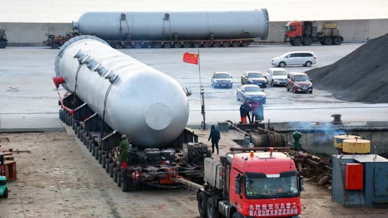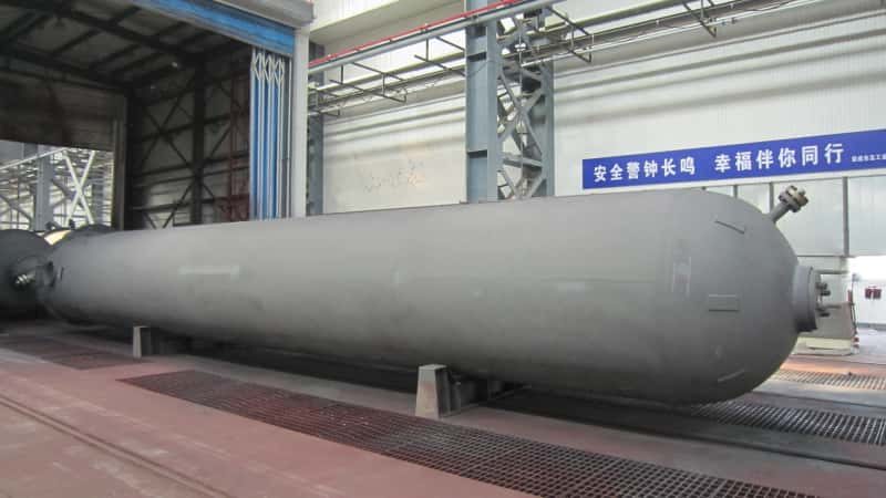

A vessel supplier’s quotation may include a shipping weight while the civil team needs to start its foundation assessment. The missing information is not just another weight total: it is the equipment configuration, load case and support interface behind the numbers.
Request installed empty, operating and applicable test weights with their component and liquid-inventory basis, the corresponding centers of gravity, and the forces and moments transferred to the supporting structure for the required load cases. Include support locations, coordinates, units, combination assumptions and document status. Reconcile shipping data with the installed configuration, and have the assigned equipment and civil designers confirm the inputs for the intended design activity.
For large custom vessels and process towers, this handover connects equipment procurement with civil design. The checklists below help define that interface; the actual project requirements determine the cases, analysis and approvals. They do not provide foundation sizes, allowable soil pressures or universal load combinations.
Separate Shipping, Installed Empty, Operating and Test Conditions
Request a defined equipment configuration for each weight case. A shipping figure describes what is being transported; it does not establish what will be installed, filled or supported by the permanent foundation.
Use the following comparison to agree the required submissions. These are discussion categories, not a mandatory test or construction sequence.
| Condition | Information to establish | Consequence for the civil handover |
|---|---|---|
| Shipping | Items included in the shipment, temporary transport items, equipment orientation and transport supports | Reconcile with the installed configuration before using any figure in a foundation assessment |
| Installed empty | Equipment and attachments present on the permanent supports, with the defined empty condition | Provides a distinct equipment state; identify items still to be installed or removed |
| Operating | The relevant process inventories, densities, liquid levels and installed equipment | Provide the operating states that matter to the project, rather than one unexplained total |
| Hydrotest, where applicable | Factory or site location, test inventory, orientation, installed items and support arrangement | Identify which supports receive the test load; a factory test does not automatically load the site foundation |
Codeware’s example report separates empty, operating and test totals in its weight summary, then identifies the vessel condition in a separate foundation-load summary. That separation is useful for procurement; the example’s numbers are not inputs for another vessel. Codeware example report, printed pages 13 and 18.
For a proposed field hydrotest, ask whether it will occur on the permanent foundation and what equipment will be fitted at that time. If no field test is planned, do not silently describe the shop test as a site case. Have the project team confirm the applicable testing and construction conditions.
Shipping weight is not necessarily smaller than installed empty weight: temporary transport items may be included, while equipment to be fitted at site may be excluded. Request the scope behind each figure instead of assuming an ordering.
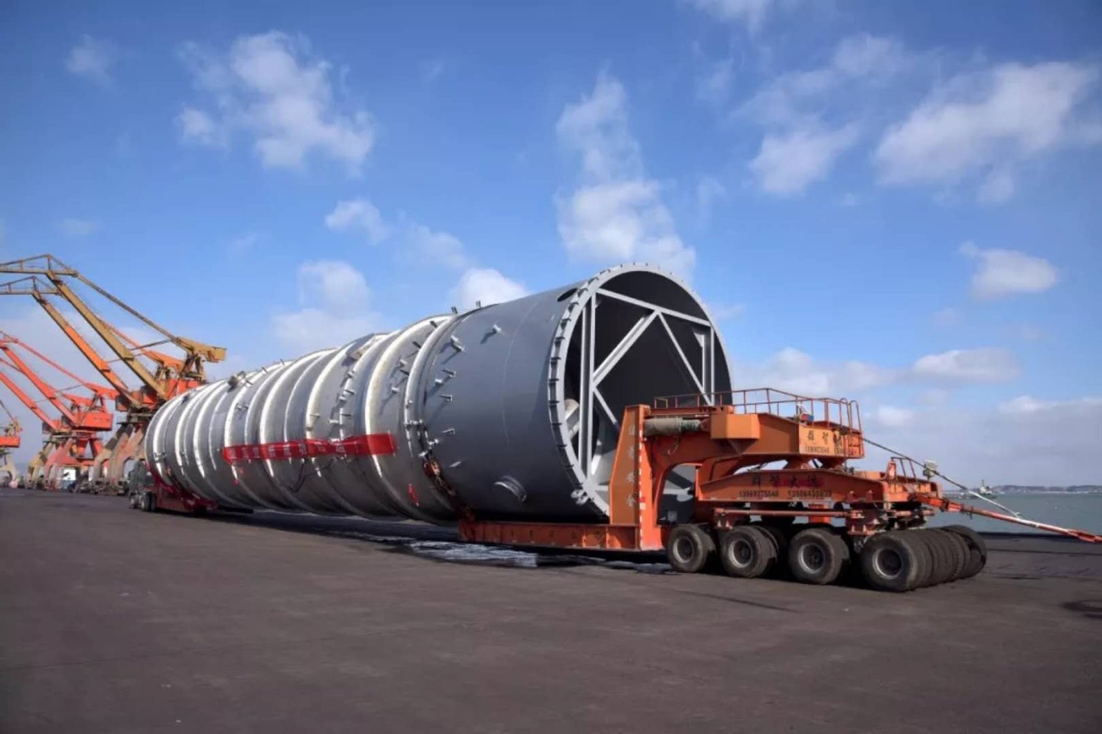
The separate guide to large pressure vessel export shipping addresses the transport stage. Here, the required deliverable is the equipment loading at the agreed civil interface.
Make the Weight Breakdown and Center of Gravity Traceable
Ask for a weight breakdown that can be reconciled with the current arrangement drawing and each equipment condition. A total without inclusion notes leaves the receiving engineer unable to tell whether an item is missing or already counted.
Check these groups against the actual scope:
- Vessel construction: The pressure-containing body, supports, linings and permanent internals included in the model.
- Installed additions: Insulation, platforms, ladders and attached equipment, with a clear allocation for anything supplied or installed by others.
- Contents: The process or test inventory for that case, including the relevant density, temperature basis and liquid level. For multiple compartments, identify the inventory in each.
- Temporary items: Test closures, temporary attachments or transport items that remain present in a particular state, with their inclusion or exclusion recorded.
Codeware’s example weight summary distinguishes vessel elements, attachments and operating/test liquid contributions. Its blank or zero entries describe that example only; they do not justify omitting a corresponding item from another project.
For each submitted center of gravity, identify the equipment condition, coordinate axes and datum on the referenced drawing. A shipping center of gravity belongs to the shipping configuration. It should not be relabelled as the operating value without checking the changed inventory and installed items.
Where an analysis distinguishes new and corroded equipment conditions, retain those labels in the weight and reaction schedules. They are model conditions to be reconciled, not interchangeable totals.
Illustrative situation: A tower receives an additional platform on one side after a preliminary weight estimate. Even if the increase in total mass is small, its location still needs to be reflected in the equipment model and reviewed for its effect on the civil interface. This is a coordination example, not a claim that a particular foundation would fail or require enlargement.
Keep mass and force separate. A field expressed in kg reports mass; N and kN report force, while a moment may be expressed in kN·m. NIST explicitly distinguishes mass from weight as a force. Keep the familiar procurement labels “empty weight” and “operating weight” if useful, but state what the numbers and units mean. Do not copy a mass value into a force column without the appropriate conversion and documented basis. NIST SI checklist, item 19.
Request Foundation Reactions for the Applicable Load Cases
Request the forces and moments transferred at the agreed equipment-to-civil interface for each applicable case. Total equipment mass alone does not describe horizontal loading, overturning effects or how loads are distributed among supports.
Define the reporting location first. For example, a skirt-supported vessel may have a resultant reported at its support base, while equipment with several supports needs information that identifies the loading at the relevant interfaces. The responsible designers should agree the support model and the level of detail required by civil engineering. An overall resultant is not automatically a complete distribution to individual supports.
Also state whether the reported values are loads exerted by the equipment on the supporting structure or reactions acting in the opposite direction. Include the axis directions and positive moment convention. A change in reporting elevation or location may require a corresponding moment transformation, not merely a new table heading.
Codeware describes its foundation-load summary as a means of transferring condition-specific load information and support details to civil and structural engineers. The example report’s foundation page explicitly labels its results as service loads for Allowable Stress Design, but its displayed rows cover weight-only loading. It is not a template demonstrating every required project case. Read both the load scope and the result qualifications before using supplied values.
The project loading basis determines which environmental and other actions must be assessed alongside the equipment states. For example, ASCE’s public introduction to ASCE/SEI 7-22 identifies wind, seismic and other loading categories, together with load combinations. This establishes the scope of that referenced standard; it does not establish its applicability to every project or supply the combinations for this vessel. Confirm the governing jurisdiction, adopted edition and project requirements. ASCE 7-22 overview.
Common misconception: “Hydrotest weight is the largest number, so it governs the foundation.” A large test inventory may be important for vertical loading, but that does not identify the controlling case for every check. A lighter state with an applicable lateral-load combination may be more demanding for uplift or overturning. The civil designer must compare the relevant cases and criteria; neither “test” nor “operating” is a universal governing label.
Where connected piping contributes to the equipment loading, identify the applicable input revision and confirm whether its effects are already included in the exported foundation loads. This avoids omission or double counting. The separate pressure vessel nozzle-load specification guide covers that upstream interface; nozzle-load acceptance alone does not establish the final foundation reactions.
Use One Coordinated Civil Handover Schedule
Link each reported load set to its equipment state, support interface and source revision. Civil engineering should be able to trace a row of results back to the drawing and assumptions that produced it.
The following is an illustrative handover checklist, not a completed calculation sheet or a substitute for the project’s document requirements.
| Field | Information to request | Review question |
|---|---|---|
| Equipment identity | Vessel tag and referenced arrangement/model revision | Does this submission describe the equipment being purchased? |
| Case identity | Case ID, physical state and combination definition | Is this a single state, a combined design case or an envelope? |
| Weight basis | Total and component scope, inventory density/level and exclusions | Can the total be reconciled without omissions or duplication? |
| Center of gravity | Coordinates, units, datum and applicable equipment condition | Is the location tied to the same configuration as the weight? |
| Support interface | Support IDs, locations, reporting elevation and model assumptions | Are results supplied for the locations required by civil engineering? |
| Forces and moments | Applicable signed components and explicit force/moment units | Are the directions and the side of the interface defined? |
| Loading scope | Included actions and referenced external-load inputs | Which effects remain for another discipline to add? |
| Combination basis | Governing specification/edition, factors already applied and intended design use | Can the receiving engineer use the results without applying factors twice? |
| Result interpretation | Simultaneous sets or clearly labelled envelopes, with source case references | Do the components belong together, and can extremes be traced? |
| Document status | Originator, checker/approver, issue date, revision and unresolved items | Is the information authorized for the proposed civil activity? |
The need to connect load results with equipment conditions and support information is illustrated by Codeware’s foundation-summary description. The additional review questions above are a procurement coordination aid, not quoted standard clauses.
Keep any envelope distinct from a simultaneous result. The maximum downward force, horizontal force and overturning moment may come from different cases. A civil designer may request an envelope for a defined assessment, but its construction and intended use should be explicit; it should not be presented as an observed operating state.
Finally, agree the boundary of the delivered loads. For example, if the supplier reports loads at the vessel base, clarify which foundation or supporting-structure self-weights remain in the civil model. The table should make that boundary visible rather than relying on the reader to infer it from the total.
Control Preliminary Inputs, Approval and Later Changes
Distinguish data issued for early planning from data accepted for a specified design or construction activity. A supplier estimate can help an EPC team start coordination, but its presence in a quotation does not make it an approved foundation input.
Agree who supplies the process inventories and site criteria, who develops the equipment weight and reaction data, and who checks their use in the civil design. A practical allocation is for the equipment designer to issue the vessel data, the EPC to coordinate the interfaces, and the assigned civil designer to assess the supporting works. Confirm the actual contractual and engineering responsibilities, including work assigned to other parties.
Use the following document-control sequence as a starting point:
- Issue the available basis. Send the preliminary arrangement, process conditions, installation location, applicable test plan and requested civil deliverables with the enquiry. List missing inputs and the party expected to resolve each one.
- Record the permitted interim use. Identify the assumptions behind estimated weights and reactions. Have the authorized project reviewers decide which planning or design activities they can support and which remain dependent on further information.
- Reconcile the coordinated submission. Check that the arrangement, weight breakdown, center of gravity, support interfaces and case-based reactions use compatible revisions. Close relevant comments and record acceptance for the intended activity.
- Notify and assess changes. When the basis changes, identify the affected equipment and civil documents, issue revised data where needed, and obtain the responsible reviewers’ disposition before relying on superseded inputs.
Changes worth routing for review include revised plate thickness, added internals or platforms, different liquid density or level, changed support geometry, and revised piping or environmental-load inputs. The required response depends on the effect of the change, not simply on whether the total weight increased.
Do not introduce an arbitrary percentage below which changes are ignored. If the project uses an agreed allowance or change threshold, record its basis, limits and responsible approver. Retain unresolved items visibly until their disposition is documented.
Frequently Asked Questions
Should a blank load component be treated as zero?
No. A blank may mean that the value is unknown, excluded or not reported. Ask the originator to distinguish a confirmed zero from “not applicable” and “pending,” and to explain those status labels. Civil engineering should not have to infer an engineering result from an empty cell.
Is a total package weight enough when equipment shares a supporting frame?
Not by itself. Establish whether the handover concerns the vessel-to-frame interface or the frame-to-foundation interface. The total package weight does not identify its distribution to the frame’s foundation connections. Agree who calculates and issues the reactions at the boundary required for the civil design.
If the total weight is unchanged, can an existing civil submission remain valid?
Only after the responsible reviewers confirm that the relevant basis remains valid. Changed equipment positions, support locations, center of gravity or applied loads can alter the interface results without changing the total mass. Ask for a documented assessment of the change rather than assuming the old submission still applies.
Include Civil Interface Data in the Vessel Enquiry
For custom industrial pressure vessels, submit the equipment datasheet, available arrangement drawing, process inventory conditions, installation location and project loading requirements together. Identify the applicable test arrangements and request a coordinated weight, center-of-gravity and foundation-reaction package with clear issue status.
When you share the project requirements with WSHI, ask which equipment calculations and civil-interface documents are included in the proposed supply scope, and which remain with the EPC or other designers. This gives the complete vessel enquiry a defined engineering handover, while leaving foundation acceptance with the assigned project team.
References
Sources reviewed on October 15, 2026. The Codeware report is an example, and the ASCE source is a public overview rather than the standard’s full text. No example design values or load-combination factors have been adopted for this article.
- Codeware. COMPRESS Pressure Vessel Design Calculations — Steam&ControlSystems example. Undated report; settings identify COMPRESS 2024 Build 8400 and ASME Section VIII Division 1, 2023 Edition. Weight Summary, printed page 13, and Foundation Load Summary, printed page 18 (PDF pages 16 and 21).
- Codeware. Pressure Vessel Foundation Loads Summary. Public feature description; page timestamp December 3, 2025. Used for the transfer of condition-specific loads and support information to civil and structural engineering.
- National Institute of Standards and Technology. SI Unit Rules and Style Conventions Checklist. Online February 1998; last update September 2004. Item 19, weight versus mass.
- American Society of Civil Engineers. ASCE/SEI 7-22 — Minimum Design Loads and Associated Criteria for Buildings and Other Structures. Official overview of the 7-22 edition; used only for its stated loading and load-combination scope. Project adoption and detailed requirements must be established separately.