
During a shell-and-tube heat exchanger procurement review, the thermal rating may already demonstrate the required heat duty and acceptable pressure drop. Yet those results do not tell the buyer whether the proposed tube bundle has been adequately evaluated for flow-induced vibration.
Buyers should review the operating cases covered, the fluid properties and phase conditions used, the exchanger geometry assessed, the applicable vibration-analysis method, the supporting results, and the unresolved limitations. They should also confirm who is responsible for reviewing the findings and reassessing them when process conditions or equipment design change.
The objective is not to obtain a universal safe velocity or demand an identical calculation package for every exchanger. It is to establish whether the submitted evidence supports the proposed equipment within its agreed operating and contractual boundaries.
Why Is Thermal Compliance Not Enough to Clear Vibration Risk?
A shell-and-tube heat exchanger can meet its specified heat duty and pressure-drop limits without demonstrating that its tubes are acceptably protected against flow-induced vibration. Thermal performance and vibration behavior depend on overlapping operating and geometric conditions, but they answer different engineering questions.
A thermal rating establishes whether the proposed exchanger can transfer the required heat under specified process conditions while remaining within hydraulic constraints. A vibration assessment considers how fluid forces interact with tubes and their supports, whether the resulting response is acceptable, and whether relevant damage mechanisms have been addressed.
HTRI’s research on avoiding flow-induced vibration identifies vibration as a design constraint alongside heat transfer and pressure drop. It also emphasizes that the interaction between flow and exchanger geometry matters; vibration problems should not be inferred from flow rate alone. (1)
For example, two exchanger proposals may satisfy the same process duty while using different tube layouts, shell configurations, support arrangements, or inlet designs. Those differences can change local flow conditions and the dynamic behavior of the tube bundle. A satisfactory thermal comparison therefore does not establish that the vibration assessments for the two proposals are equivalent.
Potential consequences of excessive vibration include tube fatigue and fretting wear. These damage mechanisms are discussed in established vibration research and should be distinguished from the broader equipment symptoms covered in our heat exchanger failure guide. (3, 4)
For procurement purposes, the immediate question is not whether the supplier can state that the design is vibration-free. It is whether the supplier can identify the evaluated operating conditions, the actual exchanger configuration, the assessment method, and the evidence supporting its conclusion.
Which Operating Conditions Must the Vibration Review Cover?
A useful vibration review must cover the operating cases that can actually occur within the exchanger’s agreed service envelope. Checking only the nominal design point may leave relevant flow distributions, fluid properties, or phase conditions outside the assessment.
The process engineer and supplier should first establish the applicable operating cases. Normal, maximum, and minimum operation are useful starting categories, but the required cases depend on the particular process and equipment. Startup, shutdown, turndown, control transitions, or other off-design conditions should be included when they create relevant service conditions and fall within the agreed review scope.
| Operating case | Information the buyer should verify | Main review question |
|---|---|---|
| Normal operation | Concurrent flow rates, pressure, temperature, composition, and phase on both sides | Does the assessment cover the reference operating condition? |
| Maximum relevant operation | Actual permissible flow and associated fluid properties and inlet conditions | Have the potentially governing flow conditions been evaluated? |
| Minimum or turndown operation | Actual lower-flow state, including any associated property or phase changes | Could a different flow distribution or operating regime require separate consideration? |
| Applicable transient or abnormal operation | Defined event, concurrent process conditions, expected duration, and review applicability | Is this case relevant to vibration assessment, and is it within the agreed design or review basis? |
Editorial review template — not a project-specific operating matrix or manufacturer calculation report.
These cases should represent consistent process states. A maximum flow rate, minimum density, and extreme temperature must not be combined merely because each appears somewhere in the process datasheet. Such a combination is meaningful only if it represents a physically possible and contractually relevant operating condition.
Fluid Properties and Phase Conditions
For each applicable case, the review should identify the fluid conditions used in the analysis, rather than relying on a single nominal flow value.
Relevant information can include:
- Flow rate and the basis used to express it, such as mass flow or volumetric flow under stated conditions.
- Pressure, temperature, composition, density, and viscosity where relevant.
- Single-phase liquid, single-phase gas, or applicable two-phase operating states.
- Vapor fraction, phase distribution assumptions, or other two-phase information required by the selected method.
- Shell-side and tube-side operating conditions, with their relationship to the assessed configuration.
Phase information deserves particular attention. HTRI’s review of two-phase flow-induced vibration identifies uncertainties involving two-phase flow fields, added mass, damping, fluid excitation, and structural response. Accordingly, a method or result developed for a particular single-phase condition should not automatically be treated as valid for a changed two-phase service. (4)
Inlet Boundaries and Process Interfaces
The relevant inlet conditions should also be documented. A total shell-side flow rate does not, by itself, describe the local flow field around the tube bundle.
Buyers should establish the inlet nozzle arrangement, relevant flow entry conditions, and any upstream or internal features that materially affect the evaluated flow distribution. Where inlet maldistribution or an unusual connection arrangement is a concern, the responsible engineer should identify what boundary assumptions are used and whether additional information is required.
This is particularly important when comparing equipment from different suppliers. Two proposals can use the same nominal process datasheet while adopting different inlet arrangements or internal geometries.
The buyer’s acceptance criterion at this stage is traceable operating-case coverage, not an assumed universal safe flow velocity. Each relevant case should be listed, linked to a consistent process basis, and either evaluated or explicitly excluded with an agreed technical reason.
Which Equipment Details and Flow Regions Must Match the Assessment?
The vibration assessment must correspond to the exchanger configuration being offered for purchase. An analysis based on different tube geometry, support conditions, or inlet arrangements may not adequately represent the proposed equipment, even when both designs meet the same thermal duty.
The buyer should compare the assessment inputs against the latest applicable thermal datasheet, mechanical drawings, and equipment configuration.
Geometry and Tube Support Information
Relevant design information may include:
- Tube outside diameter, wall thickness, length, material, and layout.
- Tube pitch and bundle arrangement.
- Effective unsupported tube spans and the locations of intermediate supports.
- Baffle or support-plate arrangement, including relevant spacing, cuts, and support conditions.
- Tube-to-tubesheet support conditions and, where applicable, U-bend geometry.
- Shell configuration, inlet and outlet nozzle locations, and flow distribution features.
Not every dimension needs to appear in the main assessment summary. However, the report or its controlled supporting documents should allow reviewers to identify the configuration actually evaluated.
Tube support deserves attention because the dynamic response depends on structural conditions as well as fluid excitation. A change to baffle spacing or support arrangement should therefore be assessed for its possible effect on vibration behavior rather than treated automatically as a minor fabrication detail.
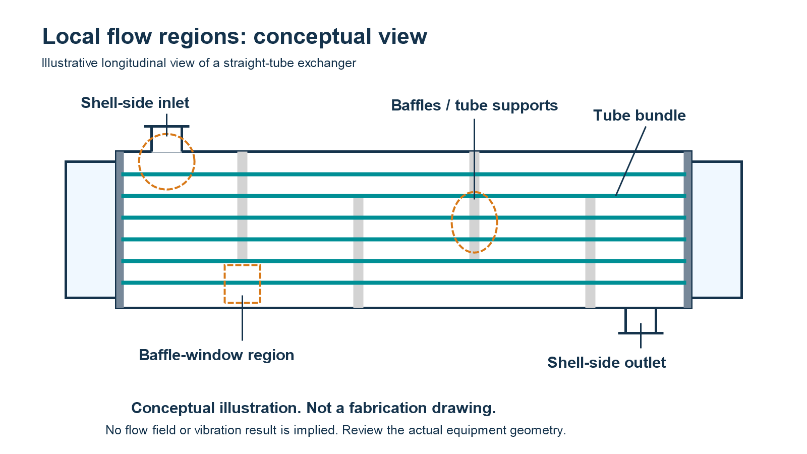
Local Flow Regions That May Require Attention
An overall shell-side flow figure cannot represent every local flow condition.
Relevant areas may include the inlet region, tube bundle windows, bypass or flow lanes, and unsupported U-bend regions where present. The importance of each region depends on the exchanger’s actual geometry and flow arrangement.
HTRI’s STV-2 research involved shell-side water-flow testing with configurable tube bundles and nozzles. Its later STV-16 study examined the influence of inlet nozzle arrangements on fluidelastic-instability screening for particular U-tube configurations. These studies support the need to recognize configuration-specific effects, not the assumption that every exchanger has the same critical location. (5, 6)
Confirm the Design Revision
A review statement should identify the relevant exchanger tag, equipment configuration, document revisions, and date of the evaluated design.
If a supplier revises the tube layout, support spacing, shell arrangement, or another feature affecting the analysis, the buyer should request a documented assessment of whether the existing vibration review remains applicable.
The purpose is to establish traceability between the engineering evidence and the equipment that will actually be manufactured.
What Evidence Should the Supplier’s Vibration Assessment Provide?
A supplier’s vibration assessment should provide a traceable technical basis for its conclusion, not merely a statement that vibration has been checked.
The required level of detail depends on the project specification, exchanger service, analysis method, and allocated engineering responsibilities. A preliminary screening may be sufficient for some agreed review scopes, while other applications may require more detailed evaluation. The buyer should be able to distinguish these situations from the submitted evidence.
The Main Evidence to Review
An engineering overview by Pettigrew and Taylor describes vibration analysis in terms of flow distribution, dynamic properties, excitation mechanisms, predicted response, and damage assessment. For procurement purposes, these technical activities can be translated into reviewable evidence rather than reproduced as a calculation procedure. (2, 3)
| Evidence category | What the buyer should look for | Why it matters |
|---|---|---|
| Equipment identification | Exchanger tag, configuration, drawing references, and revision status | Establishes which equipment design was assessed |
| Operating-case coverage | Applicable process cases, fluid properties, phase assumptions, and exclusions | Shows whether the review covers the agreed operating envelope |
| Geometry and structural basis | Tube configuration, relevant unsupported spans, support conditions, and critical regions | Connects the analysis to the proposed mechanical design |
| Assessment method | Named method or procedure, its applicability, and stated assumptions | Allows the reviewer to judge whether the chosen approach fits the service |
| Technical results | Relevant screening findings, calculated responses or indicators where applicable, and comparison with the selected criteria | Provides evidence behind the conclusion |
| Limitations and uncertainties | Conditions outside the method’s scope, unresolved inputs, and qualifications | Prevents a limited result from being interpreted as universal acceptance |
| Conclusions and actions | Status for evaluated cases, outstanding issues, corrective actions, and required reassessment | Supports a traceable procurement decision |
Editorial document-review template. This table is not reproduced from TEMA, API, HTRI, or a manufacturer’s calculation report.
Method Applicability Matters More Than Software Names
The supplier should identify whether the submitted work is a preliminary screening, a detailed vibration calculation, or an engineering evaluation incorporating additional analysis.
A report should explain why its method is applicable to the actual service, including relevant flow regimes, excitation mechanisms, structural behavior, and limitations.
For example, a calculation addressing a specified shell-side crossflow mechanism should not automatically be interpreted as having evaluated every possible flow-induced vibration mechanism. Similarly, the use of computational fluid dynamics does not by itself establish that the tube’s dynamic response and the relevant acceptance criteria have been evaluated.
HTRI’s STV-16 study illustrates the use of CFD alongside structural-response considerations for a defined U-tube vibration problem. Its 2026 STV-17 abstract also discusses uncertainties in predicting vibration under parallel-flow excitation. These are examples of why method scope and supporting assumptions should be visible to reviewers. They do not establish a universal requirement to use CFD or a universal accuracy level for all exchanger vibration assessments. (6, 8)
Review the Conclusion, Not Just the Calculation Output
A technically useful conclusion should explain:
- Which operating cases and equipment configuration were evaluated.
- Which mechanisms and regions were covered by the selected approach.
- What assessment criteria were applied and where those criteria came from.
- Whether the evaluated cases met those criteria.
- Which assumptions, exclusions, or unresolved issues affect the conclusion.
If the supplier reports a satisfactory result, the buyer should be able to connect that conclusion to the applicable inputs and criteria. A numerical indicator without its interpretation or an unconditional statement without supporting scope information is insufficient for a meaningful technical review.
The applicable standards and contractual requirements also need to be identified. TEMA’s official website describes its 2026 Standards edition and an updated heat exchanger specification sheet. API’s official catalog lists API 660, Shell-and-Tube Heat Exchangers, as a tenth-edition standard. The project must still establish which documents and editions govern the purchase. Their publicly accessible listings do not, by themselves, establish that a particular vibration assessment satisfies every contractual requirement. (7, 9)
For related thermal and hydraulic commitments, see our shell-and-tube heat exchanger performance guarantee guide. Those commitments should remain distinguishable from the vibration review’s scope and conclusion.
How Should Buyers Close Review Comments and Manage Design Changes?
A vibration review should be closed through documented engineering decisions. Even a technically detailed report has limited procurement value if its process inputs are unapproved, its applicable design revision is unclear, or important qualifications remain unresolved.
The EPC contractor or buyer should establish how the process engineer, equipment supplier, mechanical reviewer, and any appointed independent reviewer exchange information and resolve comments.
Assign Responsibilities Before Approval
The following allocation is an illustrative starting point, not a mandatory responsibility matrix. Final ownership should follow the purchase order, engineering contract, and project document-control procedure.
| Participant | Typical information or decision responsibility |
|---|---|
| Process engineer or process licensor | Establish and confirm operating cases, process properties, phase conditions, and relevant process uncertainties |
| Equipment supplier and responsible design team | Identify the evaluated equipment configuration, perform or obtain the agreed assessment, document its basis, and respond to technical comments |
| EPC equipment engineer or purchaser’s technical representative | Check contractual coverage, coordinate review comments, and confirm that the submitted evidence corresponds to the proposed equipment |
| Independent technical reviewer, if appointed | Review the defined technical scope and identify findings or qualifications requiring resolution |
| Authorized project approver | Record acceptance, conditional disposition, or outstanding actions under the project’s approval procedure |
Where the purchaser provides the thermal design and another party fabricates the exchanger, those responsibilities need particular attention. A fabrication contract should not be assumed to include an independently performed vibration assessment unless the agreed scope says so.
Close the Outstanding Issues
Each material review comment should have a defined disposition, responsible party, and associated document revision.
For example, a supplier may state that the analysis covers single-phase operation while the approved operating envelope includes a relevant two-phase condition. The appropriate response is not to assume either automatic failure or automatic acceptance. The parties should determine whether that operating state requires additional evaluation, a documented technical justification for exclusion, or a revised contractual operating basis.
This is a hypothetical review situation, not a reported project case.
A practical review disposition can be recorded as:
- Accepted: Required evidence and technical responses are complete for the agreed scope.
- Conditionally acceptable: Specific remaining actions are expressly permitted by the project’s approval procedure and have assigned owners and deadlines.
- Open / hold: A material input, assessment finding, or required action remains unresolved and prevents the relevant approval.
These are suggested document-management labels, not formal vibration acceptance classifications.
Reassess the Effect of Design or Process Changes
A completed review should not be detached from subsequent changes.
If the approved design is revised, the responsible engineer should decide whether the change affects the vibration assessment basis. Relevant changes can include operating flow or phase conditions, fluid properties, tube dimensions, support arrangements, shell configuration, nozzle location, or another factor identified by the assessment method.
Not every change automatically requires a complete recalculation. However, a decision to retain the previous assessment should have a documented engineering justification.
Before releasing a shell-and-tube heat exchanger for procurement or fabrication, the buyer should therefore verify that the reviewed operating envelope, mechanical configuration, assessment conclusion, and design revision remain aligned.
Frequently Asked Questions
Can a preliminary vibration screening be sufficient?
Yes, where the screening method is applicable to the equipment and operating conditions, and the agreed project requirements permit that level of assessment. The screening should identify the evaluated cases, method, limitations, and conclusion. If its scope does not cover a relevant mechanism or condition, additional technical justification or analysis may be necessary.
Does CFD alone demonstrate that an exchanger is free from vibration problems?
No. CFD can be used to investigate flow fields, but a vibration assessment also needs to address the relevant fluid-structure interaction, dynamic response, and acceptance basis. Whether CFD is useful or necessary depends on the specific engineering problem and selected assessment method. HTRI’s STV-16 study provides an example of CFD used with structural-response considerations for a particular U-tube problem. (6)
Can a previous vibration assessment be reused for a revised exchanger design?
Only when the responsible engineer has established that the previous assessment remains applicable. The review should compare the operating cases, relevant geometry, support conditions, method assumptions, and assessed design revisions. A documented applicability review may support reuse; a change that materially affects the assessment basis may require additional evaluation.
Conclusion
Flow-induced vibration review is a question of traceable engineering evidence, not a single universal velocity limit. Buyers should connect the applicable process envelope to the exact exchanger configuration, review what the analysis actually covers, and close material qualifications before the relevant approval.
For an industrial exchanger procurement discussion, provide the equipment datasheet, applicable operating cases, process-fluid and phase information, preliminary arrangement, and project review requirements. These inputs help establish the thermal and mechanical documentation scope that needs to be agreed for the proposed equipment.
References
Chenoweth, J. M. (1989). STV-5: Design of Shell-and-Tube Heat Exchangers to Avoid Flow-Induced Vibration Problems. Heat Transfer Research, Inc. (HTRI). Public research abstract.
Pettigrew, M. J., & Taylor, C. E. (2003). Vibration Analysis of Shell-and-Tube Heat Exchangers: An Overview—Part 1: Flow, Damping, Fluidelastic Instability. Journal of Fluids and Structures, 18(5), 469–483. Article information and abstract.
Pettigrew, M. J., & Taylor, C. E. (2003). Vibration Analysis of Shell-and-Tube Heat Exchangers: An Overview—Part 2: Vibration Response, Fretting-Wear, Guidelines. Journal of Fluids and Structures, 18(5), 485–500. Article information and abstract.
Chan, A. M. C. (1999). STV-9: Review of Two-Phase Flow-Induced Vibration in Heat Exchangers. HTRI. Public research abstract.
Halle, H., Chenoweth, J. M., & Wambsganss, M. W. (1986). STV-2: Shellside Flow-Induced Tube Vibration in Typical Heat Exchanger Configurations. HTRI. Public research abstract.
Farrell, K. J. (2009). STV-16: Calculating Fluidelastic Instability of U-Tubes Near Inlet Nozzles. HTRI. Public research abstract.
Tubular Exchanger Manufacturers Association (TEMA). (2026). TEMA Standards—2026 Edition Information. Official standards page.
Farrell, K. J. (2026). STV-17: Parallel Flow-induced Tube Vibration in Shell-and-tube Heat Exchangers. HTRI. Public research abstract.
American Petroleum Institute (API). API Standard 660: Shell-and-Tube Heat Exchangers. Tenth edition listed in the official digital catalog, accessed October 20, 2026. API standards catalog.