
An industrial heat exchanger can miss its target outlet temperature, develop an unusual pressure drop, or show signs of fluid contamination without the underlying cause being immediately obvious. Fouling, changing process conditions, control problems, internal leakage, and mechanical deterioration can produce overlapping symptoms.
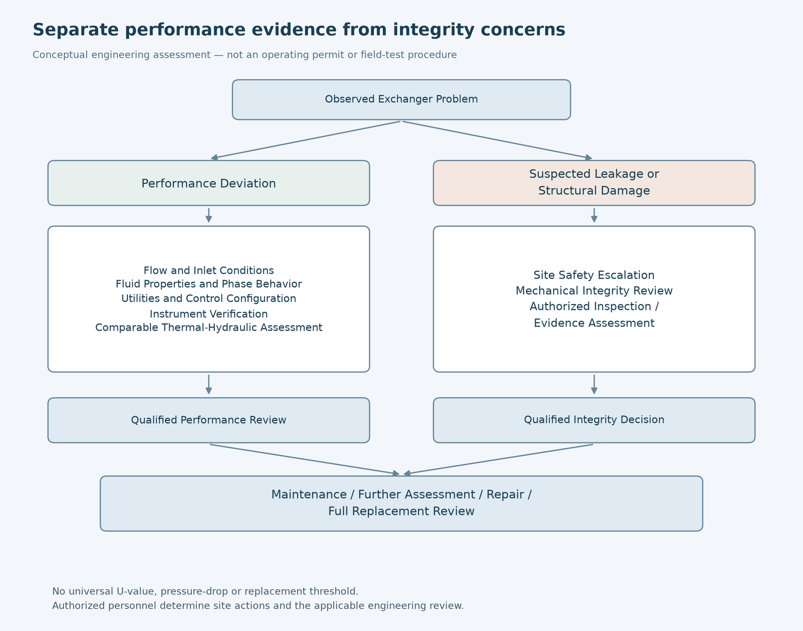
Before deciding whether an industrial heat exchanger needs cleaning, repair, or complete replacement, the owner should compare operating data under equivalent conditions, verify the reliability of the measurements, and review any evidence of leakage or mechanical damage. The final decision should be based on a qualified engineering assessment—not a single temperature reading, pressure-drop increase, or universal performance-loss percentage.
For chemical plants, refineries, and other industrial facilities, this distinction matters because a poorly performing exchanger is not necessarily structurally damaged, while an exchanger that continues to transfer heat may still have a serious pressure-boundary or cross-contamination problem.
This guide focuses on identifying credible failure evidence and preparing the technical information needed for a condition assessment or a complete shell-and-tube heat exchanger replacement enquiry. It does not provide operating instructions for suspected leaks, pressure testing, or field repairs.
What Are the Main Signs of Industrial Heat Exchanger Failure?
The first step is to separate the observed symptom from its possible causes.
Industrial exchanger problems can be grouped into four broad categories: thermal underperformance, abnormal hydraulic behavior, leakage or fluid contamination, and mechanical or structural deterioration.
Thermal Performance Decline
Common observations include:
- The process outlet temperature no longer meets its target.
- The exchanger transfers less heat under apparently similar conditions.
- Utility consumption or control-valve demand increases to maintain the same process target.
- The difference between measured and expected heat duty grows over time.
- A calculated overall heat transfer coefficient appears to decline.
These observations may be consistent with fouling, scaling, reduced effective heat-transfer area, or internal flow problems.
However, they can also result from changes in feed flow, fluid properties, inlet temperatures, utility conditions, phase behavior, bypass flow, or instrumentation.
A decline in apparent thermal performance is evidence of a problem to investigate—not proof of fouling on its own.
HTRI’s public discussion of troubleshooting heat exchangers identifies fouling, maldistribution, tube vibration, and other design or operating factors among the challenges that can affect exchanger performance.
Abnormal Pressure Drop or Flow Behavior
An unexpected change in differential pressure across the shell side or tube side may indicate:
- Deposits or partial blockage.
- A change in flowrate or fluid viscosity.
- Gas accumulation or unexpected phase behavior.
- Changes in the position of a valve or other system restriction.
- Internal mechanical or flow-distribution problems.
- Measurement or pressure-tap problems.
A higher pressure drop at a higher flowrate is not necessarily evidence of exchanger deterioration.
Similarly, a lower pressure drop does not always mean that the exchanger is cleaner. Reduced flow, bypassing, a changed flow path, or other system conditions may explain the result.
Pressure-drop trends should therefore be evaluated together with corresponding flow and fluid-property information.
Cross-Contamination or Leakage Indicators
An exchanger may develop internal leakage between its process sides or external leakage through pressure-boundary components and connections.
Possible observations include:
- Unexplained changes in fluid composition.
- Unexpected conductivity, pH, or contamination indicators where relevant to the service.
- Abnormal product-quality results.
- Process constituents appearing in a utility or another process stream.
- Visible external leakage, staining, or deposits around an accessible pressure boundary.
- Unexplained material-balance discrepancies.
The absence of a visible leak does not establish internal integrity.
The direction and consequence of an internal leak depend on the operating pressure difference and the connected systems. Leakage may transfer a hazardous or incompatible fluid to a location that was not designed to receive it.
The U.S. Occupational Safety and Health Administration (OSHA), in its refinery and petrochemical technical guidance, identifies cross-stream leakage and downstream hazards associated with failed heat-exchanger tubes.
Suspected containment loss or hazardous cross-contamination requires prompt escalation through the facility’s established safety and mechanical-integrity procedures. It should not be treated as a routine efficiency optimization question.
Mechanical and Structural Deterioration
Evidence requiring professional review may include:
- Wall thinning or localized corrosion.
- Cracking or suspected fatigue damage.
- Tube-to-tubesheet joint deterioration.
- Tube damage associated with vibration or flow.
- Gasket or flange leakage.
- Deformation or evidence of abnormal mechanical loading.
- Previously identified defects that may have progressed.
The location and significance of a defect matter as much as its visible appearance.
An exchanger may show acceptable thermal duty while a damaged component requires mechanical-integrity assessment.
Use a Symptom Matrix Instead of a One-Cause Diagnosis
| Observed symptom | Possible explanations | Evidence needed before drawing a conclusion |
|---|---|---|
| Lower heat duty or outlet-temperature deviation | Fouling, changed feed conditions, utility limitation, bypassing, or inaccurate data | Coincident flow and temperature records, process properties, validated thermal comparison |
| Increased differential pressure | Deposits, higher flow, viscosity change, partial blockage, or pressure measurement error | Flow-normalized comparison, fluid-property information, instrument review |
| Unexpected reduction in differential pressure | Reduced flow, a changed flow path, bypass, or other hydraulic changes | System configuration, actual flows, pressure instrument status |
| Product or utility contamination | Internal leakage, upstream contamination, sampling error, or another connected source | Confirmed analyses, material balance, process-boundary investigation |
| External wetting, staining, or leakage | Pressure-boundary leakage, adjacent piping leakage, or another source | Authorized inspection and leak-source assessment |
| Indications of cracking or metal loss | Corrosion, vibration, fatigue, erosion, or other damage mechanisms | Qualified inspection, material records, damage-mechanism assessment |
These are potential explanations, not confirmed diagnoses or instructions for intrusive field testing.
How Can Buyers Distinguish Equipment Degradation From Process Changes?
The most useful performance comparison is not necessarily the difference between today’s measured outlet temperature and a value recorded at commissioning.
A reliable assessment asks whether the exchanger is performing differently under genuinely comparable conditions.
Establish Comparable Operating Cases
Where operating data are available, the engineering team should review the variables that can influence heat transfer and pressure drop.
| Parameter | Information to compare | Why it matters |
|---|---|---|
| Shell-side and tube-side flow | Measured flowrate and applicable units | Changes heat-transfer behavior and hydraulic resistance |
| Inlet temperatures | Both process-stream inlet conditions | Changes the available temperature driving force |
| Outlet temperatures | Both corresponding outlet conditions | Supports heat-balance and performance evaluation |
| Fluid composition | Applicable mixture, concentration, or feed changes | Can alter heat capacity, viscosity, conductivity, fouling tendency, and phase behavior |
| Fluid phase and pressure | Relevant operating pressure and phase condition | Important for boiling, condensation, and other phase-changing duties |
| Utility conditions | Flow, supply temperature, pressure, and control constraints | May explain performance shortfalls outside the exchanger itself |
| Operating configuration | Bypass status, valve positions, parallel-unit operation, control changes | Determines whether the same equipment flow path is being compared |
| Instrumentation | Sensor location, calibration and data quality | Poor measurements can create a false performance trend |
| Maintenance state | Cleaning, inspection, repairs, or process modifications | Helps correlate changes with known events |
Data should ideally represent the same stable operating interval. Where the plant operates cyclically or transiently, the analysis method must reflect that behavior.
A design datasheet is essential for understanding the intended performance envelope, but its nominal operating case may differ from the plant’s current service.
The engineer should therefore distinguish:
- Design basis: What the exchanger was originally specified to handle.
- Current operating basis: What it is actually handling.
- Comparable reference case: A clean or previously accepted condition evaluated on a technically consistent basis.
Normalize or Model the Operating Data
Comparing two raw measurements can be misleading when flows, properties, or temperature driving forces are different.
For an appropriate single-phase service, engineers may evaluate heat duty and derive an apparent overall heat transfer coefficient from an accepted thermal calculation.
However, the calculation depends on the quality of the flow, property, temperature, area, and flow-configuration data. A suitable correction for exchanger arrangement may also be needed.
For boiling, condensing, or otherwise complex service, the appropriate analysis may require more detailed thermal-hydraulic modeling.
The same caution applies to pressure-drop trends: pressure losses depend on flow conditions and fluid behavior, not only the condition of the heat-transfer surface.
A technically consistent performance comparison may use:
- Reconciled plant measurements.
- A verified exchanger thermal rating.
- A comparable clean-condition reference.
- Operating-case-specific calculations.
- Trends of observed versus expected performance.
- An uncertainty review for the available instruments and fluid-property information.
HTRI’s September 7, 2026 article, Connecting the Dots: Elevate Exchanger Performance Monitoring with HTRIconnect, describes combining plant historical data with exchanger simulations to support performance monitoring.
It is an example of an engineering analysis approach, not evidence that every facility requires that software or that the equipment manufacturer uses it.
Do Not Interpret a Single Temperature Change as Failure
An outlet-temperature deviation may be caused by a warmer cooling-water supply, increased throughput, a composition change, or another altered operating condition.
If the actual duty remains consistent with a validated rating at the new conditions, the exchanger may not have suffered a material deterioration.
Conversely, an unexplained decline in calculated performance under comparable conditions warrants further investigation.
The important distinction is between an observed process change and evidence that the equipment’s condition or capability has changed.
Use Trend History Carefully
A time series is valuable because it shows how conditions evolve, including changes after cleaning, maintenance, or major process adjustments.
However, trends may be misleading when:
- Instruments have been replaced or recalibrated.
- Data points are not recorded simultaneously.
- The plant has operated over different load ranges.
- Fluid properties have changed.
- The operating configuration is not documented.
- The reference condition is uncertain.
The engineering team should identify missing or unreliable information before accepting a calculated degradation trend as a factual measure of fouling.
What Evidence Can Confirm or Challenge a Suspected Failure?
A credible assessment combines several types of evidence rather than relying on one measurement.
The strength of the conclusion depends on what was actually measured, the uncertainty in those measurements, and whether the observations are consistent with the proposed failure mechanism.
Level 1: Operating and Performance Evidence
Relevant information may include:
- Historical temperatures, pressures, and flowrates on both sides.
- Process composition and relevant fluid-property changes.
- Equipment operating configuration.
- Control and utility trends.
- Historical heat-duty and pressure-drop assessments.
- Dates of major process changes, cleaning, or maintenance.
This information helps determine whether the exchanger’s observed behavior is consistent with degradation.
It does not by itself establish the location or depth of a crack or the condition of a tube wall.
Level 2: Sampling and Process-Quality Evidence
Laboratory or process-analysis records may help investigate suspected cross-contamination.
Their usefulness depends on the measured constituent, sample location, detection capability, timing, and alternative sources of contamination.
For example, a contaminant detected in cooling water can be consistent with process-to-utility leakage, but the result should be evaluated in the context of the connected system and confirmed by the responsible plant team.
A negative result may also have limitations where the leak is intermittent, the sampling interval is unsuitable, or the relevant constituent is not adequately detectable.
The owner should therefore identify the uncertainty and required escalation rather than treating one laboratory result as conclusive evidence of intact tubes.
Level 3: Inspection and Mechanical Integrity Evidence
Depending on the equipment and suspected damage mechanism, qualified personnel may review:
- Visual inspection findings.
- Relevant thickness or corrosion measurements.
- Appropriate tube examination results.
- Weld and pressure-boundary examination records.
- Evidence of vibration, fatigue, or deformation.
- Prior repairs, defects, and examination coverage.
- Applicable inspection history and recommended further assessment.
The specific inspection method should be selected by a competent inspection or materials engineer. This article does not prescribe pressure testing, disassembly, or field examination procedures.
The Inspectioneering technical article Gathering and Analysis of Heat Exchanger Tube Inspection Thickness Data explains why tube inspection results may be limited by sampling coverage and measurement precision.
A record describing only a portion of the tube bundle should not automatically be presented as proof of the condition of every tube.
Level 4: Engineering Evaluation and Historical Records
The condition assessment may also require:
- Original design and mechanical calculations.
- Equipment drawings and material specifications.
- Manufacturing and inspection documentation.
- Design and operating history.
- Previous damage or repair investigations.
- Any approved process changes.
- Current project requirements and relevant inspection-code basis.
These documents help determine whether a suspected defect is significant and whether the existing equipment can continue to meet the required service.
The appropriate decision should be made by the owner’s authorized engineering and inspection team.
Evidence Strength and Limitations
| Evidence | Can help establish | Cannot prove on its own |
|---|---|---|
| A single outlet-temperature measurement | Current observed process condition | Fouling, equipment failure, or the reason for underperformance |
| Consistent performance trends | Degradation pattern under comparable conditions | Exact mechanical defect or structural integrity |
| Pressure-drop history | Hydraulic changes and possible restrictions | Deposit location or cause without other evidence |
| Process-fluid sampling | Presence or absence of specific detected constituents | Full integrity of every internal pressure boundary |
| Targeted NDE results | Condition of inspected locations within method limitations | Undetected areas or a complete remaining-life forecast |
| Equipment records and prior inspections | Original construction, prior condition, and known changes | Present condition without supporting current evidence |
| Qualified integrated assessment | A reasoned conclusion based on all available evidence | Certainty beyond the data and approved assessment scope |
This distinction helps prevent both unnecessary replacement and premature acceptance of potentially damaged equipment.
When Is a Formal Heat Exchanger Condition Assessment Needed?
A formal condition assessment becomes important when available evidence indicates a material mechanical-integrity concern, unexplained performance degradation with significant operational consequences, or uncertainty that cannot be resolved through routine data review.
A condition assessment can also support a planned refurbishment or replacement decision when the exchanger no longer matches the required service.
Escalate Safety-Critical Indications
Possible containment loss, hazardous cross-contamination, structural damage, or other significant pressure-boundary concerns must be handled through the facility’s established operating, inspection, and process-safety arrangements.
The need for shutdown, isolation, testing, or further action must be determined under the site’s approved procedures by authorized personnel.
There is no universal U-value decline, pressure-drop increase, or tube-plugging percentage that can substitute for that decision.
Identify the Suspected Damage Mechanism
Exchanger deterioration may result from more than one mechanism.
Potential contributors include:
- Fouling or mineral scale accumulation.
- Erosion or erosion-corrosion.
- Localized or general corrosion.
- Flow-induced vibration damage.
- Thermal fatigue.
- Material or fabrication issues.
- Service changes outside the original engineering assumptions.
The responsible team should evaluate whether the proposed mechanism is consistent with the fluid conditions, affected locations, inspection evidence, and operating history.
A deposit-related performance problem and pressure-boundary metal loss require different technical responses.
Cleaning may recover thermal performance in a suitable situation, but it cannot restore structural integrity to an already damaged pressure component.
Separate Performance Restoration From Fitness for Continued Service
Two different conclusions may be required:
- Thermal and hydraulic suitability: Can the exchanger achieve the necessary duty and acceptable pressure drop under the intended operating conditions?
- Mechanical integrity: Is the existing pressure equipment suitable for the proposed continued service, considering its actual condition and applicable requirements?
A satisfactory answer to one does not establish the other.
For equipment within its relevant scope, API 510 provides a framework for in-service pressure-vessel inspection, rating, repair, and alteration.
The ASME PCC-2 standard addresses methods of pressure-equipment repair after an appropriate inspection and flaw assessment.
Neither source should be interpreted as approving a particular exchanger repair without the required project-specific evaluation.
Applicable requirements and engineering responsibilities depend on the equipment, jurisdiction, and contractual arrangement.
Understand What Remains Unknown
A condition report should not hide unresolved issues behind a single label such as “fouled” or “failed.”
It should identify:
- The confirmed observations.
- The evidence supporting the likely cause.
- Alternative explanations not yet excluded.
- The extent and limitations of inspection coverage.
- Unresolved integrity or performance questions.
- The responsible reviewer.
- Restrictions or further information required before the next decision.
This is particularly important when a replacement quotation could otherwise be based on an incorrect assumption about why the original exchanger became unsuitable.
How Should Repair and Full Replacement Be Compared?
Repair and replacement are not interchangeable decisions, and neither should be selected from a universal cost ratio or remaining-life percentage.
A qualified evaluation should consider mechanical integrity, achievable thermal duty, root cause, site constraints, project timing, and the cost and consequences of each option.
Evaluate Whether the Problem Is Recoverable
Examples of possible decision paths include:
| Assessment finding | Engineering question | Possible next decision |
|---|---|---|
| Performance decline consistent with fouling, with integrity appropriately established | Can an approved maintenance intervention restore required performance? | Evaluate maintenance or cleaning options |
| Localized damage confirmed by suitable examination | Is a code-compliant, technically suitable repair feasible? | Evaluate an approved repair scope |
| Recurrent damage after previous interventions | Has the underlying mechanism or operating condition been corrected? | Investigate root cause and longer-term redesign |
| Extensive or uncertain pressure-boundary deterioration | Can continued service or repair be justified using appropriate assessment? | Consider major rehabilitation or complete replacement |
| Current service differs materially from original design | Can the existing exchanger meet the updated process and mechanical requirements? | Re-rate or evaluate a new exchanger |
| Repeated unacceptable thermal or hydraulic performance | Would maintaining the same design reproduce the problem? | Evaluate revised complete-equipment design |
The table describes assessment pathways, not instructions to perform particular repairs.
Even when a repair appears mechanically feasible, its thermal consequences and the cause of deterioration require review.
Likewise, replacing an exchanger with an unchanged copy can reproduce a reliability problem if fluid conditions, corrosion mechanisms, or process requirements have changed.
Compare the Full Decision Basis
A repair-versus-replacement decision may consider:
Integrity and safety: The significance of confirmed or unresolved pressure-boundary defects and the results of the authorized engineering evaluation.
Process suitability: Whether the equipment can meet the required heat duty, pressure drop, and operating range after the proposed intervention.
Root cause: Whether the identified failure mechanism would remain after repair or replacement.
Execution: Required inspections, engineering approvals, outage coordination, fabrication, logistics, and site work.
Economics: The project-specific cost of each technically acceptable option, maintenance burden, expected operating impact, and the consequences of further unavailability.
Lifecycle assumptions: The condition and reliability evidence available to support the selected planning horizon.
Where the required data are missing, the decision should remain conditional.
A cost estimate alone does not establish that a repair is safe, and a nominal equipment age does not automatically establish that replacement is required.
Avoid Universal Replacement Triggers
The following statements are not reliable as unconditional rules:
- Replace every exchanger after a fixed number of years.
- Replace whenever the overall heat-transfer coefficient falls by a fixed percentage.
- Replace whenever repairs exceed a universal fraction of new-equipment cost.
- Treat a fixed percentage of plugged tubes as universally acceptable.
- Conclude that a single thickness reading establishes remaining life.
Service-specific engineering, applicable requirements, data quality, uncertainty, and current mechanical condition must guide the decision.
Use the Existing Replacement Guide for the Next Stage
Once the owner has established that a complete replacement is necessary or preferred, the next step is to specify the new equipment.
For dimensions, piping connections, foundations, installation constraints, and thermal design verification, see the site’s shell-and-tube heat exchanger replacement guide.
This article addresses the earlier decision: what evidence justifies the need for intervention and which technical findings should be passed to the replacement project.
What Data Should Buyers Send for a Replacement Exchanger Review?
A complete replacement exchanger enquiry should include enough information to distinguish the current equipment’s condition from the performance required of the new equipment.
The buyer should supply the original records and the current process basis rather than assuming that either is sufficient on its own.
Recommended Data Handover
| RFQ information | What to provide | Purpose |
|---|---|---|
| Equipment identification | Tag, type, location, and existing equipment references | Identify the existing unit |
| Original design documents | Drawings, datasheets, material specifications, and relevant construction records | Establish original configuration and limitations |
| Current process service | Fluids, composition, flowrates, operating conditions, and relevant variability | Establish the actual duty |
| Thermal and hydraulic performance | Comparable operating data and approved analysis results | Identify required performance and current shortcomings |
| Failure or degradation symptoms | Observed problems and timing | Explain why replacement is being considered |
| Inspection findings | Qualified inspection and examination reports with coverage limitations | Establish the documented condition |
| Fluid and deposit evidence | Available sampling and laboratory analysis | Support investigation of contamination and fouling |
| Maintenance history | Cleaning, repairs, downtime, and observed recurrence | Support reliability assessment |
| Root-cause findings | Confirmed causes, suspected causes, and open technical questions | Help avoid repeating the original problem |
| Updated design requirements | Approved duty, allowable pressure drop, design pressure and temperature, materials, codes | Define the replacement basis |
| Site and interface constraints | Applicable installation, connection, support, and access requirements | Coordinate the complete equipment |
| Project scope | Manufacturer responsibilities, deliverables, and exclusions | Support comparable supplier quotations |
| Approval status | Open issues, responsible engineers, and required decisions | Prevent provisional assumptions becoming final requirements |
Editorial EPC handover checklist. The actual project documents and applicable codes define the contractual requirements.
Preserve the Difference Between Fact and Assumption
For each critical item, the buyer should identify whether the information is:
- Measured or documented.
- Derived from a verified calculation.
- Inferred from available evidence.
- Provisionally assumed.
- Still unresolved.
For example, “suspected tube-side fouling” should not be silently changed into “confirmed tube-side fouling” in a supplier quotation package unless suitable evidence supports that conclusion.
An unresolved leak or integrity issue should likewise remain visible until an authorized assessment closes it.
Coordinate Engineering Responsibilities
Owner and operations team: Provide operating history, observed symptoms, process limitations, and relevant site requirements.
Reliability, inspection, and materials engineers: Review evidence, assess integrity and likely damage mechanisms, and approve the technical findings within their authority.
Process and thermal engineers: Establish the current and future required thermal-hydraulic performance basis.
EPC engineering and procurement: Consolidate requirements, clarify interfaces, and compare technically acceptable intervention or replacement options.
Equipment manufacturer: Review the approved complete-equipment specification, identify technical deviations, and develop the agreed design and manufacturing proposal.
Responsibilities may differ by contract, but the manufacturer should not be assumed to have independently verified plant failure causes without a defined scope of work.
Request a Complete Industrial Equipment Proposal
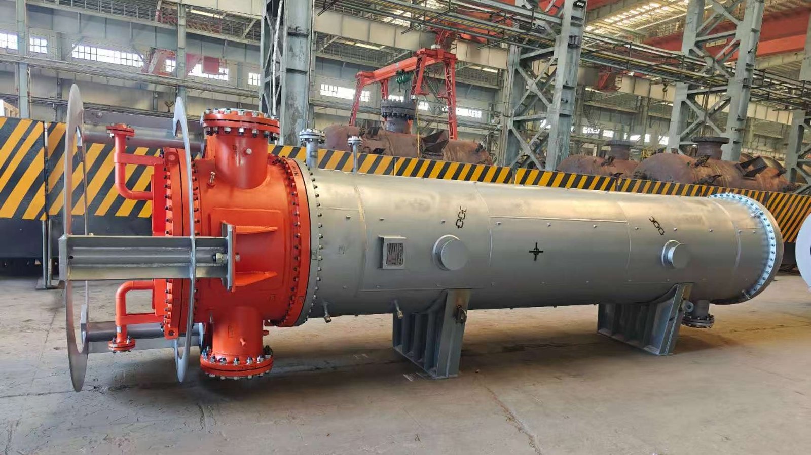
For a new industrial shell-and-tube exchanger, the manufacturer can evaluate an approved process and mechanical specification and clarify the agreed fabrication and documentation requirements.
The company’s industrial shell-and-tube heat exchanger product range provides a starting point for discussing complete heat-exchanger equipment.
To support an engineering enquiry, provide the required process duty, fluid conditions, pressure and temperature requirements, approved materials, applicable standards, current-equipment information, and a clear statement of why replacement is being evaluated.
This is a complete-equipment procurement discussion, not an offer of stand-alone tube-plugging, gasket replacement, or inspection services.
Frequently Asked Questions
Can a change in outlet temperature alone prove that a heat exchanger has failed?
No. Outlet temperature depends on the flowrates, inlet conditions, fluid properties, utility supply, operating configuration, and actual equipment performance. The engineer should compare technically equivalent conditions before attributing a temperature change to fouling or equipment damage.
Does a higher heat exchanger pressure drop always mean fouling?
No. Pressure drop can change with flowrate, viscosity, phase behavior, instrumentation, valve conditions, or internal restrictions. A trend is more meaningful when evaluated against comparable operating conditions and supporting evidence.
How can an owner identify a possible internal tube leak?
Possible indications include unexpected cross-stream contamination, changes in relevant fluid-analysis results, or material-balance discrepancies. These findings are not always unique to a tube leak. The facility’s responsible team should determine appropriate verification and safety actions under approved procedures.
What are the common causes of industrial heat exchanger failure?
Depending on service, causes or contributors can include fouling, scaling, corrosion, erosion, vibration damage, thermal fatigue, joint leakage, and changed process conditions. A confirmed diagnosis requires evidence consistent with the suspected mechanism.
What is the average life of a shell-and-tube heat exchanger?
There is no universally reliable service-life figure for all industrial exchangers. Actual longevity depends on metallurgy, process chemistry, operating conditions, damage mechanisms, inspection, maintenance, and changes in the required duty. Age alone should not decide whether a unit is fit for continued service.
What information should be included in a heat exchanger condition assessment?
Useful inputs include comparable operating trends, original design records, current process data, sampling results, maintenance history, qualified inspection reports, and unresolved technical questions. The responsible engineering team should determine whether further examination or analysis is needed.
When should a heat exchanger be repaired rather than replaced?
The decision depends on confirmed equipment condition, applicable requirements, technical repair feasibility, expected performance, recurring damage risks, and project-specific economics. There is no universal repair-cost ratio or tube-damage percentage that determines the correct decision for every exchanger.
Conclusion
Industrial heat exchanger failure signs should be treated as evidence to investigate, not as automatic proof of a single failure mechanism.
A lower outlet temperature or changing pressure drop may reflect fouling, but it may also reflect altered process conditions, utility limitations, instrument error, or internal flow behavior. Leakage and mechanical damage require a separate integrity-focused assessment, even when thermal performance appears acceptable.
For a defensible repair-versus-replacement decision, the owner should bring together comparable operating data, fluid analysis, inspection findings, original equipment records, and a qualified review of unresolved risks.
The objective is not to apply a universal failure threshold. It is to establish what has changed, what the available evidence actually proves, and whether the current exchanger can safely and economically satisfy the required service.
When complete replacement is being considered, a clear evidence package enables the EPC team and manufacturer to specify a suitable industrial exchanger without repeating the original problem or relying on unverified assumptions.
References
- Heat Transfer Research, Inc. (HTRI). Hendrix, F. (September 7, 2026). Connecting the Dots: Elevate Exchanger Performance Monitoring with HTRIconnect. Discusses combining historical plant data with exchanger simulations to support performance monitoring and maintenance decisions. https://www.htri.net/news/connecting-the-dots-elevate-exchanger-performance-monitoring-with-htriconnect
- HTRI. (2022). Keynote: Troubleshooting Heat Exchangers for Environmental Technologies. Public abstract discussing fouling, maldistribution, vibration, and thermal performance limitations. https://www.htri.net/horizons/overview/keynote–troubleshooting-heat-exchangers-for-environmental-technologies
- U.S. Occupational Safety and Health Administration (OSHA). OSHA Technical Manual, Section IV, Chapter 2: Petroleum Refining Process. Technical background on refinery heat-exchanger hazards, internal leakage, and consequences for connected systems. https://www.osha.gov/otm/section-4-safety-hazards/chapter-2
- Society for Maintenance & Reliability Professionals (SMRP). Alkhuliawi, F. (June 2021). Practices for Maintaining the Availability of Plant Heat Exchangers. Industry maintenance article discussing degradation, inspection, and operating-condition influences. https://smrp.org/news/solutions-archive/practices-for-maintaining-the-availability-of-plant-heat-exchangers/
- Inspectioneering Journal. Gysbers, A. C. (2015). Gathering & Analysis of Heat Exchanger Tube Inspection Thickness Data. Discusses limitations of tube inspection coverage and interpretation of wall-thickness results. https://inspectioneering.com/journal/2015-04-21/4542/gathering-and-analysis-of-heat
- American Petroleum Institute (API). New Edition of API 510 Enhances Safety of Pressure Vessel Inspection Code. Publisher overview of in-service pressure vessel inspection, repair, alteration, and assessment. This article does not reproduce the paid standard. https://www.api.org/products-and-services/standards/important-standards-announcements/tradeannouncement-api510
- American Society of Mechanical Engineers (ASME). PCC-2: Repair of Pressure Equipment and Piping. Official standards description covering pressure-equipment repair methods and the distinction between repair methods and prior inspection or flaw assessment. https://www.asme.org/codes-standards/find-codes-standards/repair-of-pressure-equipment-and-piping