
Executive summary. When the hot side of an operating heat exchanger appears to release more heat than the cold side absorbs—or the reverse—the difference is a heat-balance mismatch, not an immediate verdict that the exchanger is undersized. Before approving additional surface area, a retube, or a replacement shell-and-tube exchanger, industrial owners and EPC teams should establish a common equipment boundary, compare synchronized and sufficiently stable measurements, verify the flow and temperature data, and use fluid properties appropriate to the actual states and compositions. Phase changes, bypasses, heat exchange with the surroundings, transient energy accumulation, and measurement uncertainty can all affect the comparison.
The practical procurement question is therefore not simply “Which duty number should we trust?” It is “What evidence would make a current-performance assessment credible enough to support a new equipment specification?” This guide provides a step-by-step data-reconciliation path, a buyer’s operating-data register, and an RFQ handoff checklist for complete industrial heat exchangers. It does not set a universal permissible mismatch percentage, certify an existing exchanger’s performance, or substitute for site engineering and process-safety review.
1. What Does a Hot-Side/Cold-Side Heat-Balance Mismatch Actually Mean?
A shell-and-tube heat exchanger transfers energy between two separated process streams. If the control volume is the entire exchanger, the streams are at steady state, there are no unaccounted streams or significant external heat exchanges, and stored energy is not changing, the heat released by the hot side and absorbed by the cold side should be consistent within the uncertainty of the measurements and property calculations.
For a single inlet and outlet on each side, define positive magnitudes as:
where ṁ is mass-flow rate and h is specific enthalpy at the stated stream condition. In a simplified, single-phase service with an appropriate constant or mean heat capacity, the familiar approximation is:
The enthalpy form is more general. It is necessary to account for latent heat when a stream condenses, evaporates, or changes its phase fraction; the constant-cₚ temperature-difference shortcut should not be applied across a phase transition. The U.S. Department of Energy’s Thermodynamics, Heat Transfer, and Fluid Flow handbook distinguishes these expressions in its discussion of open-system energy balances. See the DOE fundamentals handbook, Volume 1 (1992, thermodynamics section).
Define the boundary before interpreting the difference
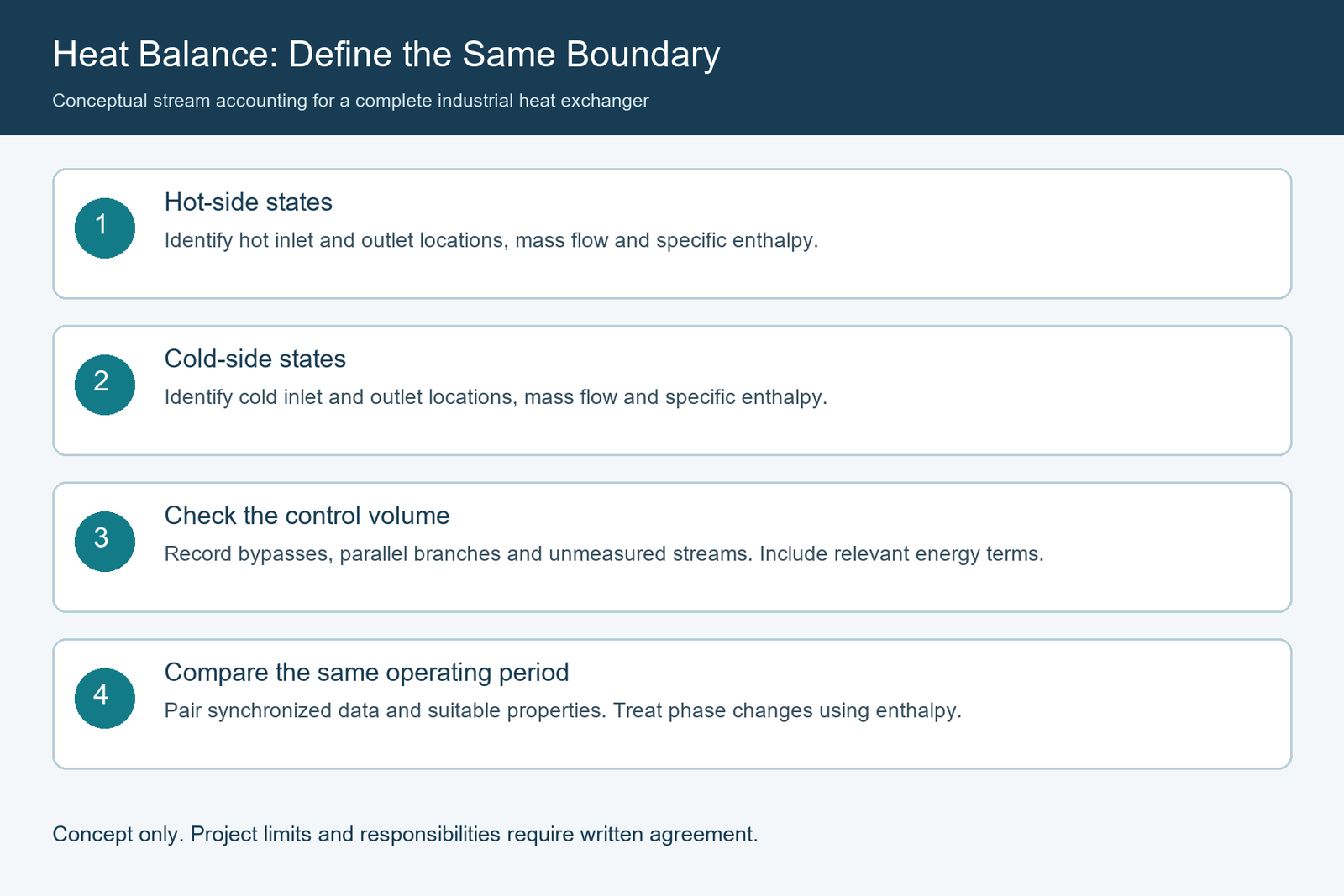
The word exchanger can mean different boundaries on a plant drawing and in a supplier’s rating report. One calculation may use nozzle-to-nozzle conditions, while another uses sensors several meters away from the nozzles, after piping branches, an inlet mixer, a return header, or a control bypass. Those calculations may not describe the same physical equipment.
Record exactly where four primary stream states are defined: hot inlet, hot outlet, cold inlet, and cold outlet. Then identify whether any measured flow includes an exchanger bypass, recirculation line, vent, drain, quench connection, or second exchanger operating in parallel. If the control volume has more than one inlet or outlet, use an appropriate multi-stream mass and energy balance, not four-point equations that omit a stream.
A full steady-state accounting may also need external heat transfer or other energy terms. During a transient, the rate of energy storage in the metal and fluids can be important. The two separately calculated duties are comparable only when their boundary and assumptions are compatible.
A mismatch is not the same as a shortage of heat-transfer area
These are distinct questions:
| Question | What it assesses | Evidence needed |
|---|---|---|
| Are the two stream energy balances consistent? | Data quality and completeness of the energy accounting | Compatible boundaries, synchronized mass flows, temperatures, properties and uncertainty |
| Does the existing exchanger transfer the required amount of heat? | Actual operating duty against a justified target | Reconciled operating state, process requirement and appropriate thermal rating |
| Is the exchanger physically too small? | Capability of its geometry and configuration under the future duty | Validated operating basis, mechanical data and thermal/hydraulic assessment |
| Has fouling reduced performance? | Change in heat-transfer resistance or hydraulic behavior under comparable conditions | Credible operating trends, clean/reference rating, fouling and inspection evidence |
An unreliable heat balance can distort all the subsequent evaluations. Nor does closure by itself prove the equipment meets the required duty: both streams might agree on a heat-transfer rate below the plant’s target because the utility temperature, throughput, or other operating condition has changed.
2. Are the Hot- and Cold-Side Data From the Same Stable Operating Period?
Time alignment is the first practical check. A spreadsheet assembled from the latest available readings can mix measurements recorded at different times. The hot-side flow may be yesterday’s laboratory-adjusted value, the cold-side temperature a present historian trend, and the utility flow a shift average. A mathematical result from that collection is not a defensible snapshot of one operating state.
HTRI’s public description of its Edgeview trend-analysis approach emphasizes time-based operating data, unit conversion, filtering and removal of gross errors before using calculated performance indicators. This supports a useful workflow principle; it does not imply a buyer must license HTRI software or that any particular data-cleaning rule is universally required.
Build a synchronized data window
For each intended evaluation case, capture the following information together:
- Clock and time zone: confirm whether the historian, laboratory system and local instruments share a time basis; record any known timestamp offsets.
- Sampling and aggregation: identify instantaneous readings, time averages, totalizer-derived averages and lab samples. Avoid comparing an instantaneous flow with a temperature averaged over a substantially different window without justification.
- Residence and instrument response: account for process transport delay between exchanger nozzles and sensors and for sensors or analyzers that respond more slowly than the process.
- Operating context: log production rate, valve positions, controller mode, steam or cooling-water supply changes, bypass position, maintenance interventions and parallel-unit status.
- Uncertainty and validity: flag instrument faults, out-of-range measurements, frozen tags, substitutions, manual overrides and questionable lab samples.
A practical field name is Case ID + start/end timestamp + sample interval + data quality flag. The analyst should retain the raw readings as well as any processed averages so that changes remain traceable.
Decide whether the system was genuinely steady
A stable-looking outlet temperature is insufficient if flow, composition, pressure, vapor fraction or the other side’s conditions are changing. At startup, after a large flow step, or when a condenser is filling or draining, the exchanger’s metal and fluid inventories can store or release energy. Even when one outlet temperature looks flat, an internal inventory or control system may still be adjusting.
Ask the process engineer to document the criteria for selecting representative windows. Appropriate criteria depend on response times, the plant process, whether the duty is continuous or batch, the available instruments, and the purpose of the assessment. There is no universal stable-period duration in this article.
If the service is inherently transient, analyze it as such. A batch heating cycle or cyclic duty may call for time-integrated energy accounting, a dynamic model, or additional sensors. It should not be forced into a steady-state comparison merely because four temperatures are available.
A simple time-misalignment example
Illustrative situation only; no plant data or performance claim is implied. Suppose the cold-side flow increases while the hot-side control valve is still responding. The cold-side inlet and outlet temperatures recorded just before the change and the hot-side temperatures recorded afterward can yield different calculated duties, even if each sensor is functioning. Aligning all measurements to a common interval, and then assessing whether the system has settled, is essential before drawing a conclusion about exchanger condition.
3. Which Flow and Temperature Measurements Should Be Verified First?
Flow and temperature are often the strongest immediate influences on a calculated sensible-heat duty. A credible evaluation does not require every sensor to be replaced; it requires the buyer to know what each measurement represents and what evidence supports its use.
Mass flow is not the same as volumetric flow
The heat-duty expressions use mass flow. A field tag may report volume per hour, standard volume, actual volume, or a calculated mass rate. The conversion cannot be assumed without checking the fluid and reference state:
where density ρ must correspond to the relevant conditions of the reported actual volumetric rate. Standardized gas flow requires its defined reference pressure, temperature, gas composition and conversion conventions; it is not interchangeable with an actual volume rate.
Check the meter’s installation and calculation basis: fluid type, density or compensation input, meter factor, pressure/temperature correction, upper and lower measurement limits, recent verification, and whether the device measures a combined stream or only the flow actually passing through the exchanger.
For variable-composition hydrocarbon mixtures, glycol solutions or concentrated process liquids, using the density of clean water or a previous feed formulation can create an avoidable error in the duty calculation. A mass-flow output derived from a faulty density or composition input is not automatically more reliable than a raw volumetric measurement.
Temperature must correspond to the actual stream state
For each inlet and outlet temperature, check:
- Location: whether the instrument is near the specified exchanger connection and is upstream or downstream of any mixing, bypass or parallel equipment.
- Process representation: whether the measurement captures a well-mixed bulk stream rather than a stratified region, wall temperature or partially filled pipe condition.
- Sensor health: tag identity, calibration and maintenance history, measurement range, known bias, thermowell arrangement and any compensations.
- Temporal match: reading time, filtering or damping, and response time relative to the companion measurements.
- Physical state: pressure and phase condition at the measurement location, especially near saturation or flashing.
When the temperature change across the exchanger is small, a modest bias in either of the two readings can materially distort the difference used in the heat-duty calculation. That is a reason to evaluate the measurement chain, not to prescribe a single temperature-sensor accuracy for every installation.
Request this four-point measurement register
| Required entry | Hot inlet | Hot outlet | Cold inlet | Cold outlet |
|---|---|---|---|---|
| Tag and physical location (P&ID / isometric) | Record | Record | Record | Record |
| Timestamp or common analysis window | Record | Record | Record | Record |
| Measured temperature and units | Record | Record | Record | Record |
| Pressure or relevant state indicator | Record | Record | Record | Record |
| Flow measurement location and basis | Define side flow | Confirm stream/bypass boundary | Define side flow | Confirm stream/bypass boundary |
| Composition / phase / sample source | Identify | Confirm any change | Identify | Confirm any change |
| Instrument status and traceability | Attach | Attach | Attach | Attach |
| Known data limitation | State | State | State | State |
The buyer should also provide the instrument list, P&IDs and simplified flow schematic. Those documents allow the analyst to determine whether apparent mass-flow discrepancies are caused by the measurement boundary rather than by a fault inside the exchanger.
4. Do the Fluid Properties and Phase Assumptions Match the Actual Process?
A heat balance can be numerically precise and thermodynamically wrong if it uses inappropriate fluid properties. The required property basis depends on composition, pressure, temperature, phase and, for mixtures, the property method and its validity range.
Check composition before selecting a heat capacity
For straightforward single-phase service with a modest temperature range and well-characterized fluid, an accepted mean heat capacity may be adequate for a screening calculation. For a wide temperature range or a temperature-dependent mixture, calculate the enthalpy difference using a suitable property model or integrated heat capacity rather than assuming constant cₚ.
The NIST Chemistry WebBook’s fluid-property service illustrates how density, heat capacity and enthalpy depend on the chosen thermodynamic state. Its tabulated data cover a selected set of pure fluids; they are not a universal substitute for validated properties of every proprietary chemical mixture.
For industrial enquiries, record the following separately for both sides:
| Property input | Questions for the process/EPC team | Why it matters |
|---|---|---|
| Fluid name and full composition basis | Which components, concentration units and variability are represented? | Changes molecular weight, heat capacity, density and phase behavior |
| Inlet and outlet pressure | Absolute or gauge? Local pressure or upstream header? | Influences thermodynamic state and potential flashing or condensation |
| Temperature range | Which conditions were used to calculate properties? | A single property value may not cover the duty interval |
| Phase description | Liquid, vapor, mixed phase, boiling, condensing or flashing? | Determines whether latent heat and phase fractions are needed |
| Property source or model | Laboratory, approved simulator, literature or engineering estimate? | Enables independent review and consistency |
| Data confidence and revision | Is it measured, validated, approximate or pending? | Prevents false precision in a bid comparison |
Phase change requires an enthalpy-based treatment
In a condenser, the vapor may release substantial latent heat while its saturation temperature changes little. In a reboiler, a liquid may absorb energy while vapor forms. Neither case can be evaluated reliably by multiplying a single-phase cₚ by an inlet-to-outlet temperature difference across the full phase-change region.
Provide inlet and outlet vapor fractions where applicable, pressure, composition, noncondensable-gas information where material, and an approved enthalpy source. Ensure the two sides’ enthalpy calculations use consistent composition and thermodynamic reference conventions; the physically relevant quantity is each stream’s enthalpy difference, not its arbitrary zero of enthalpy.
A property package should be accepted by the responsible process engineer before it is used to justify a large capital decision. HTRI’s existence and other vendors’ simulation capabilities are not evidence that a particular exchanger manufacturer owns those tools or can guarantee plant-wide process calculations.
Check for changes occurring between measurement points
If a process stream can flash after the exchanger outlet, mix with another stream before a sensor, condense in piping, or change composition because of a process interaction, the temperature measured beyond that event should not automatically be treated as the exchanger outlet state. The energy balance must follow the selected physical boundary and include the actual phases and streams.
5. Could the Discrepancy Be Physical Rather Than a Data Error?
Poor measurements are common candidates, but a mismatch should not be automatically “corrected away.” A sound review separates known physical energy terms from uncertain or faulty readings and documents the evidence for each hypothesis.
External heat loss or gain
A hot, imperfectly insulated shell and adjacent piping can lose energy to the surroundings; a cold exchanger may gain it. If the measurement boundary includes substantial piping or exposed equipment, that contribution can be relevant. Its magnitude must be supported by a site-specific calculation or assessment, not assumed to explain whatever difference remains. The physical energy balance can include an external heat-transfer term when justified.
Unmeasured side streams, bypasses and leakage
Look for:
- a bypass or recirculation path that changes the fraction of metered flow actually crossing the heat-transfer surface;
- parallel exchangers or shared manifolds that contaminate a four-point data set;
- additional nozzles, quench, vent, drain or intermittent streams omitted from the chosen boundary;
- mixing downstream of the outlet sensor location assumed in the rating calculation;
- any suspected cross-leakage between streams, which would demand a separate process-integrity and safety investigation.
A cross-leakage concern should be escalated under the site’s approved integrity procedures. A spreadsheet heat-balance mismatch is not a safe or sufficient diagnostic test for tube failure; chemical composition, pressure behavior and appropriate examination may be needed.
Energy accumulation and control transients
During startup, shutdown, batch cycles, rapid utility changes or changing liquid levels, metal and internal fluid inventories may be gaining or releasing energy. A simple steady-state equality omits that storage term. If the plant cannot produce a sufficiently stable interval, the project should either collect a suitable period or commission a documented transient assessment appropriate to the equipment and process.
Fouling and maldistribution: possible performance causes, not automatic balance errors
Fouling can reduce a heat exchanger’s achievable duty at given flow and inlet conditions; flow maldistribution or mechanical damage can also affect performance. But for a physically well-accounted steady exchanger with negligible external exchange, the energy lost by one process stream still goes to the other. Fouling alone does not justify declaring that one correctly calculated side must show a different heat-transfer rate from the other.
Investigating a genuine performance shortfall may involve pressure-drop trends, fouling history, operating flow regime, condition of the bundle and an appropriate thermal rating. Such work follows, rather than replaces, the basic energy-data review. For the separate contractual question of guaranteed duty and acceptance conditions, see our shell-and-tube heat exchanger performance guarantee guide.
6. How Should Buyers Review Mismatch and Measurement Uncertainty Without a Universal Percentage?
A convenient reporting figure is the signed duty difference, ΔQ̇ = Q̇ₕ − Q̇꜀, with both duties defined as positive magnitudes. An organization may also define a relative difference, but it must disclose the denominator and sign convention, since different denominators produce different percentages. Neither measure by itself establishes a failure threshold.
Trace uncertainty back to its inputs
Each calculated duty depends on flow and inlet/outlet enthalpies or temperatures. The relevant uncertainty sources can include:
- flow-meter measurement and any density or composition compensation;
- temperature measurement, sensor location and the difference between two temperatures;
- sampling mismatch, time alignment and transient variation;
- thermodynamic-property model limitations and composition uncertainty;
- correlations and shared sources of bias between the two sides or between measured inputs;
- unmeasured branches, missing heat-transfer terms and model assumptions.
NIST Technical Note 1297 describes how components of measurement uncertainty are combined, including covariance where appropriate; recognized systematic effects should be addressed rather than assumed away. See NIST guidance on combined standard uncertainty.
It would be unsound to state that every heat exchanger must close within a prescribed percentage. An appropriate decision criterion depends on the instruments, fluid states, the intended engineering conclusion, and any applicable project test or acceptance procedure. An uncertainty estimate should be traceable to the measurements and models actually used—not a round number appended after the result is known.
Do not manufacture closure by forcing one side to match the other
The purpose of reconciliation is not to make an inconvenient discrepancy disappear. The analyst should first identify gross errors, check instrument calibration and property methods, and reconcile measurements subject to valid conservation constraints and documented uncertainty. Adjusted estimates need a recorded method, retained raw data and named approvals. If material streams or losses are missing, forcing equality can produce plausible-looking but incorrect values.
The IEA/SINTEF process-integration primer discusses the need to reconcile plant measurements when assessing retrofit heat recovery, because relying on inconsistent measured heat extraction and absorption can lead to unrealistic retrofit conclusions. This is a general retrofit-data principle, not an endorsement of one exchanger’s performance or a mandatory acceptance standard.
An example of two different decisions
Conceptual comparison, not a measured project or numerical guarantee:
Case A — data not ready for design. An exchanger’s cold-side outlet reading is recorded at the end of a utility-flow change, while the hot-side flow is a preceding shift average. The composition basis is outdated, and the outlet temperature sensor lies downstream of a bypass mixer. The calculated mismatch may be large, but the first action is data correction and a new representative measurement window, not an equipment purchase.
Case B — ready for thermal reassessment. Both sides have synchronized mass-flow and temperature/pressure data from the same approved operating window, consistent fluid properties, verified sensor boundaries, and a documented uncertainty assessment. The reconciled duty is below an approved process target under the operating cases of concern. That result justifies thermal/hydraulic assessment of the existing exchanger and alternatives, but not an automatic conclusion that replacement is the only remedy.
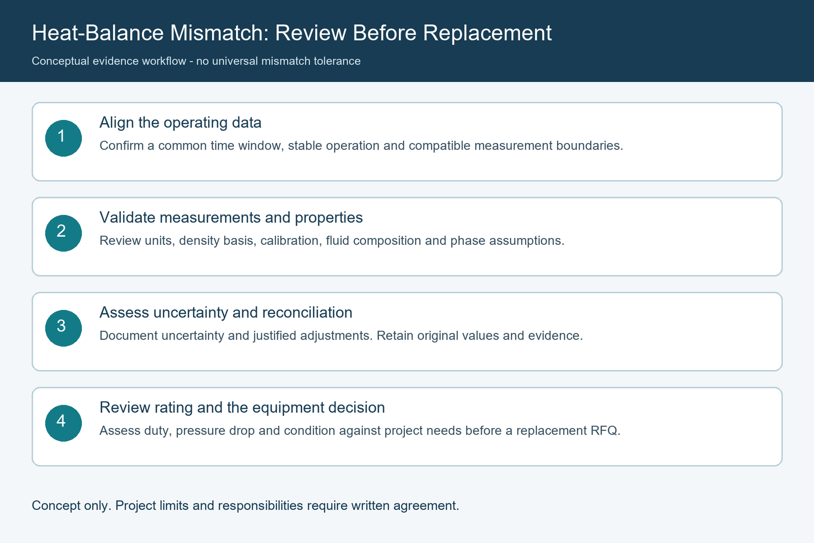
7. When Is There Enough Evidence to Consider Resizing or Replacing the Entire Exchanger?
Once the operating data are defensible, the owner and responsible thermal designer can compare the actual operating point with the original design basis and the plant’s future requirements. The key distinction is data reconciliation first; equipment rating and procurement decisions second.
A staged decision path
| Review gate | Minimum question to resolve | Next step if unresolved |
|---|---|---|
| 1. Equipment boundary | Do measured conditions correspond to the same exchanger, nozzles and flow paths? | Verify P&IDs, instrumentation and bypass arrangements |
| 2. Simultaneity and stability | Are hot- and cold-side measurements representative of the same case? | Repeat measurement or perform an approved transient analysis |
| 3. Flow and temperature quality | Are units, flow bases, meter health and sensor locations defensible? | Review instrumentation data and calibration evidence |
| 4. Properties and phases | Are composition and enthalpy calculations fit for the process states? | Resolve laboratory/property data and process-model assumptions |
| 5. Energy accounting | Are external exchanges, secondary streams and uncertainty evaluated? | Complete/reconcile the stated control-volume balance |
| 6. Required process duty | Is there an approved, relevant operating target for the plant’s present and future conditions? | Obtain process-engineering approval of the duty envelope |
| 7. Exchanger capability | Can the existing geometry meet required duty and pressure-drop limits under the approved basis? | Request documented thermal/hydraulic rating and mechanical review |
| 8. Procurement choice | Are cleaning, repair, operating changes, debottlenecking, resizing and replacement compared on a common basis? | Clarify scope, risk, outage requirements and project responsibility |
No single outlet-temperature observation is sufficient to pass these gates. The plant may be operating at hotter cooling-water supply conditions, an altered product mix or a changed throughput. The original exchanger could be within its approved design capability and still fail to achieve an outlet temperature that was never part of the original duty envelope. Conversely, a unit may have inadequate capability for a new service even if a snapshot heat balance closes perfectly.
What the complete replacement/RFQ data package should contain
For an EPC or owner preparing to seek a custom shell-and-tube exchanger, provide these items as a unified, version-controlled package:
| Deliverable | Required content | Main source / approval |
|---|---|---|
| Existing equipment identity | Tag number, duty description, orientation, configuration, drawings, datasheets, nameplate and applicable mechanical constraints | Owner equipment records / mechanical team |
| Boundary schematic | Marked P&ID and sketch showing actual exchanger inlets, outlets, measurement points and bypass/parallel flows | Process and instrumentation teams |
| Raw time-series data | Timestamped temperatures, pressures, actual flow records, controller/valve states and data-quality flags for both sides | Operations / historian custodian |
| Approved analysis windows | Case IDs, sampling method, steady-state evidence, excluded intervals and reason for exclusion | Process engineering |
| Fluid and property basis | Stream compositions, property sources, enthalpy/phase method, concentrations, lab samples and uncertainty where material | Process engineering / laboratory |
| Reconciled heat balance | Separate hot-side and cold-side duties, sign/units, boundary assumptions, losses and uncertainty statement | Qualified process/thermal reviewer |
| Original design basis | Approved duty, clean/fouled thermal assumptions, both-side pressure-drop limits and original rating if available | Project archives / original designer |
| New duty envelope | Minimum, normal, maximum, seasonal and expected future services; agreed acceptance targets | Owner / EPC process authority |
| Integrity and maintenance | Cleaning history, inspection/repair records, fouling evidence and relevant mechanical limitations | Maintenance / mechanical integrity |
| Commercial scope and interface | Who supplies rating, thermal-design responsibility, mechanical fabrication scope, site data and acceptance testing; schedule and documentation | EPC procurement and participating suppliers |
Where the plant requires an independent performance assessment, the owner should define the responsible qualified engineer or service provider. A manufacturing quotation should not silently imply that the fabricator can reconstruct every plant-side measurement, own the process model, or accept an unbounded performance guarantee.
The manufacturer’s role can then be appropriately defined: evaluate the supplied technical basis for a complete industrial shell-and-tube heat exchanger, identify assumptions and exclusions, confirm the proposed scope of thermal design versus mechanical fabrication, and provide the agreed drawings, technical documents, examinations and delivery scope. Any additional testing or process performance obligation requires specific confirmation.
Keep existing-condition evidence distinct from future-duty assumptions
Avoid combining an observed low-flow condition, a maximum future production rate, and an old clean-condition rating as if they formed one tested operating point. Use separate case IDs for as-operated, current required, and future design conditions. The responsible engineer should decide how the existing unit’s performance may be corrected or rated across those cases and where extrapolation is no longer defensible.
Also distinguish these outcomes:
- Measure again: when the balance cannot be trusted because essential instrumentation, boundaries or properties are missing.
- Investigate/maintain: when credible trends support an operating, fouling or integrity issue that may be corrected without resizing.
- Re-rate the existing unit: when available geometry and records permit a technically supported evaluation against changed duty.
- Consider replacement or expansion: when an approved assessment finds the present equipment or operating arrangement unsuitable for the required duty, or when other life-cycle or project constraints justify the change.
The selection is project-specific. This article does not promise that cleaning, a particular redesign, or purchasing a larger exchanger will achieve the desired production outcome.
8. What Should Be Written Into the Technical Clarification Before RFQ Approval?
Buyers can convert the data review into a concise set of documented questions. Request written answers before treating a vendor’s thermal proposal as directly comparable with an alternative.
- Boundary and cases: Which physical nozzles and operating cases were used for the current and proposed heat balances?
- Data vintage: Do all principal temperatures, flows and pressures refer to the same approved measurement windows?
- Mass-flow basis: Are the rates actual mass flow, actual volumetric flow or standardized volume; how were density and composition used?
- Property model: Which fluid compositions, enthalpy sources and phase assumptions were approved for each side?
- Open data issues: Which readings were rejected or adjusted, what evidence supports that decision, and who authorized it?
- Balance statement: How do hot-side and cold-side duties compare after known external exchanges and material branches are addressed? What uncertainty is associated with the result?
- Present operating requirement: What is the true approved process duty at the current inlet conditions, not simply the original design-nameplate number?
- Future envelope: Which future cases require additional capacity, and which are information-only?
- Pressure-drop and operability: Has the assessment evaluated both sides’ pressure drop, available utility conditions, controllability and practical operating constraints?
- Existing mechanical limits: Which original drawings, material records, inspection data and equipment constraints are available or missing?
- Supplier responsibility: Does the offer include thermal rating/design, mechanical design and manufacture, or fabrication only to third-party drawings? Who approves the calculations?
- Acceptance boundary: Which factory and site checks are included, how will operating deviations be handled, and which party provides measurement evidence?
For complex services, the answers may require the owner, process licensor, EPC and exchanger manufacturer to collaborate. The supplier should state assumptions and deviations rather than turning unknown feed properties or an unresolved heat balance into an unconditional capacity promise.
FAQ
Can an outlet temperature alone prove that a heat exchanger is underperforming?
No. Outlet temperature depends on inlet conditions, mass flow, composition, utility supply, control behavior and the actual duty requirement. Compare both sides’ consistent operating data and the relevant approved target before attributing the result to exchanger capability.
Is every heat-balance mismatch evidence of fouling?
No. Fouling may reduce achievable duty, but a hot/cold balance difference can arise from non-synchronized readings, flow conversion errors, property assumptions, phase behavior, unmeasured streams, external exchanges and uncertainty. Fouling needs additional evidence under comparable operating conditions.
Should the hot-side or cold-side calculated duty be used for sizing?
Neither should be selected automatically. Investigate the discrepancy, establish a defensible common basis and document any uncertainty. The final design duty must be approved for the required process cases; simply choosing the larger calculated number is not a substitute for reconciliation or process design.
What if the exchanger condenses vapor or boils liquid?
Use a property and enthalpy method that handles the relevant phase states and fractions. The single-phase ṁ cₚ ΔT shortcut across the entire phase-change zone can omit latent heat and produce a misleading balance.
Is there a standard percentage by which the two duties must agree?
Not one that is valid for every exchanger and every procurement decision. The evaluation criterion depends on the application, applicable test method, measuring instruments, uncertainty and project agreement. Disclose the method, denominator and decision basis rather than inventing a blanket threshold.
How long should an exchanger operate before taking balance measurements?
There is no universal duration. Define a representative time window using the process response, stability of flow/temperature/pressure/composition and the intended assessment. Transient services may require a different method altogether.
Does a closed heat balance prove that a replacement exchanger is unnecessary?
No. Closure supports confidence in the energy accounting under the tested conditions. It says nothing by itself about whether the duty is sufficient for a new throughput target, whether the pressure drop is acceptable or whether the existing vessel meets future mechanical and maintenance requirements.
What is the minimum useful submission to a potential manufacturer?
Provide an approved exchanger datasheet, existing equipment drawings, synchronized two-side operating data, fluid composition and property basis, a clearly stated duty envelope, and a summary of unresolved measurement issues. Identify whether the enquiry requests only mechanical fabrication or also thermal engineering and a defined performance obligation.
Conclusion: Trust the Energy Balance Before Buying More Heat-Transfer Area
A heat-balance mismatch is a prompt to check the evidence, not a standalone replacement trigger. Define the correct exchanger boundary; synchronize and qualify the operating period; verify flow, temperature and composition; use suitable enthalpy calculations; then address physical losses, bypasses, energy storage and measurement uncertainty. Only after this groundwork can an owner or EPC fairly judge whether the existing exchanger needs maintenance, re-rating, debottlenecking or replacement.
For a complete industrial shell-and-tube exchanger enquiry, submit your approved design datasheet, the two-side operating-data package, a marked measurement-boundary schematic, fluid-property information and the future-duty requirements. These are the starting point for discussing a technically supportable equipment proposal, including the scope and assumptions that the manufacturer can actually accept.
References
- U.S. Department of Energy. DOE Fundamentals Handbook: Thermodynamics, Heat Transfer, and Fluid Flow, Vol. 1, DOE-HDBK-1012/1-92 (June 1992). General control-volume energy balance and enthalpy versus single-phase heat-capacity treatment. https://www.energy.gov/sites/default/files/2026-04/DOE-HDBK-1012-92_VOL1.pdf
- Heat Transfer Research, Inc. (HTRI). Edgeview® public product overview. Time-based process-data filtering, unit treatment and heat-exchanger performance trending; product description is not a universal test/closure criterion. https://www.htri.net/edgeview
- National Institute of Standards and Technology (NIST). Chemistry WebBook: Thermophysical Properties of Fluid Systems. State-dependent property data for a selected group of fluids; not a property guarantee for arbitrary process mixtures. https://webbook.nist.gov/chemistry/fluid/
- NIST. Technical Note 1297, Section 5: Combined Standard Uncertainty. Uncertainty propagation, correlation and systematic-effect considerations. https://www.nist.gov/pml/nist-technical-note-1297/nist-tn-1297-5-combined-standard-uncertainty
- SINTEF Energy Research / International Energy Agency (IEA) Process Integration Implementing Agreement. A Process Integration Primer (2000), retrofit-data discussion. Historical, educational guidance on reconciling operating measurements before retrofit decisions. https://pubdb.bfe.admin.ch/en/publication/download/1401
- ASME. PTC 12.5 — Single Phase Heat Exchangers (2000, R2025), official public scope description. This scope is specific to single-phase heat exchangers and does not establish one universal heat-balance tolerance or the requirements for phase-change services. https://www.asme.org/codes-standards/find-codes-standards/single-phase-heat-exchangers