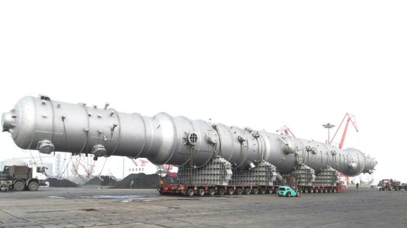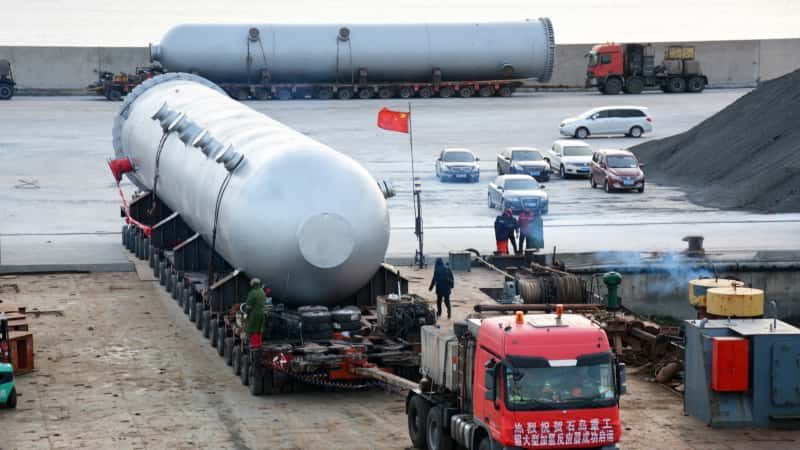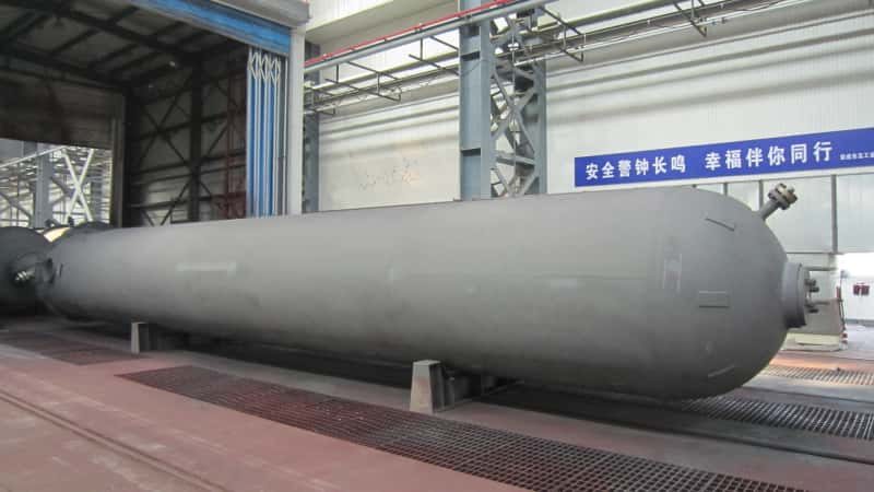

A three-phase separator should not be specified from one nameplate flow rate or a single turndown ratio. For a variable-feed service, the EPC process team needs to define credible combinations of gas, light-liquid and heavy-liquid flow, along with the pressure, temperature, fluid properties and outlet-quality requirements that apply to each combination. The minimum gas rate does not necessarily occur with the minimum oil or water rate; the peak total feed may not be the most difficult oil–water separation case.
For buyers preparing a three-phase separator turndown operating-cases package, the practical deliverable is an approved case matrix, not a generic vessel-sizing calculation. It should tell the equipment designer which conditions are sustained, which are short-lived, what performance is required in each case, and who owns unresolved assumptions. This guide focuses on that process-data handover for complete industrial separator vessels.
What Does the Operating Envelope Need to Establish?
The operating envelope defines the combinations of conditions under which the separator is expected to perform a stated duty. It is different from the vessel’s mechanical design pressure and temperature limits, which must be established and verified separately under the project’s applicable construction code.
For three-phase duty, the process envelope needs at least three distinguishable streams: gas, light liquid (often oil or condensate), and heavy liquid (often water). Each operating case should describe simultaneous phase rates, not three unrelated maxima copied from separate production forecasts.
Define the basis of each flow rate
A value such as “gas flow: 100” has no engineering meaning without units and a reference basis. Identify whether the gas rate is stated at standard or actual flowing conditions, and specify the standard conditions if used. For each liquid, state whether the figure is a mass rate or a volumetric rate at defined conditions. The responsible process engineer should confirm that phase rates, compositions and fluid properties refer to the same process state.
A single ratio such as “5:1 turndown” is also ambiguous unless the numerator, denominator and performance boundary are identified. Gas turndown, oil-flow turndown and water-flow turndown are not interchangeable; neither is a rate range proof that every point in that range meets outlet specifications.
Do not combine independent extremes without a process basis
It may be conservative to ask about high gas load and high liquid level together, but treating every extreme as simultaneous can also create an artificial, physically impossible case. Conversely, assuming that all phase rates decline together can omit a credible low-gas/high-water condition. The owner or EPC should identify credible combinations from the process model, operating philosophy, production forecast or upstream system study. When a combination is uncertain, label it unconfirmed rather than silently treating it as design-approved.
Which Minimum, Normal and Peak Cases Should the Datasheet Include?
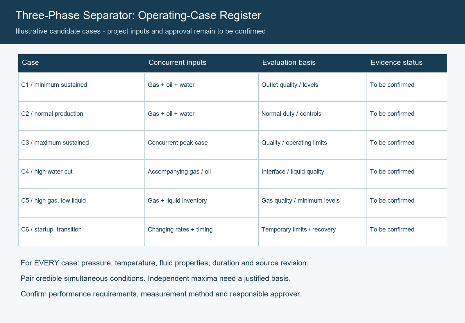
Use a numbered matrix that can be cross-referenced in process calculations, the equipment datasheet, the supplier’s technical proposal and the final review record. The following is a template for defining cases, not a claim that every project needs all of them.
| Candidate case | Combined inlet condition to specify | Decision or acceptance boundary |
|---|---|---|
| C1 — Minimum sustained production | Simultaneous gas, oil and water rates; pressure, temperature and phase properties at sustained low load | Required outlet quality and stable operating-level ranges at the minimum approved duty |
| C2 — Normal production | Expected concurrent phase rates and representative properties | Normal separation duty and control setpoints or allowable bands |
| C3 — Maximum sustained throughput | Credible simultaneous phase rates at the highest continuous duty, with corresponding conditions | Required outlet quality and operating limits at sustained peak load |
| C4 — High-water-cut operation | Gas and oil rates that actually accompany a high water fraction; water chemistry and properties | Oil–water interface control, water outlet quality and light-liquid outlet quality |
| C5 — High-gas / low-liquid operation | High gas rate paired with the credible minimum liquid inventory and relevant pressure | Gas outlet performance and minimum liquid-level/control constraints |
| C6 — Startup or rate transition | Initial inventory, changing phase rates, time sequence and expected duration | Temporary limits, recovery requirements and whether normal guarantees apply |
Case identifiers and descriptions above are illustrative. Add or remove rows according to the project’s credible operation; do not assume that C3 means independent maximum gas, maximum oil and maximum water rates all occur at once. If one case covers another, record the basis for that coverage rather than deleting the subordinate case without explanation.
The matrix should carry a revision number and a named approving discipline. Where an input is unavailable, use a visible status such as TBC by EPC process or supplier assumption requiring approval. A numerical placeholder is not an approved engineering input.
What Three-Phase Fluid Data Must Accompany Each Case?
A maximum-flow table alone cannot show how difficult the phases will be to separate. Oil–water separation depends on liquid properties, inlet mixing and the characteristics of dispersed droplets. Research published by the Society of Petroleum Engineers explains why residence-time criteria alone do not reliably predict liquid outlet quality: feedpipe conditions, phase distribution, droplet characteristics, vessel flow behavior and fluid properties all influence performance. See SPE’s discussion of three-phase oil–water separation.
Keep properties linked to their operating conditions
For each case, provide or identify the source of the following data:
| Input group | What should be reported | Why the case link matters |
|---|---|---|
| Gas phase | Composition or representative gas characterization, rate basis, density at the specified pressure and temperature | Gas volume and disengagement conditions change with operating state |
| Light liquid | Oil/condensate flow, density, viscosity, relevant emulsion behavior and temperature basis | A change in viscosity or oil fraction can alter separation difficulty |
| Heavy liquid | Water flow, density, viscosity, salinity or chemistry when relevant | Water fraction and property changes affect interface and discharge duty |
| Interphase behavior | Known foaming or emulsion tendencies, surfactants and chemical-treatment assumptions | These may invalidate a simplistic steady gravity-settling assumption |
| Inlet condition | Upstream piping arrangement and credible mixing/shear sources; droplet assumptions if supported by data | Inlet dispersion may differ between cases even at similar total flow |
| Additional constituents | Solids, wax, asphaltenes or other constituents if credible for the service | May alter operability, fouling and the required maintenance strategy |
Do not insert generic density, viscosity, droplet-size or separation-efficiency values simply to fill a datasheet. If laboratory data or a calibrated process model is unavailable, the process authority should record the provisional basis, expected uncertainty and the step required to confirm it.
Test the physically difficult combinations, not only the largest volume
High water cut can challenge the water outlet and interface-control arrangement even when total feed is below its peak. A cooler, more viscous liquid can be harder to separate than the nominal case. The controlling gas-disengagement case and the controlling liquid–liquid case may therefore be different. Buyers should request a case-by-case limitation statement, identifying which duty governs each major process constraint.
Do not infer that a separator failing an outlet specification can be fixed merely by adding volume or changing one internal component. Such choices require the process designer’s review of the complete duty and arrangement.
How Should Liquid Levels, Retention Objectives and Controls Be Stated?
A three-phase separator has to maintain a gas space and manage two liquid outlets. The process team should describe its intended level-control philosophy, rather than passing a single “retention time” to the fabricator and expecting the remaining operating limits to follow automatically.
For each relevant case, identify:
- The normal operating liquid level and oil–water interface target, with acceptable ranges rather than only nominal points.
- Relevant low and high level or interface limits, and whether any limits are alarms, trips or control boundaries.
- The expected light-liquid and heavy-liquid discharge rates and downstream backpressure conditions.
- The applicable oil- and water-phase retention or separation objectives, including whether the values are design assumptions or contractual acceptance criteria.
- Known constraints on stable measurement and valve operation at sustained low flow.
These are process inputs; they do not determine instrument sizing, nozzle design or control-valve selection by themselves. The package should identify who is responsible for the control narrative, instrument interfaces and final loop verification.
Residence time is useful only when its basis and purpose are explicit. It should not be presented as proof of a specified oil-in-water or water-in-oil result. SPE’s companion analysis of three-phase separator performance illustrates how inlet conditions, liquid properties and level constraints can influence calculated outlet qualities. The article’s example values are not default performance guarantees for a different vessel.
If an upstream temporary liquid event is credible, define it separately from ordinary turndown and cross-reference the project’s transient analysis. Detailed surge-volume and recovery calculations belong in the distinct liquid-surge guidance, not in a normal turndown datasheet.
How Do Startup and Feed Transitions Affect the Case Package?
A sustained low-flow case is not the same as startup, shutdown, commissioning or a short operating transition. The physical inventory inside the vessel and the control system’s initial state may be different. An EPC team should not assume that the normal outlet-quality guarantee applies from the first moment of feed introduction.
For a credible transition, record the starting condition, the expected sequence of gas/oil/water flows, pressure and temperature changes, duration, and the condition at which normal operation resumes. State whether a temporary off-spec outlet is acceptable and, if so, where it goes and who approved the deviation. Do not invent startup procedures or protection setpoints in a procurement article.
The case register should distinguish:
- Sustained operating case: an ongoing duty for which defined performance is required.
- Temporary transition: a time-limited change with specified control and acceptance conditions.
- Upset or protection case: an abnormal event that must be addressed by the process and safety-design authorities, without assuming continuous separation performance.
Only conditions identified as credible and approved by the responsible process discipline should form the contractual basis. The mechanical design team must separately evaluate the approved pressure, temperature, corrosion and other loads under the applicable vessel code. ASME BPVC Section VIII, Division 1 addresses pressure-vessel construction requirements; it does not, by itself, certify the process separation quality of a proposed three-phase duty. See ASME’s scope description.
What Performance Requirements Should Apply Across Turndown?
The phrase “high separation efficiency over a wide range” is not a testable purchasing requirement. The owner/EPC should specify the required outlet results, their measurement basis and the inlet cases to which they apply. Three-phase duty may require separate acceptance criteria for the gas, light-liquid and heavy-liquid outlets.
| Outlet or function | Example of the requirement to define | Clarification needed before supplier acceptance |
|---|---|---|
| Gas outlet | Permissible entrained liquid at identified operating cases | Measurement basis, sampling point and applicable cases |
| Oil/light-liquid outlet | Maximum water content or other specified quality criterion | Units, operating case, sampling method and downstream requirement |
| Water/heavy-liquid outlet | Maximum oil content or other relevant quality criterion | Units, representative feed condition and test/analysis method |
| Liquid interface control | Acceptable level/interface range while meeting separation duty | Control narrative, instrument responsibility and load cases |
| Change between cases | Agreed transient or recovery acceptance, if required | Duration, initial condition and allowable temporary exceptions |
A vendor’s process proposal should identify which cases are supported by calculations, validated methods, relevant reference experience, agreed testing or other evidence—and which remain assumptions. A mechanical pressure test is not evidence that oil-in-water, water-in-oil or gas carryover requirements are met.
Factory acceptance may establish manufacturing and interface requirements while only a subset of process operating points can be observed during commissioning. The contract should therefore distinguish the design verification basis from site performance testing, including sampling locations, instruments, fluid conditions and responsibility for unavailable test cases. No universal turndown ratio or outlet efficiency should be promised without a project-specific basis.
Who Owns the Inputs, Assumptions and Final Approval?
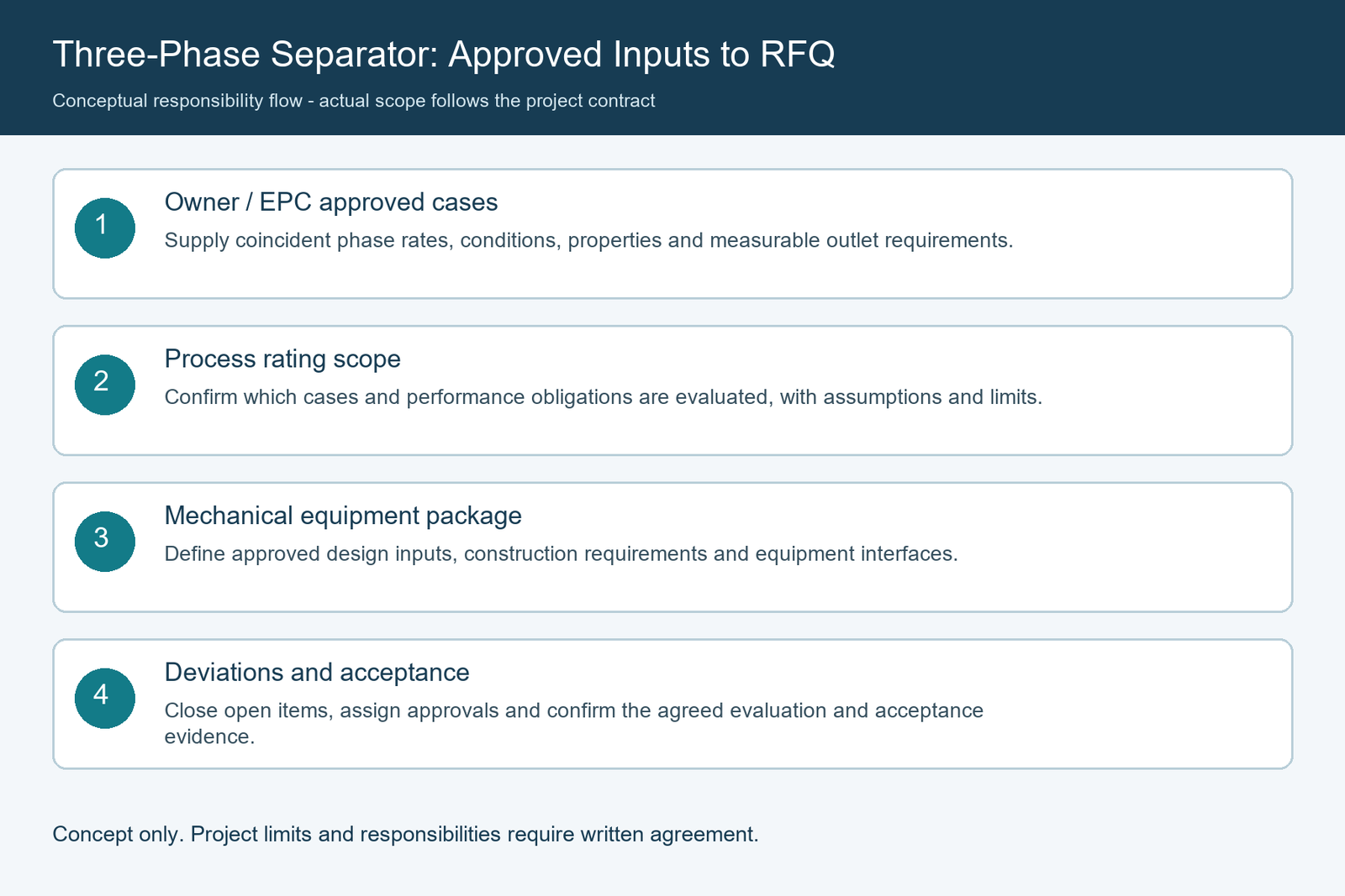
A clear handover is as important as the data itself. The project team should nominate a responsible owner for every operating case and an explicit reviewer for supplier assumptions.
| Deliverable or decision | Typical accountable party* | Required handover evidence |
|---|---|---|
| Credible operating scenarios and coincident rates | Owner/EPC process engineering | Approved process case register and datasheet revision |
| Fluid characterization and uncertainties | Owner/EPC process engineering with laboratory or specialist input as needed | Property package and documented source/assumptions |
| Outlet quality and control philosophy | Owner/EPC process, controls and downstream stakeholders | Agreed performance schedule and control narrative |
| Proposed separator process assessment | Party contracted for process design/rating | Case-by-case performance basis, assumptions and stated limits |
| Mechanical design and vessel code compliance | Responsible mechanical designer/manufacturer under contract | Approved mechanical datasheet, code basis and fabrication documents |
| Deviations and final technical acceptance | Named project approval authority | Closed clarification register and signed decision record |
Roles are illustrative and must be aligned to the actual contract. A pressure-vessel fabricator should not silently inherit responsibility for upstream multiphase-flow modeling, downstream treatment specification or field performance guarantees that are not included in its contracted scope.
For a complete custom pressure vessel, the RFQ should state whether the supplier is to provide process rating, only mechanical fabrication against an approved process design, or a wider package through named partners. Record exclusions rather than leaving them to interpretation.
What Should Buyers Submit With the RFQ?
Before issuing the inquiry, review the following items as a document-control checklist, not a one-size-fits-all engineering standard:
- Operating case register: case IDs, descriptions, duration/classification and approval status.
- Simultaneous phase rates: gas, oil and water for each case, with units, measurement basis and upstream source.
- Thermodynamic and fluid properties: coincident pressure, temperature, composition, density, viscosity and relevant emulsion/foaming assumptions.
- Required outlet conditions: gas carryover, water in oil, oil in water and applicable control or interface limits, with agreed units and test basis.
- Operating sequence: sustained low load, normal and maximum production; separately identified startup/transition and abnormal cases.
- System boundaries: upstream inlet assumptions, downstream pressures, instrument interfaces and separation-performance responsibility.
- Mechanical and procurement requirements: project code edition, design conditions, materials/corrosion inputs, inspection scope, documentation and shipping constraints.
- Open-items register: missing data, proposed assumptions, action owner, due date and approval authority.
Ask bidders to return a marked-up operating-case matrix showing covered, conditionally covered, excluded or not yet evaluated for each approved duty. This prevents a quotation based on normal flow from being mistaken for one qualified across the entire required envelope.
FAQ: Three-Phase Separator Operating Cases
Can one design case represent both turndown and peak flow?
Not reliably unless the process engineer demonstrates that it bounds all relevant gas, oil, water, property and performance combinations. A minimum and maximum total-flow figure cannot substitute for a case matrix.
Is the lowest total feed necessarily the most difficult low-flow case?
No. Gas, light-liquid and heavy-liquid rates may change independently. A low-gas/high-water or other credible combination may create different operating constraints from the minimum total rate.
Does a specified retention time guarantee oil–water separation quality?
No. Retention time is one design input. Feed dispersion, liquid properties, phase ratios, control levels and the required outlet specifications also matter. Any guarantee must have a defined operating and verification basis.
Should startup and intermittent disturbances be included in the normal turndown guarantee?
Not automatically. They should be listed and classified, with the expected duration, required performance or agreed temporary exceptions. The project authority must approve which cases belong in the contractual guarantee.
Who approves the separator operating envelope?
The owner/EPC’s designated process authority should approve the operating cases and performance requirements. Other responsibilities—process rating, mechanical design, controls and testing—must be allocated according to the project contract.
Conclusion
A useful three-phase separator specification describes credible simultaneous operating conditions, not isolated flow-rate extremes. A controlled case matrix, phase-specific properties, clear outlet-quality targets and named approval responsibilities allow EPC buyers to compare proposals without assuming that low-flow, normal-flow and peak-flow performance are automatically equivalent.
For project-based separator fabrication, provide the approved process datasheet, operating case register, fluid-property basis and technical acceptance requirements when contacting the vessel manufacturer. Unresolved process assumptions should remain visible until the responsible engineering team closes them.
References
- Bothamley, M. (2017). Quantifying Oil/Water Separation Performance in Three-Phase Separators—Part 1. Society of Petroleum Engineers, Journal of Petroleum Technology. https://jpt.spe.org/quantifying-oilwater-separation-performance-three-phase-separatorspart-1
- Bothamley, M. (2017). Quantifying Oil/Water Separation Performance in Three-Phase Separators—Part 2. Society of Petroleum Engineers, Journal of Petroleum Technology. https://jpt.spe.org/quantifying-oilwater-separation-performance-three-phase-separatorspart-2
- ASME. BPVC Section VIII, Division 1 — Rules for Construction of Pressure Vessels (official scope and edition information; the project contract governs the applicable edition). https://www.asme.org/codes-standards/find-codes-standards/bpvc-viii-1-bpvc-section-viii-rules-construction-pressure-vessels-division-1