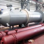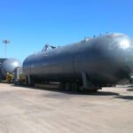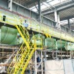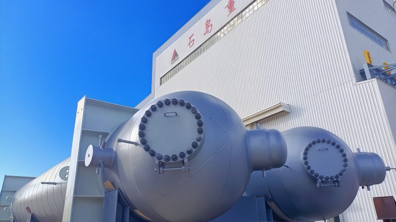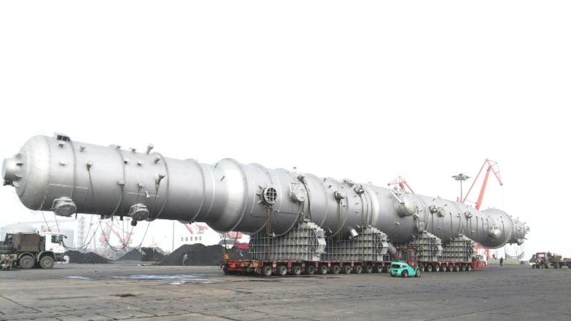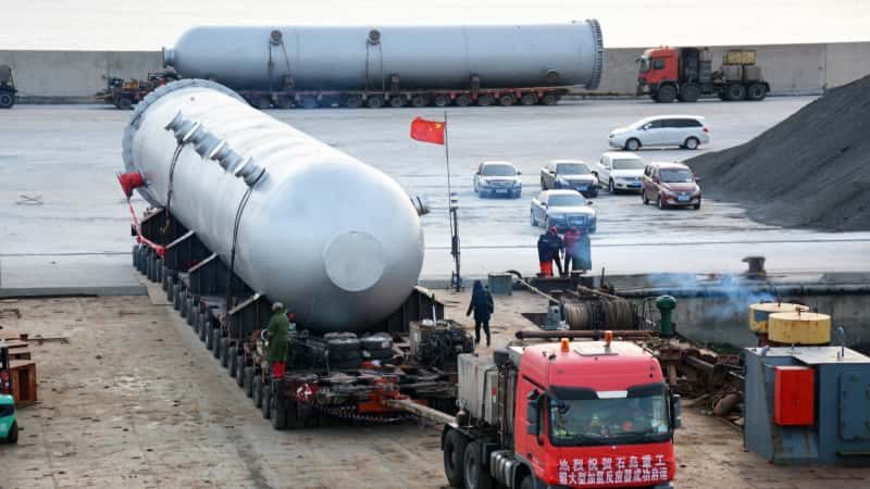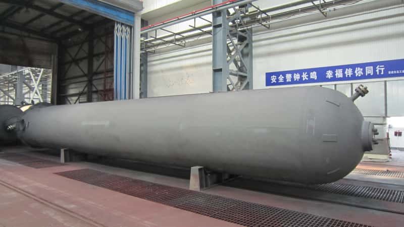

Replacing a large pressure vessel in an operating chemical or energy plant is not simply a matter of ordering a new vessel with the same capacity and nominal dimensions. Brownfield pressure vessel replacement fit-up depends on verified site geometry, existing piping and support interfaces, an achievable installation route, and an approved shutdown and change-control plan. A vessel may satisfy its mechanical design specification yet fail to fit the plant when an outdated drawing, obstructed lifting path, or unverified nozzle elevation is discovered after fabrication.
Before issuing a firm equipment RFQ, the owner and EPC team should assemble a site-verified replacement basis: the existing vessel’s identification and records; measured interfaces and obstructions; process and code requirements for the proposed vessel; transportation and installation constraints; temporary works and reinstatement boundaries; and the dates and approvals attached to each input. The manufacturer can then design and quote against a controlled set of interfaces rather than an assumed duplicate of the removed equipment.
This guide concerns complete, large custom pressure vessels—including process vessels, separators, reactors and towers—being replaced within existing facilities. It does not provide a lifting procedure, a foundation design, or permission to modify pressure-retaining components in the field.
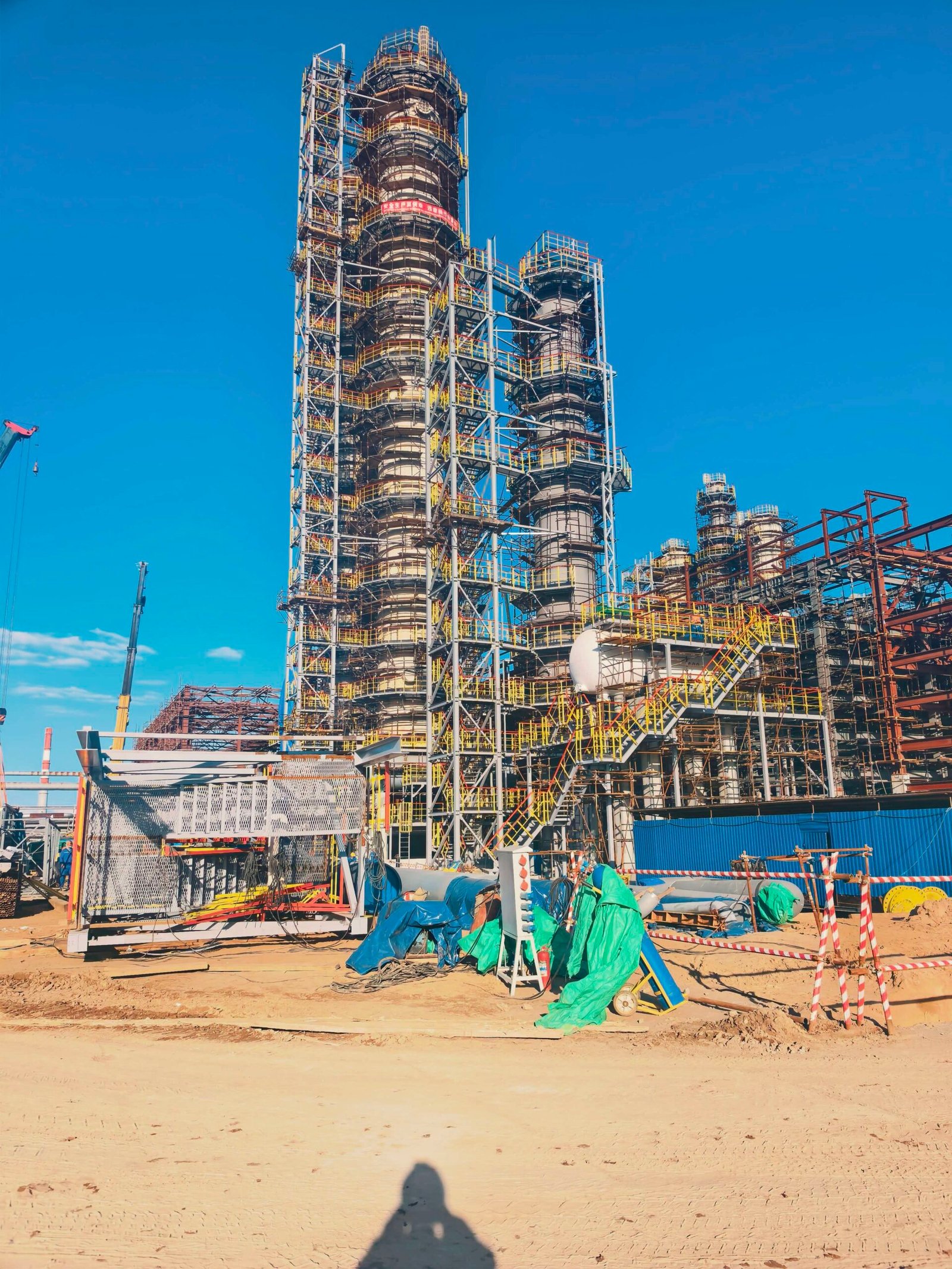
Why Is Brownfield Vessel Replacement Different From a New Installation?
A greenfield project can often coordinate equipment, piping, platforms and supporting steel around a developing layout. A brownfield replacement begins with installed assets that may have been modified, settled, repaired or obstructed since their original drawings were issued. A nominally identical vessel can therefore present different installation risks.
Three distinct questions must be answered:
- Will the new vessel perform the required duty? Confirm the current fluid, operating and design cases, material requirements, corrosion considerations and applicable construction code.
- Will it connect without unapproved alterations? Confirm the actual locations, orientations and specifications of existing nozzles, supports, flanges and adjacent piping.
- Can it be delivered, installed and maintained in the available plant? Confirm the full movement envelope, site access, removal work, lifting interfaces and shutdown constraints.
The first question belongs primarily to process and equipment engineering; the second and third require coordinated field verification. Passing one does not establish the others. For general process and code data, see the site’s pressure vessel quotation guide. The present article focuses on what makes a replacement in an existing plant different.
Establish a Reliable As-Built Basis Before Freezing the Replacement Layout
Treat legacy drawings as evidence to be checked, not as automatically correct field measurements. General arrangement drawings, P&IDs, previous vendor drawings, foundation records, inspection history and modification records may have different revision dates and may not show later site work.
Record the reference system and the credibility of each dimension
A field survey should use agreed equipment and plant datums, units, coordinate directions, elevation references and nozzle clocking conventions. Identify who performed each measurement, when it was made, what condition the plant was in, and whether access restrictions prevented direct verification. A laser scan, for example, can document visible geometry, but concealed interfaces may still require approved opening-up or later field checks. Do not present a scan as confirmation of a feature it could not observe.
Separate measured, document-derived, estimated and unresolved values. The same drawing can contain a measured vessel centerline and an unverified flange-face projection; those should not share an unquestioned “approved” status.
Reconcile installed geometry with mechanical and process records
The original nameplate, equipment dossier, thickness/corrosion records and maintenance history help identify the existing vessel. They do not by themselves confirm the condition or required code basis of the replacement. Process engineering should validate current service, including any changed operating envelope, abnormal cases and cleaning conditions. Mechanical engineering should then assess what must be redesigned rather than copied.
For covered U.S. processes, OSHA’s process safety management requirements address process safety information and management of change, with specific treatment of replacements in kind. Whether a particular project is covered, and whether a proposed replacement qualifies as in kind, must be determined by the responsible owner—not inferred from the equipment’s appearance (OSHA 29 CFR 1910.119). Outside that jurisdiction, apply the project-specific laws and management system.
What Should the Brownfield Replacement Interface Register Contain?
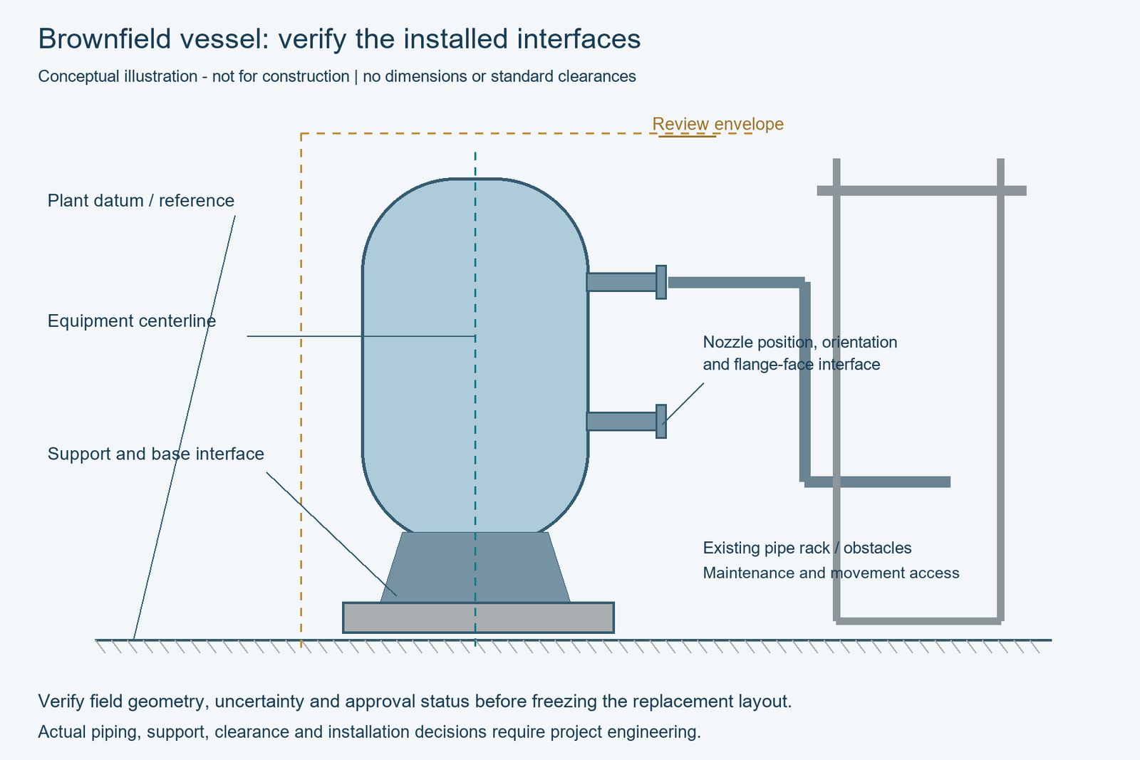
The most useful RFQ attachment is an interface register tied to evidence and approval status, not merely a single outline drawing. Each entry should identify the existing condition, proposed vessel requirement, source/revision, tolerance or uncertainty where established, verification owner and disposition of any mismatch.
| Interface or constraint | Evidence to request or verify | Question before manufacture | Typical responsible reviewer* |
|---|---|---|---|
| Equipment location | Plant coordinates, centerline, orientation, datum and surveyed elevation | Is the proposed centerline fixed and independently checked? | Owner/EPC layout |
| Overall envelope | Diameter, height/length, heads, external attachments, insulation and removal projections | What is the largest installed and movement envelope—not just shell size? | Equipment/layout |
| Process nozzles | Tag, size, pressure class, facing, material, orientation, centerline elevation and flange-face position | Will connected piping align within its engineered fit-up requirements? | Piping/equipment |
| Manways and instruments | Opening locations, access direction, instrument protrusions and valve operators | Can each item be reached, removed and operated? | Operations/maintenance |
| Existing supports | Saddle/skirt/leg geometry, anchor pattern, elevations and surveyed condition | Can the new support arrangement be accepted by civil and equipment designers? | Civil/structural/equipment |
| Piping flexibility | Adjacent piping geometry, restraints, allowable nozzle loads and construction tie-ins | Are piping loads and any proposed field changes reviewed? | Piping stress/equipment |
| Building and platforms | Steelwork, floors, overhead clearance, removable panels, handrails, cable trays | What remains in place during transit and final installation? | Site construction/layout |
| Delivery and access | Port/road/plant routes, door widths, local constraints and receiving location | Can the package physically reach its laydown and lift location? | Logistics/site construction |
| Lift and movement | Lifted configuration, mass and center of gravity basis, handling interfaces and swept path | Does a qualified lifting team have the inputs to develop and review its plan? | Lifting contractor/site |
| Turnaround boundary | Isolation strategy, removal scope, cut points, permits, outage window and reinstatement scope | Which decisions must close before the shutdown starts? | Owner/turnaround manager |
*These are coordination roles, not universally mandated contractual assignments. The project responsibility matrix must name actual approving organizations and individuals.
Illustrative uncertainty: “nozzle N3 elevation per vendor drawing” is not equivalent to “N3 elevation field verified.” If one value remains unverified, list the potential fabrication consequence and the latest date on which the EPC must resolve it. Blank fields should not silently mean “acceptable.”
Verify Nozzles, Piping and Supports as a Connected System
A matching nozzle diameter does not prove fit-up. Connection alignment also depends on centerline coordinates, flange face, rating, bolt orientation, neck projection, orientation and the actual position of adjoining piping. Hot and cold operating conditions, support movement and piping flexibility can add engineering considerations beyond a static dimensional check.
For each critical tie-in, identify which side of the connection is fixed, whether a spool can be replaced, and who is responsible for assessing piping stresses and permissible nozzle loads. If a proposed design requires cutting, rotating or replacing site piping, treat that as a defined engineering change and construction scope—not an informal adjustment available to the installation crew. The applicable piping code and project specifications must be confirmed by the piping engineer; ASME B31.3 is one example of a process-piping framework, not an automatic rule for every plant.
Support compatibility deserves the same discipline. A skirt-base bolt pattern may appear to match while the base elevation, bearing condition, weight distribution or load cases have changed. Request the new vessel’s relevant weight states and support-interface loads for civil review, and separately establish whether the existing structure has been checked for the revised design. The vessel weights and foundation-load handover guide deals with load reporting in detail; this article does not calculate foundation or anchor capacity.
Where the old vessel’s material has degraded or the process service has changed, a like-for-like geometry should not be mistaken for a complete technical justification. Materials, corrosion allowance, inspection requirements, relief connections and design conditions remain subject to the applicable engineering review.
Check the Full Removal, Delivery and Installation Envelope
The movement envelope is often larger than the finished vessel’s nominal dimensions. Temporary shipping saddles, lifting attachments, protruding nozzles, insulation components supplied separately, lifting orientation and turning or tilting movements can all affect the space needed.
Before committing to an integral shop-fabricated configuration, the project team should review at least three states: outgoing equipment during removal, incoming equipment as transported and handled, and the replacement in its permanent installed condition. Include any temporary removal or reinstatement of nearby pipe spools, platforms, handrails, structural members or cables. These activities require their own approved construction and safety controls.
A route review should consider external transportation restrictions and the internal plant path from receiving point to laydown and final position. In some cases the limiting feature is not a highway bridge but a pipe rack or narrow operating-unit opening. Do not invent universal clearances: establish project-specific allowances with the transport and lifting designers.
A qualified contractor must determine crane selection, load handling, lifting geometry and ground support. For U.S. construction work where it applies, OSHA 29 CFR 1926.1402 addresses crane ground conditions and information on known subsurface hazards. This is cited to identify an interface responsibility, not as a substitute for a lift plan or local legal review.
Define Shutdown, Temporary Work and Reinstatement Boundaries
Replacement can be mechanically feasible yet impossible within the planned turnaround if enabling work is not identified. The RFQ and project execution basis should clarify which preparatory activities are permitted while the plant is operating, what must wait for isolation, and which interfaces cannot be opened or disturbed until the owner authorizes the work.
Record the planned outage window and important dependencies without treating a preliminary schedule as guaranteed. Relevant items may include isolation and decontamination responsibilities; removal of the existing vessel; temporary structural work; any approved piping modifications; installation and connection inspections; reinstatement of platforms, insulation and instruments; and post-installation testing and return-to-service checks. The owner, EPC, site contractor and equipment supplier should agree on exactly which deliverables are in each party’s scope.
Distinguish supply from site services. A vessel manufacturer’s quotation may cover engineering, fabrication, shop inspection, preservation and delivery while excluding site measurement, craneage, removal, field welding or commissioning. Do not assume those services are included. State explicit inclusions, exclusions, required site data, and points at which another party must approve a handover.
Where a covered process is subject to OSHA PSM, the owner should determine applicable management-of-change and pre-startup safety review obligations. OSHA’s pre-startup provision is conditional; it is not a universal rule that every equipment exchange triggers the same review or that the manufacturer owns the owner’s safety-management duties.
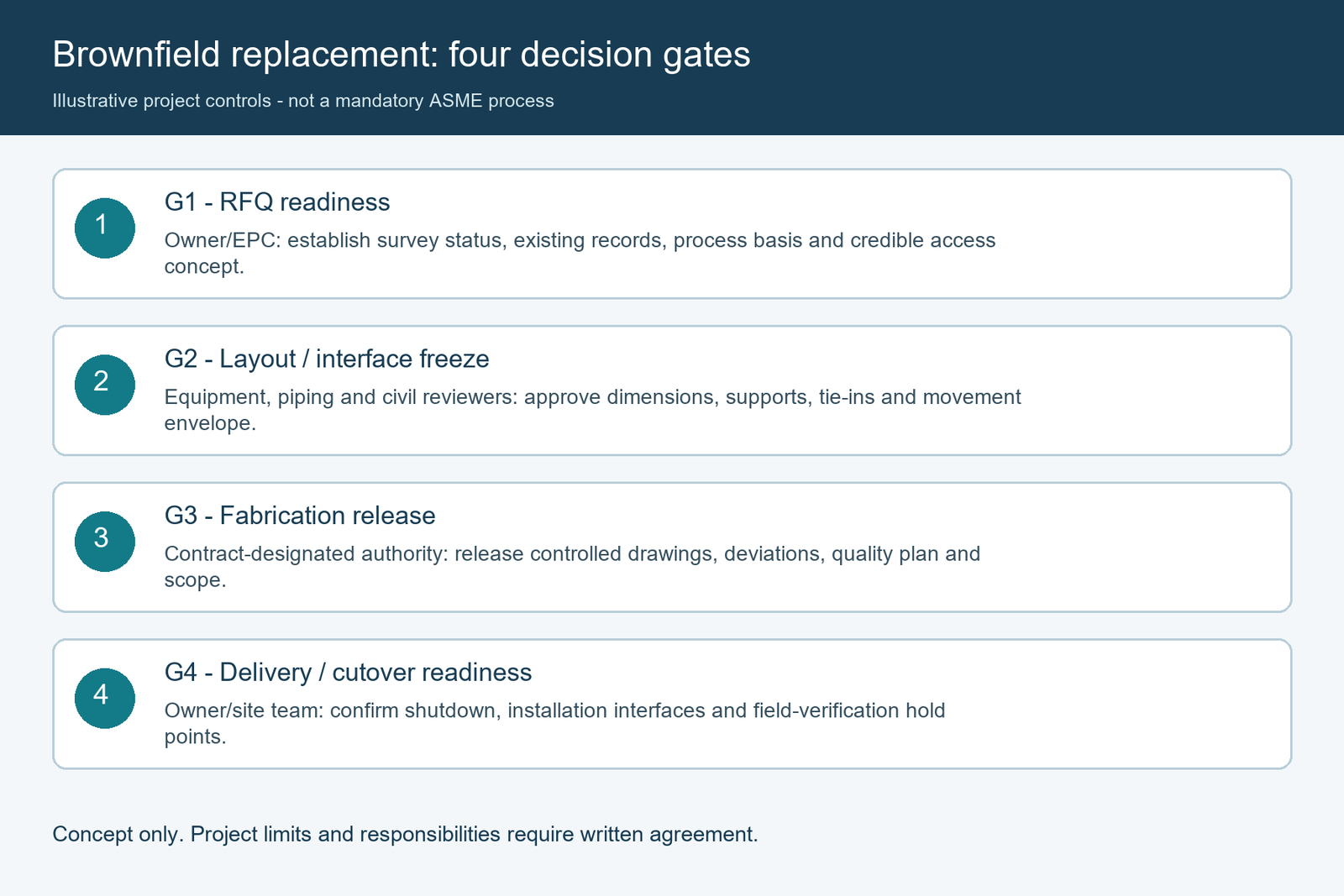
Use Four Decision Gates to Prevent Late Fit-Up Changes
A practical brownfield workflow separates preliminary quotation from authorization to fabricate. These gates are proposed project controls, not a mandatory sequence prescribed by ASME or any universally applicable standard.
| Project gate | Evidence needed to pass | Typical unresolved issues that block release |
|---|---|---|
| G1 — RFQ readiness | Site survey status, existing records, process basis, preliminary interface register and delivery concept | Unknown tie-in locations or no credible access route |
| G2 — Layout/interface freeze | Approved dimensions, nozzle and support schedules, coordinated piping/civil review, installation-envelope assessment | Conflicting datums, disputed support location or unreviewed piping changes |
| G3 — Fabrication release | Revision-controlled vessel drawings, approved technical deviations, required quality plan, manufacture scope and handling assumptions | Open dimension that would change a pressure-boundary feature or support detail |
| G4 — Delivery/cutover readiness | Confirmed logistics/installation interfaces, owner-authorized shutdown preparation, approved change dispositions and defined field-verification hold points | Unresolved temporary removal scope, access restrictions or absent site acceptance authority |
The approval level needed at each gate depends on the contract and project risk. An early budgetary quotation can proceed with labelled assumptions; a fabrication release should not rely on hidden guesses about a critical tie-in. A supplier’s “drawing reviewed” stamp must not be silently interpreted as approval of a site condition beyond the reviewer’s scope.
Manage changes against the interface baseline
Give each interface a unique ID and retain its source file, revision, survey status, approving role and date. When site work exposes a different condition, log the discrepancy and its impact on drawings, piping, supports, transport configuration and turnaround schedule. Reissue affected information through the agreed document and change process before manufacturing or field work depends on it.
Avoid a simplistic “the new vessel is the same size, so no change review is needed” conclusion. Geometric similarity does not prove equivalent process design, nozzle loads, materials or site safety implications.
What Should Buyers Send the Manufacturer With the RFQ?
A credible initial package should combine the normal vessel process/design datasheet with a brownfield replacement appendix. Provide what is available, clearly distinguishing approved values from preliminary data:
- Existing equipment tag, location, intended replacement duty and the governing project codes/specifications.
- Available nameplate, drawings, P&IDs, modification history and condition information, with revision and reliability status.
- Surveyed plant datums, nozzle/interface register, obstruction map and maintenance/access envelope.
- Existing support information and the required civil/piping review interfaces.
- Transportation, laydown, lifting and installation-route restrictions, with site-contractor responsibilities identified.
- Planned turnaround window, temporary work/removal/reinstatement scope and site test or inspection interfaces.
- Register of assumptions, uncertainties, deviations, decision owners and deadlines.
Ask the supplier to respond against these exact interfaces: identify confirmed matches, proposed changes, data still required, and any exclusions. The purchaser and its appointed engineers remain responsible for approving site data and integration decisions; the manufacturer should not be represented as certifying unmeasured existing conditions.
For the scope of a complete large vessel, review the manufacturer’s custom pressure-vessel products and submit the existing-equipment and site-interface information with the enquiry. Feasibility, dimensions, code compliance and services are project-specific and require technical confirmation.
Frequently Asked Questions
Can an old vessel drawing be used as the final replacement layout?
Only when the responsible project team has verified that the relevant dimensions and interfaces still represent the installed plant. An older drawing can start the survey, but unconfirmed locations and modifications should remain flagged until reconciled.
Is matching the existing nozzle size enough to guarantee fit-up?
No. Flange specifications, positions, elevations, orientations, projections, connected piping conditions and allowable loading can all matter. The piping and equipment designers must approve the relevant interfaces.
Should a replacement be designed using the old vessel’s original code edition?
Not automatically. The contract, jurisdiction, equipment classification and current project engineering basis determine the applicable requirements. The original record is useful evidence, but neither the old edition nor a later edition should be assumed without review.
Can a manufacturer guarantee that a vessel will fit without a field survey?
A supplier can identify proposed dimensions and documented assumptions, but a project-specific fit guarantee requires an agreed, reliable site-interface basis and clearly allocated responsibility. Unknown field conditions cannot be converted into verified inputs by quotation wording alone.
Does a like-for-like replacement always avoid management of change?
No universal conclusion applies. In a U.S. facility subject to OSHA PSM, replacements in kind are treated distinctly under the regulation, but the owner must determine whether the actual change qualifies. Other sites follow their own applicable rules and approved change-control procedures.
References
- ASME — BPVC Section VIII, Division 1 — official construction-code scope. The project contract and jurisdiction determine the applicable edition.
- OSHA — 29 CFR 1910.119, Process Safety Management — process safety information, mechanical integrity, management of change and conditional pre-startup safety review for covered U.S. processes.
- OSHA — 29 CFR 1926.1402, Ground Conditions — crane ground-condition responsibilities where U.S. construction requirements apply.
- ASME — B31.3, Process Piping — official description of a process-piping code; applicable edition and scope must be specified by the project.
- API — API 510 Pressure Vessel Inspection Code — in-service inspection, rating, repair and alteration context for applicable equipment; not a replacement-vessel dimensional-fit standard.