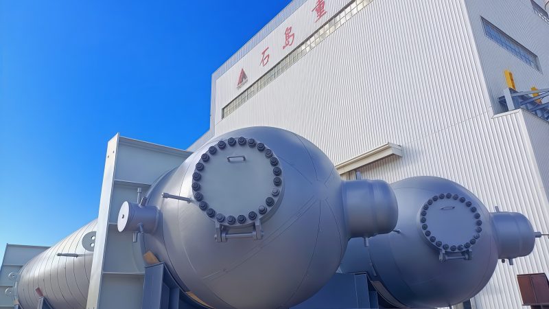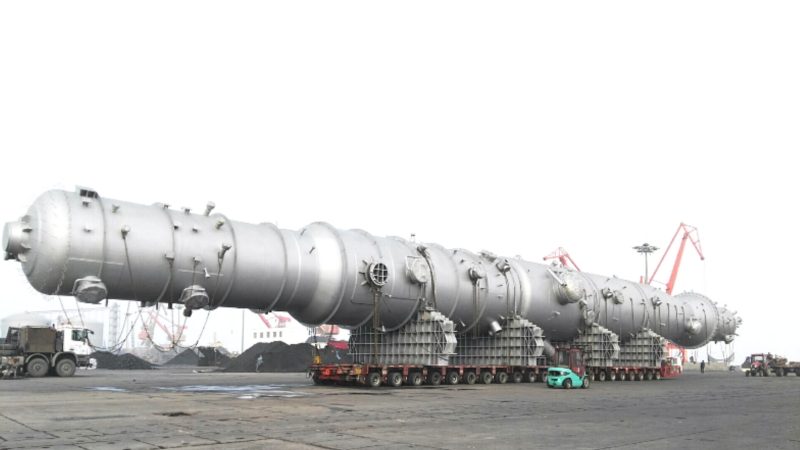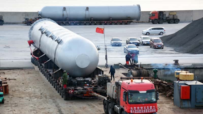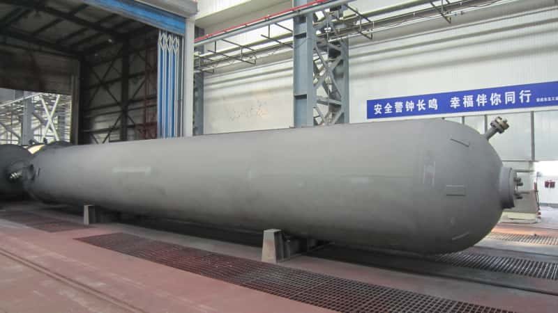

For EPC buyers, factory acceptance testing is not simply a final visit to witness pressure testing. It is the point at which manufacturing evidence, physical equipment identification, inspection findings, and unresolved technical matters must be reconciled before the agreed release.
EPC buyers should review the approved Inspection and Test Plan, verify that material certificates correspond to the actual fabricated components, examine PMI results within the limits of the selected method, and confirm that welding, examination, pressure testing, dimensional checks, and final documents meet the applicable project requirements. Material certificates, traceability records, and PMI provide different evidence and must be reviewed together.
A material test certificate records specified inspection and test results; component identification connects the physical material to those records; and PMI provides additional chemical verification where required. Understanding these distinctions helps buyers identify evidence gaps before they become acceptance or shipment problems.
What Should the ITP Establish Before Factory Acceptance Testing?
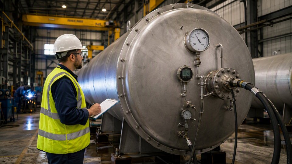
Factory acceptance testing should begin with an agreed inspection scope, not a checklist created immediately before shipment. For a large pressure vessel or shell-and-tube heat exchanger, the Inspection and Test Plan (ITP) should connect the purchase order, approved design documents, applicable construction code, and project-specific inspection requirements.
An effective ITP identifies the activity, reference documents, acceptance criteria, responsible parties, required records, and inspection intervention point. This helps the EPC buyer distinguish a satisfactory manufacturing result from a result that has not yet been adequately demonstrated.
Hold, Witness, and Review Points
Inspection activities commonly use Hold (H), Witness (W), and Review (R) designations, although exact definitions and notification requirements depend on the agreed project procedure.
- Hold point: Work cannot pass the designated stage until the required release or disposition has been obtained under the approved ITP.
- Witness point: The designated party is notified and has the opportunity to observe the activity. The procedure determines how nonattendance is handled.
- Review point: Required records are submitted for examination and acceptance as applicable.
An activity is not automatically a purchaser hold point simply because it involves pressure testing, radiography, material verification, or nameplate inspection. Its status must be established by the governing requirements and approved inspection arrangements.
Check the Applicable Document Baseline
Before accepting the ITP, buyers should confirm that it refers to the correct equipment tag, document revisions, design code and edition, material specifications, and examination requirements.
For equipment constructed under ASME BPVC Section VIII, the applicable division and contractually adopted edition should be identified. ASME’s official description of Section VIII Division 1 covers design, fabrication, inspection, testing, and certification; it is not a substitute for consulting the actual governing provisions. (ASME BPVC VIII.1)
The ITP should also identify when material verification occurs. Certificates and physical material identity should be reviewed while relevant components remain identifiable, rather than leaving all discrepancies to the final FAT meeting.
What Do Mill Certificates and Material Traceability Records Demonstrate?
A mill test certificate provides documented test results for material supplied under a specified material standard and inspection arrangement. It does not, by itself, prove that the same material was installed in a particular pressure vessel.
For EPC buyers, material verification involves two connected checks: whether the certificate supports the specified material requirements, and whether the manufactured component can be traced to the material represented by that certificate.
Review the Certificate Against the Material Specification
Depending on the applicable material standard, inspection requirements, and certificate type, a mill test certificate (MTC), mill test report (MTR), or equivalent inspection document may report:
- Material specification and grade.
- Product form and dimensions.
- Heat, cast, batch, or other identification number.
- Recorded chemical analysis.
- Tensile or other required mechanical test results.
- Impact testing or supplementary test results, where required.
- Material condition or heat-treatment information, where specified.
- Identification of the issuing organization and authorized validation.
The presence of these fields does not establish compliance automatically. The reviewer must compare the recorded results and material identity against the specification, purchase requirements, and applicable acceptance criteria.
Some required evidence may appear in properly linked supplementary test records. A result should not be rejected solely because it is outside the main certificate; its acceptability depends on the required document format, validity, and traceability.
EN 10204 Type 3.1 and Type 3.2: What Changes?
Where the purchase specification adopts EN 10204, the certificate type affects the inspection and validation arrangement.
| Document | Main distinction | Buyer review |
|---|---|---|
| EN 10204 Type 3.1 | Specific inspection results validated by the manufacturer’s authorized inspection representative, independent of the manufacturing department | Check the specified product, recorded results, identification, and appropriate validation |
| EN 10204 Type 3.2 | Specific inspection results with the additional validation arrangements involving the purchaser’s authorized representative or the inspector designated by official regulations | Verify the required independent involvement and documentation |
This distinction is consistent with the public explanation provided by RINA on EN 10204 Type 3.2.
Type 3.2 is not automatically mandatory for every industrial pressure vessel, and a certificate’s designation does not eliminate the need to check actual material conformity.
Connect the Certificate to the Fabricated Component
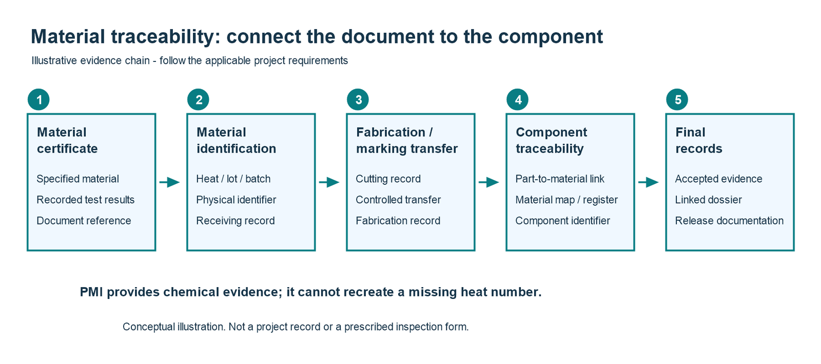
Material traceability should allow a reviewer to follow an identifiable pressure-retaining component back to its applicable material documentation.
That chain may involve receiving records, identification markings, approved marking-transfer procedures, cutting records, material maps, and fabrication travelers.
| Evidence | Question the buyer should answer |
|---|---|
| Material certificate | Which material and tests does this document represent? |
| Original identification | Which heat, lot, or other traceable identifier applies to the incoming material? |
| Cutting or fabrication record | How was identification maintained after the material was divided or processed? |
| Component traceability register | Which material identity is assigned to this shell course, head, nozzle, flange, or other relevant part? |
| Final manufacturing record | Can the finished component be linked to its accepted material evidence? |
Editorial traceability review template; not a prescribed ASME form.
Not every component must carry an identical permanent marking throughout fabrication. The essential requirement is an identification and record-control method consistent with the applicable material, manufacturing, and project requirements.
If physical identification is lost, a matching chemical analysis cannot automatically recreate the original heat number. The affected material requires controlled investigation and an approved disposition; additional testing may assist the review but cannot invent a missing manufacturing history.
What Can PMI Verify—and What Cannot It Prove?
Positive material identification (PMI) helps verify the chemical identity of metallic materials or components. It is particularly useful for checking whether the selected alloying elements are consistent with the specified material grade.
However, PMI does not replace a material certificate, establish heat-number traceability, or demonstrate all the properties required for pressure vessel construction.
XRF Versus OES: Choose the Method by the Required Elements
X-ray fluorescence (XRF) and optical emission spectroscopy (OES) can both support alloy verification, but their analytical capabilities are different.
| Review factor | Handheld XRF | Spark OES |
|---|---|---|
| Typical purpose | Identification of many alloy grades through detectable elemental composition | Quantitative alloy analysis, including selected light elements |
| Commonly relevant elements | Chromium, nickel, molybdenum, and other detectable alloying elements | Alloying elements plus carbon and certain other light elements, subject to instrument capability |
| Carbon verification | Conventional handheld XRF cannot measure carbon | Suitable OES equipment and methods can measure carbon |
| Surface considerations | Coatings, contamination, geometry, and surface condition may affect results | Requires appropriate surface preparation and may leave a localized spark mark |
| Procurement limitation | A displayed alloy grade does not establish all material requirements | An OES result still does not establish mechanical properties, heat-treatment history, or original material identity |
Method comparison based on publicly available ASTM guidance and instrument-manufacturer technical information. Actual detection limits, accuracy, and applicable procedures must be confirmed for the equipment used.
For instance, a handheld XRF result may support the identification of an alloy consistent with Type 316 stainless steel through its detectable alloying elements. It cannot, by itself, verify the carbon content needed to distinguish 316 from 316L.
Thermo Fisher’s comparison of XRF, LIBS, and OES explains this limitation. Hitachi High-Tech’s PMI inspection guidance separately identifies carbon analysis as a reason to select a suitable OES method.
For duplex stainless steel, if nitrogen is a required verification element, buyers should similarly confirm whether the proposed analytical method and instrument can measure it adequately. A general alloy-grade display is not sufficient evidence for an element the equipment does not analyze.
A Matching Alloy Grade Is Not Full Material Compliance
Material verification should distinguish the following evidence:
- Chemical identity: Whether the detected elements are consistent with the specified alloy requirements within the method’s applicable capability.
- Mechanical properties: Whether required tensile, yield, elongation, and other mechanical test results are supported by appropriate material or supplementary test records.
- Toughness requirements: Whether applicable impact test conditions and results are documented.
- Material condition: Whether required heat-treatment or supply-condition evidence is available.
- Traceability: Whether the tested component is linked to the relevant material identity and records.
A PMI reading cannot establish a material’s yield strength, prove that a specified heat-treatment cycle occurred, or demonstrate that a required Charpy impact test was passed.
The test method must match the question being asked. ASTM E1476-04(2022), Standard Guide for Metals Identification, Grade Verification, and Sorting, identifies different available methods and explains their roles in metal identification and quality assurance. Its public description does not make a single method universally sufficient for complete material certification.
For the EPC buyer, a PMI report is therefore supporting evidence within the overall material verification package, not a replacement for the package itself.
How Should Buyers Define PMI Scope and Resolve Discrepancies?
The PMI scope should be established by the applicable material verification requirements, service conditions, component specifications, and approved project ITP.
A statement such as “100% PMI required” or “random PMI sufficient” is incomplete unless the document defines the materials, components, sampling basis, test method, acceptance criteria, and responsible parties.
Define Coverage Before Testing
The approved material verification plan should identify:
- Material scope: Which alloy families, grades, or specified materials require PMI.
- Component scope: Which parts of the complete pressure vessel or heat exchanger are included.
- Sampling extent: Whether verification is required for every defined item or a specified selection, and how that selection is made.
- Test location: Where measurements are taken, including any relevant requirements for weld deposits, overlays, or accessible component surfaces.
- Method: Which analytical technique is appropriate for the required elements and acceptance basis.
- Reporting: Which results, component identifiers, instrument or procedure references, and dispositions must be retained.
These items are an editorial purchasing checklist. They do not establish a mandatory industry-wide inspection percentage.
Depending on project requirements, the scope may include pressure-retaining base materials, corrosion-resistant alloy components, weld metal, or other specified parts. A purchaser should not assume the same coverage for every material or service simply because the equipment is described as a pressure vessel.
API RP 578 is an established reference for material verification programs, but buyers need to confirm the applicable edition, scope, and incorporation into their contract. An API reference alone does not automatically establish a universal inspection percentage for every vessel component. The API standards catalog provides the official publication listing.
Confirm Surface and Record Conditions
A PMI result is meaningful only when the test is suitable for the material surface and the required elements.
Coatings, scale, contamination, surface geometry, or an unsuitable measurement location may compromise the usefulness of a result. Appropriate preparation and verification procedures should be defined according to the selected method.
Hitachi High-Tech’s PMI testing guidance emphasizes the importance of surface preparation, suitable measurement conditions, instrument checks, and recording the analysis.
For document review, request records that identify the tested part, location, material requirement, measured or reported elements, method, applicable acceptance basis, and final disposition. Additional record fields should follow the project procedure.
Close Mismatches Through a Controlled Disposition
Consider an illustrative situation: a shell nozzle is documented as a specified stainless steel grade, but the PMI result does not match the expected alloy identification.
The buyer should not accept a verbal explanation that the result is “close enough.” Equally, the first unexpected reading does not automatically establish that the entire vessel must be rejected.
The responsible parties should follow a controlled sequence:
- Identify the affected component and prevent unintended acceptance or use while the discrepancy is unresolved.
- Verify the component identity, certificate references, test location, instrument suitability, and surface condition.
- Perform additional verification or testing when required by the approved procedure.
- Have the responsible engineering and quality authorities assess the evidence against the actual specification.
- Record the conclusion, approved corrective action or other disposition, and closure evidence.
If traceability is genuinely broken, a satisfactory PMI result cannot simply be assigned to an unknown heat number. Additional evidence or an approved engineering disposition is needed, and material rejection or replacement may be necessary.
The supplier normally provides the affected material records, investigation findings, and proposed corrective action within its agreed scope. The purchaser’s or EPC’s responsible technical representative reviews the proposed disposition, with independent or authorized inspection involvement wherever required.
For the broader handling of departures from a purchase specification, see how EPC buyers compare technical deviations in pressure vessel quotations.
How Do Welding, Pressure Testing and Dimensional Checks Fit Into FAT?
Material verification is one part of factory acceptance. After the required materials and identities have been reviewed, the EPC buyer must also confirm that fabrication, inspection, testing, and dimensional evidence support the completed equipment under the applicable construction and purchase requirements.
The scope and sequence of these activities should follow the approved ITP rather than an assumed universal inspection order.
Welding, NDE, and Heat-Treatment Records
For welded pressure equipment, the review may include approved welding procedures, procedure qualification records, welder or welding-operator qualifications, weld maps, examination reports, repair records, and any required heat-treatment documentation.
The buyer should check that the relevant records correspond to the actual equipment and approved fabrication revisions.
Nondestructive examination methods such as radiographic testing, ultrasonic testing, magnetic particle testing, and liquid penetrant testing have different applications. The selected technique, examination extent, personnel qualifications, and acceptance criteria must follow the applicable construction rules and project requirements.
Where post-weld heat treatment is required, the documentation should demonstrate that the specified procedure was carried out and that relevant monitoring records are traceable to the treated component or weld.
A PMI result does not replace weld examination, and an NDE report does not establish the chemical identity of the base material.
Pressure Testing: Verify the Approved Basis, Not a Generic Multiplier
The pressure-test review should confirm:
- The applicable design and test code, including edition and division.
- The approved test pressure and its supporting calculation or governing basis.
- Test medium and relevant compatibility or cleanliness requirements.
- Any precautions required by material condition, metal temperature, or test method.
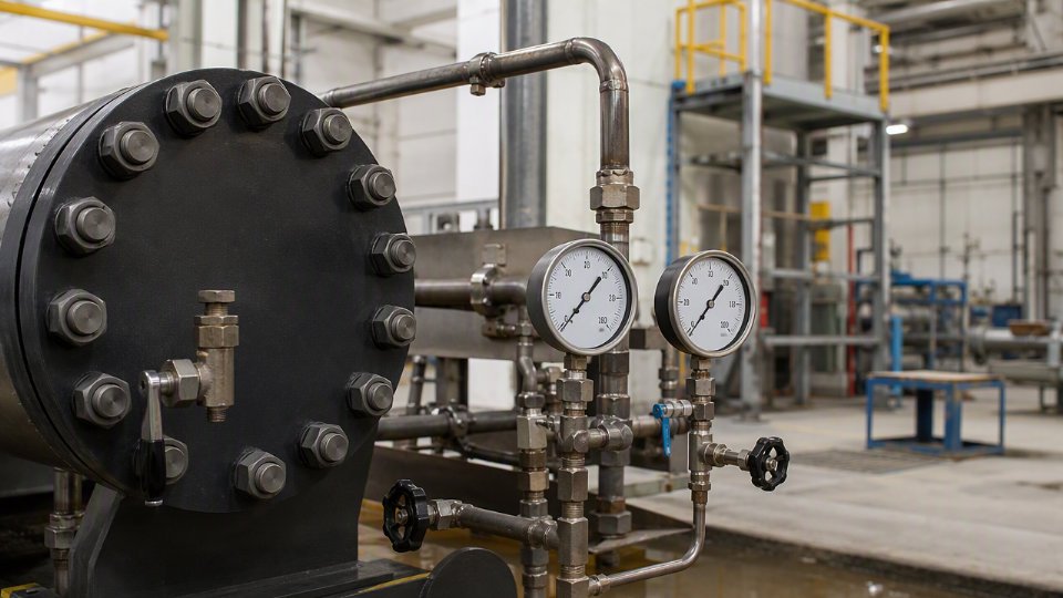
- Instrument identification and applicable calibration evidence.
- The approved procedure, observed results, and final test record.
- Required inspection participation and disposition of any abnormal result.
Do not assume that every pressure vessel or shell-and-tube heat exchanger uses an identical test-pressure multiplier. Different code provisions, allowable-stress considerations, component arrangements, and project specifications may affect the required basis.
Where pneumatic testing is proposed, the applicable rules, approval requirements, and additional safety evaluation must be established before the procedure is accepted. A purchaser should not replace a qualified project procedure with generic pressurization instructions.
For a shell-and-tube heat exchanger, buyers should also identify the relevant shell-side and tube-side test arrangements, pressure boundaries, and differential-pressure limitations. The accepted sequence depends on the particular design and specified testing scope.
ASME’s Section VIII Division 1 overview confirms that inspection and testing fall within the construction standard’s scope; the project must still apply the actual adopted requirements.
Dimensional and Interface Verification
The final physical inspection should compare the manufactured equipment with its approved drawings and agreed tolerances.
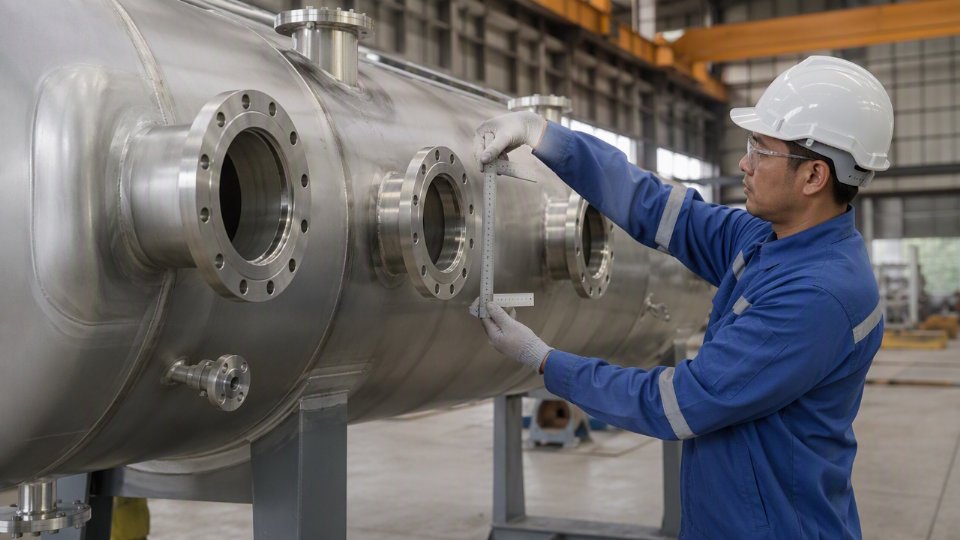
Important checks may include overall dimensions, supports, nozzle positions, flange interfaces, equipment identification, lifting or transportation provisions, and features relevant to installation.
For a complete shell-and-tube heat exchanger, inspection should consider the interfaces that are part of the contracted equipment. Additional skid or auxiliary-system inspections apply only when those items are included in the actual supply scope.
A dimensional difference should be assessed against the approved design and tolerance requirements, not an invented universal millimeter allowance.
What Must Be Closed Before Equipment Release?
The final equipment release should be based on both the physical inspection results and the agreed manufacturing records. A pressure test pass, a satisfactory PMI report, or an approved certificate alone does not establish that every contractual requirement has been completed.
The EPC buyer should reconcile the approved ITP, inspection status, material verification findings, and final manufacturing dossier before authorizing shipment under the applicable release procedure.
Review the Final Evidence Package
The required manufacturing records depend on the equipment and contract. A release review may cover:
| Record group | Main question |
|---|---|
| Approved equipment documents | Do the applicable drawings and technical specifications match the manufactured configuration? |
| Material verification | Are certificates, component identities, traceability records, and required PMI findings reconciled? |
| Welding and examination | Are the required welding qualifications, examination results, and repair records complete? |
| Heat treatment | Are required treatment and monitoring records available and accepted? |
| Pressure testing | Does the documented result correspond to the agreed procedure and equipment boundary? |
| Dimensional and final inspection | Are recorded measurements and physical interfaces acceptable? |
| Deviations and nonconformances | Have all release-blocking items received authorized dispositions? |
| Final release documents | Are the applicable manufacturer, purchaser, inspector, and regulatory approvals complete? |
Editorial equipment-release review template; final deliverables follow the contract and applicable construction requirements.
Where equipment certification or Authorized Inspector involvement is required, the buyer should verify the relevant documentation and sign-offs using the applicable rules. The same documentation arrangement must not automatically be assumed for every jurisdiction or vessel type.
Distinguish Closed Issues From Conditional Actions
An unresolved material discrepancy should not be hidden inside an otherwise complete data book.
Any outstanding action should identify the affected equipment, requirement, responsible party, technical disposition, and agreed completion condition.
If the contract permits conditional release for an item, that permission should be recorded explicitly. Mandatory regulatory, code, or safety requirements cannot be waived merely by commercial agreement.
The final review should be able to answer a practical question:
Can the purchaser trace the pressure-retaining materials and required inspection evidence to the actual equipment being released?
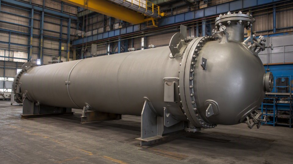
For a complete shell-and-tube heat exchanger or other custom pressure vessel, the material verification scope should be defined together with the equipment specification, inspection plan, and required final documentation—not inferred from a generic promise of full compliance.
Frequently Asked Questions
Is 100% PMI mandatory for every pressure vessel?
No. The required extent depends on the governing documents, material, service, component scope, and approved inspection plan. Where complete verification of defined components is required, those items must be identified explicitly. No universal percentage should be inferred from the term “pressure vessel” alone.
What if the required element cannot be measured by the proposed PMI method?
The responsible technical team should select a method capable of verifying the relevant element, or establish another acceptable verification route under the applicable specification. For example, conventional handheld XRF cannot determine carbon content. If carbon measurement is required, a suitable alternative analytical method and its limitations must be assessed.
Can electronic mill certificates be accepted instead of paper originals?
Electronic documents may be acceptable under the project’s documentation requirements, provided authenticity, validation, integrity, identification, and traceability can be established. The required certificate type and permitted document format should be agreed before procurement. A scanned certificate with an unreadable heat number or missing required validation is not acceptable merely because a file was submitted.
Conclusion
A reliable FAT review connects the physical pressure vessel to the evidence supporting its manufacture. Mill certificates, component identification, PMI records, examination results, and final approvals each answer different questions; none should be used as a blanket substitute for the others.
For a custom industrial pressure vessel or heat exchanger enquiry, provide the material specifications, equipment datasheets, inspection requirements, and expected manufacturing record deliverables. These establish a clearer basis for agreeing material verification and factory acceptance documentation before fabrication begins.
References
- ASTM International. ASTM E1476-04(2022): Standard Guide for Metals Identification, Grade Verification, and Sorting. Official public overview. https://store.astm.org/e1476-04r22.html
- RINA. EN 10204 Type 3.2 Certification for Metallic Materials. Official public explanation of inspection certificate validation. https://www.rina.org/en/material-and-product-certification
- Hitachi High-Tech Analytical Science. Positive Material Identification (PMI) Inspection. Manufacturer’s technical application information. https://hha.hitachi-hightech.com/en/product-range/applications/pmi-inspection
- Thermo Fisher Scientific. PMI Technologies: What’s the Difference Between XRF, LIBS, and OES? Manufacturer’s technical overview. https://www.thermofisher.com/blog/metals/pmi-technologies-whats-the-difference-between-xrf-libs-and-oes/
- Hitachi High-Tech Analytical Science. (2018). The Do’s and Don’ts of Positive Material Identification (PMI). https://hha.hitachi-hightech.com/en/blogs-events/blogs/2018/07/26/the-dos-and-donts-of-pmi/
- American Petroleum Institute. API Standards Digital Catalog, including the listing for API RP 578. https://www.api.org/products-and-services/standards/digital-catalog
- ASME. BPVC.VIII.1 — Rules for Construction of Pressure Vessels, Division 1. Official scope and edition information. https://www.asme.org/codes-standards/find-codes-standards/bpvc-viii-1-bpvc-section-viii-rules-construction-pressure-vessels-division-1