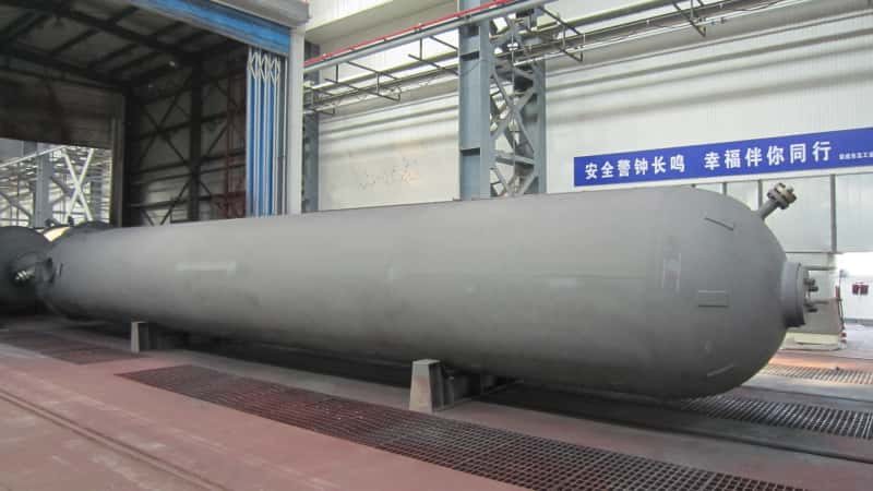

Fertilizer plant expansions stall — not at the reactor or the granulation line — but at the ammonia receiving and storage interface. When storage capacity lags behind increased synthesis throughput, operators are forced into shorter inventory cycles, more frequent rail-car or pipeline deliveries, and the kind of rushed transfer operations that drive valve seat erosion, pump cavitation events, and relief valve chatter. Each unplanned shutdown to deal with a leaking vapor-return line or a tripped transfer pump can cost a mid-size urea plant anywhere from tens of thousands to over a hundred thousand dollars per day in lost production, depending on nameplate capacity and prevailing urea prices.
Liquid ammonia storage and transfer equipment for a fertilizer plant expansion typically centers on horizontal or spherical pressure vessels ranging from 50 m³ to 3,000 m³, designed for operating pressures of 1.6 MPa to 2.5 MPa at ambient temperature, fabricated from Q345R or SA-516 Gr.70 plate at wall thicknesses of 16 mm to 40 mm depending on vessel diameter and design code, paired with centrifugal or reciprocating transfer pumps sized for 10 m³/h to 200 m³/h with a minimum vapor-pressure margin of 0.15 MPa above NPSH to prevent cavitation.
What separates an expansion that comes online on schedule from one that bleeds cost overruns is usually the sequence of decisions made at the equipment specification stage — long before the first weld is laid. The material grade, the design code jurisdiction, the pump configuration, and the vapor-return system architecture each carry downstream consequences that are nearly impossible to reverse once fabrication is underway. The sections that follow work through those decisions in the order an engineer or procurement manager actually encounters them.
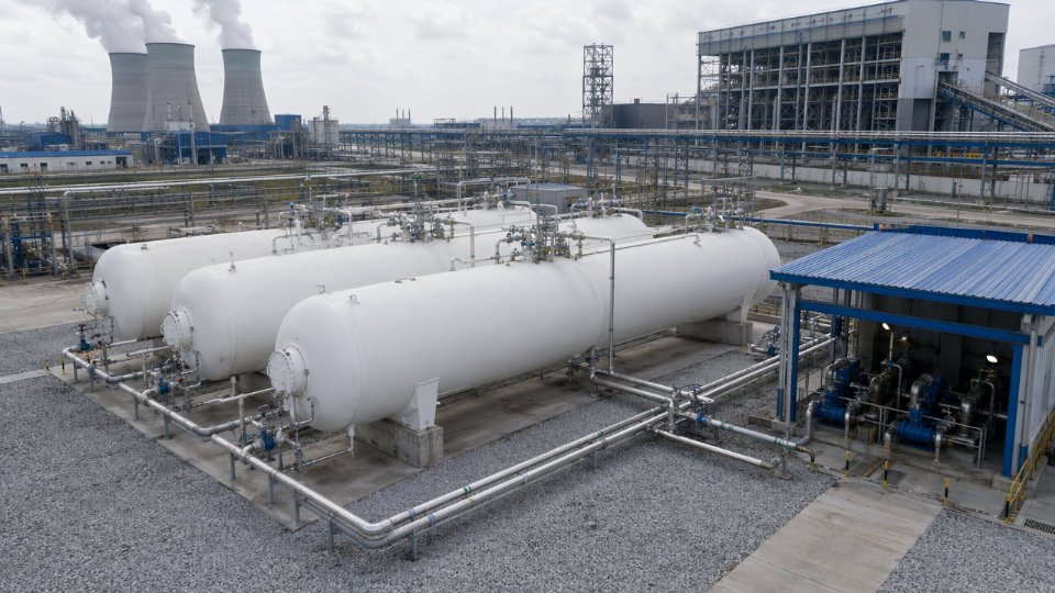
Pressurized Storage Tank Configurations: Bullets, Spheres, and Refrigerated Flat-Bottom Tanks Compared
Three vessel configurations dominate liquid ammonia storage in fertilizer service, and the choice between them is rarely obvious from a datasheet alone. Plot area, total inventory, expansion phasing, site seismicity, and capital budget all pull in different directions. Getting the configuration wrong at the FEED stage means expensive re-engineering or, worse, a facility that can’t expand without rebuilding its storage block.
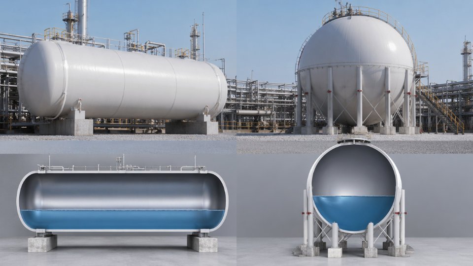
Horizontal Cylindrical Bullets (50 m³ to 500 m³ per Vessel)
Bullets are the workhorse of mid-scale fertilizer plants and expansion projects with phased rollouts. A single vessel can be shop-fabricated, pressure-tested, and delivered in roughly 10 to 18 weeks depending on steel availability and shop loading — meaningfully shorter than either of the alternatives. Wall thickness typically runs 16 mm to 40 mm in Q345R or SA-516 Gr.70, with the actual figure driven by design pressure (commonly 1.6 MPa to 2.5 MPa), vessel diameter, and the corrosion allowance applied — standard practice for ammonia service is 1.5 mm to 3.0 mm.
The real operational advantage of bullets is battery arrangement. Four vessels of 200 m³ each give you 800 m³ total inventory, but they also give you the ability to isolate, inspect, or drain one vessel without shutting down storage entirely. You can add a fifth vessel during a turnaround without touching the rest of the block. That modularity has real value when a plant is expanding urea or nitric acid capacity in stages rather than all at once.
Post-weld heat treatment is not optional for ammonia bullets. Stress corrosion cracking under anhydrous ammonia exposure — particularly if trace moisture or oxygen enters the system during commissioning or maintenance — has caused catastrophic failures historically. PWHT per the applicable code (ASME Section VIII Div.1 or GB 150) reduces residual weld stress and is a hard requirement, not a cost-saving negotiation point.
Spherical Pressure Vessels (500 m³ to 2,500 m³)
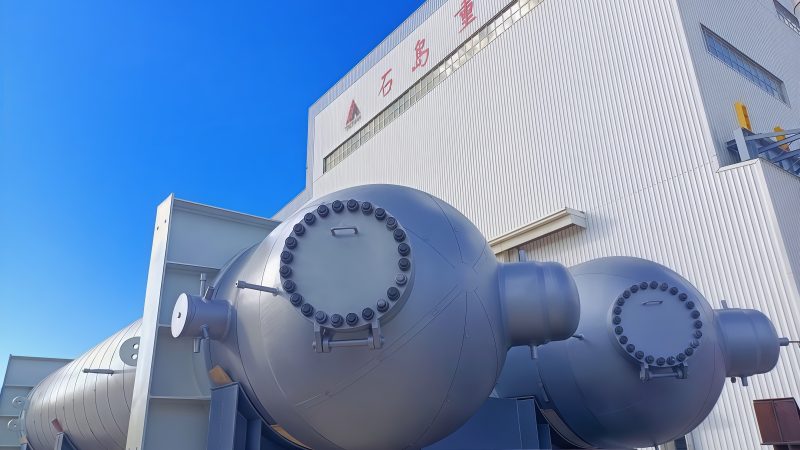
A sphere stores the same volume of ammonia with less steel than any other pressurized geometry — the surface-area-to-volume ratio is at its theoretical minimum, which translates directly to lower material cost per cubic meter of inventory at larger scales. Specific steel weight typically runs 15% to 25% lower than an equivalent-capacity bullet battery, though the actual saving depends on design pressure, wall thickness, and whether you’re comparing against a single bullet or a multi-vessel battery.
The tradeoff is fabrication complexity. Sphere panels require dedicated jig-and-fixture setups, skilled orbital welding, and extensive radiographic examination of curved seam geometry. Shop schedules commonly run 24 to 36 weeks, and not every pressure vessel fabricator can execute them reliably. Lead time risk is real and should be built into project schedules explicitly. Spheres also sit on structural legs rather than saddles, which means civil foundation design is more demanding — soil bearing capacity and seismic zone classification both factor heavily into the support structure cost.
Refrigerated Atmospheric Flat-Bottom Tanks (Near -33°C, Near-Atmospheric Pressure)
Below roughly 5,000 m³ of total inventory, refrigerated flat-bottom tanks are rarely the economic choice. Above that threshold — typical for large complex fertilizer hubs, urea export terminals, or import facilities receiving vessel shipments — they become standard. Operating near atmospheric pressure at approximately -33°C eliminates the high-pressure containment cost entirely, but replaces it with a dedicated refrigeration package, vapor recovery system, and secondary containment bunding. The bund must be sized to hold 110% of the largest tank’s volume in most jurisdictions. Foundation insulation to prevent ground frost heave is another civil cost that catches some projects off guard.
Material selection shifts to low-temperature carbon steel or 9% nickel steel depending on tank size and applicable standard (API 620 Annex R or EN 14620).
Refrigerated flat-bottom ammonia tanks operate at near-atmospheric pressure and therefore require no pressure vessel certification.False
While operating pressure is near atmospheric, these tanks are still subject to design codes such as API 620 and local pressure equipment regulations. Vapor space conditions, boil-off management systems, and associated pipework all carry pressure-rated components requiring formal certification and inspection.
Configuration Comparison at a Glance
| Vessel Type | Typical Capacity Range | Design Pressure | Material Grade | Approx. Specific Steel Weight | Relative Fab Lead Time | Primary Standard |
|---|---|---|---|---|---|---|
| Horizontal bullet | 50–500 m³ per vessel | 1.6–2.5 MPa | Q345R / SA-516 Gr.70 | 35–60 kg/m³ (varies with pressure and diameter) | Shortest (10–18 weeks) | ASME VIII Div.1 / GB 150 |
| Spherical vessel | 500–2,500 m³ | 1.6–2.5 MPa | Q345R / SA-516 Gr.70 | 25–45 kg/m³ | Long (24–36 weeks) | ASME VIII Div.1 / GB 12337 |
| Refrigerated flat-bottom | 5,000 m³ and above | Near-atmospheric | Low-temp carbon steel / 9% Ni steel | 15–30 kg/m³ | Longest (site-built) | API 620 / EN 14620 |
Specific steel weight figures are indicative and depend on design pressure, vessel diameter, corrosion allowance, and applicable code edition. Use them to frame budget conversations, not purchase orders.
One parameter that cuts across all three types and often gets underweighted in early project phases: consequence-based setback distances to occupied buildings and plant boundaries. These are governed by national hazardous chemical regulations and local zoning, and they can constrain which configuration fits a given plot even when the engineering case would point elsewhere. Confirm setback requirements with the local safety authority before finalizing vessel size and arrangement.
Material Selection and Pressure Vessel Design Code Requirements for Ammonia Service
Liquid ammonia is a deceptively straightforward medium until fabrication shortcuts or material substitutions catch up with you — typically at hydrostatic test, at first winter startup, or, worst of all, in service. Getting the material and code selection right before the purchase order is issued saves far more than the marginal cost difference between grades.
Carbon Steel Shell and Head Materials
Three carbon steel grades dominate pressurized ammonia vessel fabrication globally. Q345R per GB 713 is the standard Chinese domestic choice, specified in fine-grain normalized condition for most fertilizer plant bullets and horizontal storage vessels. SA-516 Gr.70 per ASME Section II Part A is its functional counterpart for ASME-coded vessels — widely accepted by international EPC contractors and development bank–funded projects. P265GH per EN 10028-2 covers European-fabricated vessels, though it is less common in Asia-Pacific fertilizer projects. Wall thickness for ammonia bullets typically runs 16 mm to 40 mm depending on vessel diameter, design pressure (generally 1.6 MPa to 2.5 MPa for ambient-temperature storage), and the applicable design code’s joint efficiency factor.
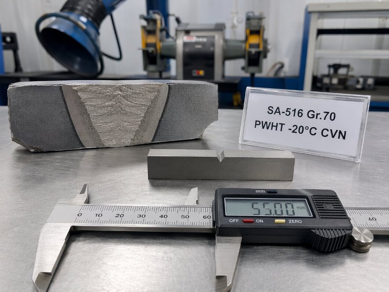
When the design temperature drops below -20°C — relevant for northern Chinese sites, Central Asian plants, and northern European installations — the normalized condition alone is insufficient. Fine-grain normalized or quenched-and-tempered plate is required, and this must be explicitly called out in the material requisition. Receiving normalized plate that was not fine-grain treated is a common mill-supply issue that only surfaces at Charpy impact testing.
Charpy Impact Testing Requirements
Charpy V-notch testing at -20°C with a minimum absorbed energy of 27 J for both base metal and weld metal is a standard procurement requirement for vessels in these climates. Specify this in the vessel data sheet, not just the welding procedure qualification record — otherwise the fabricator may satisfy code minimums without satisfying actual site conditions. Some project specifications tighten this to 34 J or require lateral expansion measurements as well, which is defensible for critical single-train service.
Why Austenitic Stainless Steel Is Avoided for Wetted Parts
316L and 304L are often proposed as upgrades for corrosion resistance, but they are generally inappropriate for liquid ammonia wetted surfaces. Chloride-assisted stress corrosion cracking in austenitic stainless steels is well-documented and the threshold is low — above roughly 1 ppm chloride in the ammonia phase, SCC risk becomes real under residual fabrication stress. Fertilizer-grade anhydrous ammonia is rarely certified at that chloride level throughout a tank’s operating life, and contamination events during transfer or product changeover are not hypothetical. Carbon steel in dry anhydrous ammonia service is actually less susceptible to this failure mode.
Austenitic stainless steels such as 316L are a safe upgrade material for liquid ammonia storage vessel shells.False
Austenitic stainless steels are vulnerable to chloride-assisted stress corrosion cracking in ammonia service. Carbon steel grades such as Q345R or SA-516 Gr.70 are the industry-standard choice for pressurized ammonia vessels, and most engineering codes and procurement specifications explicitly restrict or prohibit stainless steel for ammonia wetted parts unless chloride levels are demonstrably and continuously controlled below 1 ppm.
PWHT, Nozzle Materials, and Prohibited Alloys
Post-weld heat treatment under GB 150 requires full furnace heat treatment at 600°C to 640°C for carbon steel shells exceeding the thickness threshold — typically 32 mm, though project-specific regulatory requirements can lower that threshold. ASME VIII Div.1 UCS-56 provides equivalent guidance for ASME-coded vessels. Local PWHT with ceramic resistance pads is not an acceptable substitute for full furnace treatment on ammonia vessels; the residual stress profile from local heating is uneven and leaves HAZ regions vulnerable.
Nozzle and fitting materials must be fully consistent with the shell certification — matching plate or forged stock from the same certified heat, not sourced opportunistically. Forged flanges to ASME B16.5 Class 300 or HG/T 20592 PN25/PN40 are the correct standard for ammonia service connections in the 1.6 MPa to 2.5 MPa range. Cast iron and copper-bearing alloys are prohibited without exception: cast iron lacks the ductility to handle thermal cycling and pressure surge, while copper forms explosive copper azide compounds with ammonia.
Third-Party Inspection Holdpoints
International EPC contractors and project lenders increasingly mandate third-party inspection by recognized bodies — Bureau Veritas, TÜV Rheinland, SGS, or the China Special Equipment Inspection Institute — at three stages: mill plate certification, fabrication (including weld examination and dimensional checks), and hydrostatic test witness. Treating TPI as a formality rather than a genuine quality gate is where projects accumulate problems that surface during commissioning. A fabricator who resists mill-stage inspection is telling you something worth listening to before the vessel is half-built.
Liquid Ammonia Transfer Pump and Compressor Selection: Flow, NPSH, and Seal System Criteria
Pump and compressor selection is where a significant share of liquid ammonia plant expansion problems originate. Engineers who have sized water-service or hydrocarbon pump systems often underestimate how unforgiving ammonia is: its low viscosity, high vapor pressure, and acute toxicity mean that a marginal NPSH calculation or a wrong seal material choice translates directly into either a release event or chronic cavitation damage. Getting this right at the datasheet stage is far cheaper than the alternative.
Centrifugal Pumps: The Workhorse Above 30 m³/h
For bulk transfer duties — tank-to-tank transfers, loading arms, evaporator feed — enclosed-impeller centrifugal pumps dominate once flow rates exceed roughly 30 m³/h. The enclosed impeller configuration is not optional in ammonia service; it maintains tighter clearances, reduces recirculation at partial load, and limits the internal vapor generation that triggers cavitation under high vapor-pressure conditions.
Seal system selection is the single most consequential decision on a liquid ammonia centrifugal pump specification. Canned-motor and magnetic-drive configurations eliminate the dynamic shaft seal entirely, and this matters operationally: shaft seal failure is the primary failure mode responsible for ammonia releases at pump stations. Where plot space and lifecycle cost allow, sealless designs should be the default recommendation for any pump handling liquid ammonia at ambient or elevated temperatures. If a conventional dual mechanical seal configuration is specified instead — typically in high-flow, high-head duties where canned-motor options become less practical — the seal flush plan must use a barrier fluid compatible with ammonia, and elastomers must be EPDM or PTFE. No Buna-N, no neoprene. Both swell and degrade in ammonia service within weeks.
NPSHa Calculation: Where Errors Accumulate
The NPSHa calculation for liquid ammonia is more demanding than for most process fluids because the vapor pressure is high and temperature-sensitive. At 30°C, liquid ammonia vapor pressure sits around 1.17 MPa — a figure that shifts materially with even a 5–10°C rise in ambient or process temperature. The NPSHa equation must account for three terms simultaneously: the static suction head from the tank bottom outlet to the pump centerline (typically 1.5 m to 4 m on a horizontal bullet installation, depending on saddle height and grade), the vapor pressure at the maximum anticipated operating temperature, and actual piping friction losses through suction-side block valves, strainers, and fittings.
A minimum NPSHa margin of 0.5 m above the pump manufacturer’s NPSHr is a common engineering floor, but several EPC specifications for ammonia service push this to 1.0–1.5 m when the suction temperature can vary significantly with seasonal ambient swings. Applying the tighter margin costs nothing at design stage and avoids chronic partial-cavitation damage that manifests as impeller pitting over 12–18 months of operation.
A minimum NPSHa margin of 0.5 m above NPSHr is sufficient for all liquid ammonia pump applications.False
0.5 m is a recognized engineering minimum, but projects with variable suction temperatures or long suction piping runs frequently specify 1.0–1.5 m margins. The required margin depends on fluid temperature range, piping geometry, and the pump curve's sensitivity to NPSH degradation — not a single universal threshold.
Reciprocating Diaphragm Pumps for Dosing and High-Pressure Injection
At flow rates below roughly 5 m³/h and discharge pressures up to 25 MPa — ammonia dosing to synthesis converter feed streams is a typical case — reciprocating diaphragm pumps are the correct selection. The diaphragm completely isolates the pumped fluid from the drive mechanism, which eliminates the plunger seal leakage path. Flow accuracy at low rates is also substantially better than a centrifugal machine operating far off its best-efficiency point. Specify API 674 or the equivalent GB/T standard, and confirm diaphragm material compatibility with anhydrous ammonia before order placement.
Vapor Return Lines and Compressor Sizing
Vapor return line sizing is chronically underspecified on expansion projects. During truck or railcar unloading, liquid ammonia displaces an equivalent vapor volume in the storage bullet. If the vapor return line is undersized — a common outcome when the original storage design was not sized for the expanded unloading rate — backpressure builds faster than the relief system expects, and overpressure events during unloading become a documented operational risk. Size the vapor return line for the maximum unloading flow rate, not the average, and account for the full vapor generation rate at the highest anticipated liquid temperature during transfer.
Transfer compressors — reciprocating or oil-injected screw types, depending on capacity and compression ratio — handle vapor-phase ammonia recovery, pressure equalization between storage vessels, and refrigeration duty on semi-refrigerated storage systems. Selection inputs include volumetric flow in m³/h at suction conditions, the required compression ratio (typically 2:1 to 5:1 on pressure-equalization duty, higher on refrigeration circuits), and shaft seal or labyrinth design rated for ammonia vapor. Labyrinth seals with nitrogen purge are a common choice on larger reciprocating units; they avoid the elastomer compatibility problem entirely.
Datasheet and Material Exclusions
Every pump and compressor datasheet submitted for EPC approval should explicitly reference the applicable standard — API 610 for centrifugal pumps, API 674 for reciprocating pumps, or the corresponding GB equivalent — and include a materials-of-construction table that lists ammonia-compatible elastomers and calls out prohibited materials by name. Bronze, brass, zinc alloys, and cadmium-plated fasteners are all prohibited in ammonia service due to stress corrosion cracking and direct chemical attack. These exclusions are not always caught by a standard vendor datasheet review; they must be specified as hard rejection criteria in the purchase requisition.
| Component | Recommended | Prohibited |
|---|---|---|
| Pump casing / impeller | Carbon steel, 316 SS | Bronze, brass, zinc alloys |
| Elastomers / seals | EPDM, PTFE | Buna-N, neoprene, natural rubber |
| Fasteners | Carbon steel, A193 B7 | Cadmium-plated, zinc-plated |
| Gaskets | Spiral-wound PTFE-filled | Cork, rubber sheet |
Piping, Valves, and Loading/Unloading Arm Specifications for Ammonia Transfer Circuits
Piping and valve specifications are where expansion projects most frequently develop scope gaps. An engineer can size a storage tank correctly and still face a costly rework when the interconnecting piping class is underspecified or the loading arm vendor supplies hardware intended for LPG rather than anhydrous ammonia service. Getting the interconnecting scope right in early FEED saves weeks of re-procurement.
Piping Class and Weld Examination Requirements
Liquid ammonia transfer circuits are almost universally designated Class 300 ANSI or PN40 in plant piping specifications, which sets the pressure-temperature envelope for fittings, flanges, and valve bodies. Seamless carbon steel pipe — ASTM A106 Gr.B for ASME-coded plants, or GB 8163 20# steel for GB 150 plants — is the standard choice. Seamless rather than ERW is non-negotiable here: the longitudinal weld seam in ERW pipe introduces a stress concentration that ammonia’s propensity to cause stress corrosion cracking will exploit over time.
All butt-welded joints must receive 100% radiographic examination. Spot RT, which is acceptable on utility piping, is not appropriate for ammonia service regardless of what a cost-constrained schedule pressure might suggest. Welder qualification records and weld procedure specifications should be reviewed before fabrication begins, not during pre-commissioning inspection.
Valve Trim Selection
Ball valves with full-bore or reduced-bore carbon steel bodies dominate isolation service. Seat material matters more than many specifications acknowledge: PTFE is acceptable for ambient-temperature pressurized service, while PEEK seats offer better resistance at the temperature cycling seen near refrigerated storage or during depressurization events. Fugitive emission certification to ISO 15848-1 Class BH — or a demonstrably equivalent standard — is required at the stem. On a facility handling hundreds of tonnes of ammonia, Class BH leakage limits (below 50 ppm·m³/s per stem) meaningfully reduce chronic atmospheric release and limit personnel exposure in enclosed valve galleries.
Globe valves are specified for control and throttling service, not ball valves. Using a ball valve in a partially open position for flow control accelerates seat erosion and creates cavitation risk in two-phase flow conditions near the pump suction.
Pressure Relief Valve Sizing
Spring-loaded PRVs on liquid ammonia vessels require two-phase relief calculations for any fire-exposure scenario. A purely vapor-phase calculation will undersize the valve because flashing liquid generates significantly higher volumetric flow at the relief device inlet. API 520/521 provides the accepted methodology; GB/T 12241 is the corresponding Chinese standard. PRV inlet and outlet piping must be designed to limit pressure drop to the code-prescribed limits — typically 3% of set pressure on the inlet side — since exceeding this causes chattering and rapid seat wear.
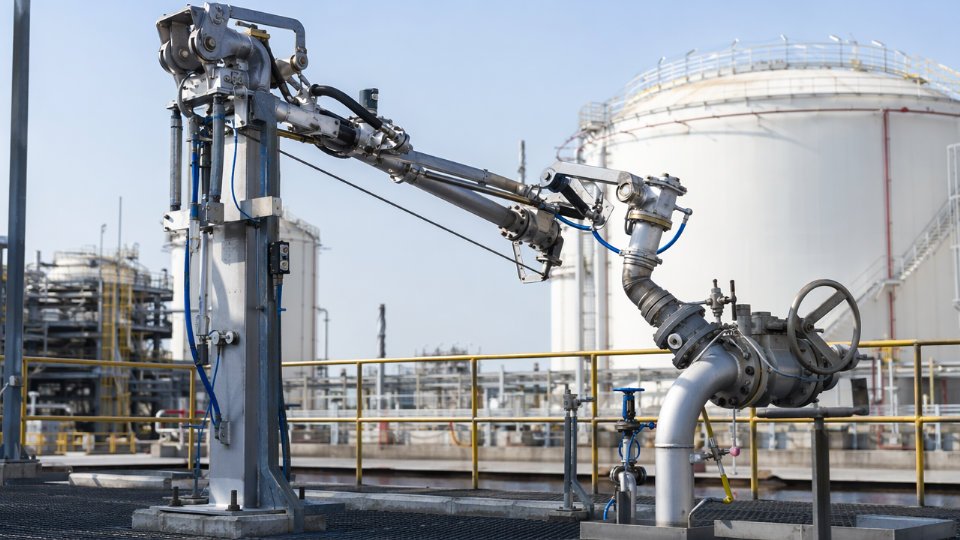
Loading and Unloading Arms
Top-loading and bottom-loading arms for road tanker and railcar service should be engineered to EN 13480 structural requirements and OCIMF guidance adapted for high-vapor-pressure, toxic service. Dry-disconnect couplings at the hose-to-vehicle connection point are mandatory — not optional equipment. A single uncontrolled disconnection during unloading can release enough vapor to trigger emergency evacuation and regulatory reporting. The coupling must be rated for the full working pressure of the circuit, not just the tanker’s own relief pressure.
Excess Flow Valves and Passive Protection
Excess flow valves installed directly at tank nozzle outlets provide the last passive barrier against large-bore piping failure. Sizing should be based on maximum normal operating flow plus a 20% to 30% margin, with the closure set point chosen to discriminate between surge conditions and genuine line rupture. Undersizing produces nuisance closure during pump startup; oversizing defeats the protective function entirely.
Excess flow valves eliminate the need for emergency isolation valves on ammonia tank outletsFalse
EFVs respond to high-flow pipe rupture scenarios but cannot substitute for remotely operated emergency isolation valves, which handle blockages, slow leaks, and operator-initiated isolation during incidents where flow may not exceed the EFV set point.
Thermal Contraction and Pipe Support Design
Thermal movement is underestimated on pressurized ammonia circuits more often than on refrigerated ones, because the temperature differential looks smaller on paper. Even dropping from 35 °C ambient to the –33 °C liquid temperature at a refrigerated tank connection produces contraction in the 50 mm to 80 mm range per 50 m of pipe run, depending on pipe material and actual operating temperature. Expansion loops, cold-spring design, or engineered expansion joints must be specified explicitly in the pipe stress analysis — not left to the support contractor to resolve during installation. Supports must be designed to accommodate this movement without imposing unacceptable nozzle loads on tank connections, where any stress concentration near the shell-to-nozzle weld becomes a long-term integrity concern.
Safety System Integration: Relief, Flare, Leak Detection, and Emergency Shutdown Architecture
Liquid ammonia storage carries a hazard profile that sits outside the envelope of standard petrochemical safety design. Getting the safety architecture wrong — even partially — means regulators can halt an expansion mid-commissioning, and the cost of retrofitting a dedicated relief header after concrete is poured typically exceeds the cost of doing it correctly in FEED by a factor of five or more.
Dedicated Ammonia Relief Header and Disposal System
Ammonia cannot share a hydrocarbon flare header. The reasons are both chemical and regulatory. Combustion characteristics differ sharply: ammonia has a narrow flammability range (15–28% v/v in air) and an autoignition temperature well above most hydrocarbons, which creates flame stability problems in a conventional flare tip designed for mixed hydrocarbon streams. More critically, co-mingling with hydrocarbon vapors can produce localized toxic-flammable mixtures with unpredictable dispersion behavior. Most national pressure vessel and hazardous chemical regulations, along with OSHA PSM requirements where applicable, treat this as a hard separation requirement, not a design preference.
The ammonia relief header routes to one of two disposal endpoints: a packed-bed water scrubber or an elevated atmospheric vent stack. Water scrubbers are preferred for continuous or high-frequency minor relieving — the packed bed absorbs ammonia into an aqueous solution that can be neutralized on-site. Elevated vent stacks are acceptable for infrequent major relief events, provided a dispersion model confirms that worst-case release concentrations fall below the IDLH of 300 ppm at grade level, accounting for site wind rose data, local terrain, and plant boundary distances. Relying on a generic dispersion calculation without site-specific meteorological input is a common shortcut that later fails regulatory review.
Leak Detection Layout and Voting Logic
Electrochemical point detectors are the industry standard for ammonia gas monitoring. A functional detector array covers three alarm thresholds: 25 ppm (TLV-TWA, personnel awareness), 150 ppm (action level, personnel evacuation), and a third setpoint near 300 ppm that feeds ESD initiation. Detection zones are placed at grade around tank skirts, pump suction and discharge manifolds, compressor enclosures, and loading/unloading positions — ammonia vapor is lighter than air at elevated temperatures but near-neutral buoyancy in cold ambient conditions, so low-level placement remains appropriate for leak events from ground-level flanges and seals.
Voting logic for ESD initiation typically uses a 2-out-of-3 (2oo3) configuration per zone. This prevents a single detector fault from triggering a plant-wide shutdown while ensuring a genuine release doesn’t go unacknowledged. Detector calibration and bump-test intervals should be written into the instrument maintenance plan at purchase — electrochemical sensors degrade predictably, and a neglected calibration schedule is one of the most common audit findings in ammonia plant HSE reviews.
ESD Valve Specification and SIL Requirements
Liquid outlet lines from storage tanks require ESD valves rated to SIL 2 per IEC 61511. In practice, this means pneumatically actuated, fail-closed ball valves with spring-return actuators capable of full closure in under 10 seconds on signal loss. The spring-return design matters: a solenoid-only actuator depends on instrument air or electrical power to close, which fails the fail-safe requirement under a simultaneous utility loss and release scenario. Proof test intervals for SIL 2 devices in this service typically fall in the 12–24 month range depending on the PFD (probability of failure on demand) calculations from the SIL verification study.
SIL 2-rated ESD valves on liquid ammonia storage outlets must achieve closure on loss of instrument signal, not only on active command.True
IEC 61511 fail-safe requirements mandate that safety instrumented functions achieve their safe state upon energy or signal loss. A valve that closes only on active command does not satisfy the fail-safe criterion and would not pass functional safety verification.
Deluge Water Curtain Systems
Water curtain systems around the tank farm perimeter serve a vapor knock-down function, not fire suppression in the conventional sense. Ammonia does not behave like a flammable hydrocarbon fire; the water curtain primarily absorbs and dilutes vapor clouds drifting toward plant boundaries or ignition sources. Design spray density of 10.2 L/min·m² appears in NFPA 15 guidance and several national standards as a baseline, but this number is only a starting point. Sites with prevailing winds above 4–5 m/s, unusual terrain channeling, or short distances to plant fence lines should validate curtain effectiveness through CFD or Gaussian dispersion modeling. Specifying the system from a data sheet alone without dispersion confirmation is a recurring design gap on greenfield expansions.
HAZOP, LOPA, and PSV Inspection Scheduling
HAZOP and LOPA conducted during FEED should address four specific liquid ammonia loss scenarios that EPC teams frequently underweight: tank overfill, pump mechanical seal failure, loading arm inadvertent disconnection under pressure, and external fire exposure driving tank vapor space pressure rise. Tank overfill is typically handled with a SIL 2 instrumented high-high level function that independently closes the fill valve and initiates ESD — independent from the basic process control system level loop, not sharing the same transmitter. Pump seal failure scenarios should inform the sealed drain system design and whether a seal pot with a local gas detector is required at each pump.
PSV inspection intervals for liquid ammonia service run from 2 years to 4 years depending on the governing regulation — NBIC Part 2 provides one framework, while Chinese TSG standards and European PED-aligned national codes each specify their own intervals. The equipment data package delivered at project handover should explicitly state the governing code, the required inspection interval, the lift pressure, and the relief area calculation basis. Leaving this to the end-user to reconstruct from first principles after commissioning adds unnecessary risk to an already tightly scheduled plant startup.
Fabrication Quality Control, Inspection Milestones, and Factory Acceptance Testing for Ammonia Vessels
Buying a liquid ammonia pressure vessel is not the same as buying structural steel. The failure modes are severe — catastrophic brittle fracture, stress corrosion cracking, and undetected weld defects that survive pressure test but propagate under cyclic service — and by the time you discover a fabrication shortcut, the vessel is already on-site or worse, in service. A rigorous Inspection and Test Plan, agreed between purchaser and vendor before fabrication starts, is the single most effective tool procurement and quality engineers have.
Structuring the ITP: Hold Points vs. Witness Points
The ITP for a liquid ammonia pressure vessel should be a numbered matrix, not a narrative document. Every significant activity carries a classification: a Hold Point (HP) stops fabrication until the purchaser or third-party inspection body signs off; a Witness Point (WP) requires notification and attendance where practical, but does not halt progress if the inspector cannot attend.
Minimum HP designations for ammonia service vessels: material receiving inspection with Material Test Report (MTR) review against the purchase specification, fit-up and dimensional check before any root pass is laid, Weld Procedure Qualification Record (WPQR) and Welder Qualification review prior to production welding, post-weld heat treatment (PWHT) furnace chart review, and the hydrostatic pressure test. Non-destructive examination completion and the final dimensional inspection are typically WP unless the project risk classification or insurer requires full hold status. Negotiate these classifications explicitly in the ITT; vendors who resist HP designations at hydrostatic or PWHT stages should be noted.
NDE Requirements and Weld Category Coverage
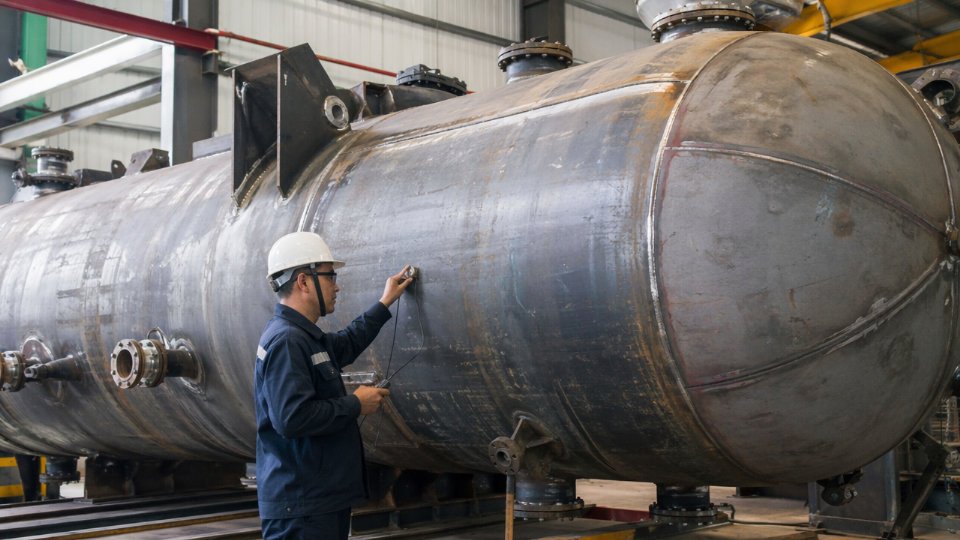
Radiographic examination (RT) or phased-array ultrasonic testing (PAUT) of all Category A and B welds — longitudinal and circumferential shell seams, head-to-shell joints — is the baseline for ammonia vessel classification. For shells above roughly 30 mm wall thickness, or whenever the operating environment raises SCC concern, 100% RT or 100% PAUT is the practical standard. PAUT has largely replaced film RT on thick sections in modern shops because it produces a permanent digital record and resolves volumetric defects with better depth accuracy, but confirm the procedure is qualified under ASME Section V or the applicable equivalent.
Magnetic particle testing (MT) or liquid penetrant testing (PT) on all nozzle attachment welds, saddle welds, and any weld repair excavations closes the surface inspection loop. Do not accept a vendor who proposes to defer these to a single campaign at the end of fabrication; they should be concurrent with fit-up stages.
Hydrostatic Test Execution
Test pressure under ASME VIII UG-99 runs 1.3× to 1.5× the maximum allowable working pressure (the multiplier depends on code edition and stress ratio); GB 150 clause 10 specifies 1.25× design pressure as the floor for most pressure vessel classes. Either way, the test is only valid if executed correctly. Water chloride content must stay below 25 ppm — this is not a paperwork requirement, it is a metallurgical one. Austenitic stainless components in the system (instrument connections, some nozzle liners) will initiate chloride-induced SCC at concentrations that look harmless on a standard water analysis. Require a written water quality certificate from the test medium source.
Tap water from municipal supplies is acceptable for hydrostatic testing of ammonia vessels without analysis.False
Municipal tap water chloride content varies widely by region and season — values above 100 ppm are common — which creates SCC risk for any austenitic stainless components in contact during the test. Water quality must be verified by analysis before the test begins.
All external surfaces must be dry and accessible during the pressure hold period. Insulation, fireproofing, and any temporary protective wrapping must be removed. Wet surfaces mask seepage; a vessel that passes a wet-lagged hydro test tells you very little.
Surface Preparation, Coating, and Internal Cleanliness
External surfaces require blast cleaning to Sa 2.5 minimum per ISO 8501-1 before primer application. A two-coat system — epoxy primer plus polyurethane or epoxy topcoat — is standard for outdoor atmospheric service, with dry film thickness depending on the site corrosivity category, typically ranging from 120 µm to 250 µm total DFT. Measure DFT at minimum 5 readings per square meter on complex geometries; holiday testing on nozzle necks and saddle contact zones catches the defects that brush application misses.
Internal carbon steel surfaces are not coated for ammonia service — liquid anhydrous ammonia is itself not corrosive to clean steel — but they must be free of mill scale, rust, weld spatter, and all moisture before first filling. Any residual water initiates corrosion and, critically, introduces water contamination into the ammonia inventory, which downstream process operations will detect immediately. Internal cleanliness is a final inspection line item, not an assumption.
Dimensional Verification and the MDR Package
Shell out-of-roundness, head-to-shell alignment, nozzle orientation tolerances, and nozzle projection dimensions must all be measured against certified fabrication drawings and recorded before shipment. These are not formalities — a nozzle orientation error of even a few degrees forces field modification of piping spools and loading arms, which on a live expansion project translates directly to schedule delay.
The Manufacturer’s Data Record delivered with each vessel should contain: all MTRs traceable to heat and lot numbers, the complete weld map, NDE reports with film or digital data files, PWHT time-temperature charts, hydrostatic test records, nameplate photographs, the dimensional inspection report, and the certificate of conformance signed by the authorized inspection body (AI or TPI). Verify this package is complete before final payment release. An incomplete MDR is not a paperwork inconvenience — it is a barrier to local statutory registration, insurance coverage, and future re-rating or repair authorization.
EPC Procurement Workflow: Vendor Qualification, Lead Times, and Logistics Planning for Ammonia Equipment Packages
Procurement for liquid ammonia equipment packages is where technically sound engineering specifications routinely collide with project schedule reality. Getting the sequence wrong — qualifying vendors late, underestimating fabrication windows, or ignoring transport permit lead times — pushes ammonia storage onto the critical path of an entire fertilizer expansion. The consequences are not abstract: delayed tank delivery has held up urea plant commissioning by eight to fourteen weeks on projects where foundation work finished ahead of the vessel.
Vendor Qualification: What to Verify Before Issuing an ITT
The minimum qualification threshold for liquid ammonia pressure vessels is a valid manufacturing license covering the hazard class. In China, that means a TS certificate for Class III pressure vessels issued by the State Administration for Market Regulation; fabricators holding only Class I or II scope cannot legally manufacture these vessels regardless of their general shop capability. For export projects or plants operating under international codes, an ASME U-stamp with documented ammonia-service fabrication history is the baseline. Neither certificate alone is sufficient evidence of actual competence — a shop can hold a U-stamp and still lack the welding procedure qualifications, PWHT furnace capacity, or NDE staffing to execute a large ammonia bullet without quality problems.
Beyond the license, require documented delivery records for ammonia or similarly toxic compressed-gas service (hydrogen sulfide, chlorine, or LPG vessels are reasonable analogues), audit results from your own QA team or a recognized third-party inspection agency within the past two to three years, and confirmation that the vendor has a standing relationship with an accredited NDE contractor rather than subcontracting it ad hoc. Vendors who cannot produce radiographic or UT records from recent comparable vessels are a procurement risk regardless of price.
An ASME U-stamp certifies a manufacturer's quality system and code compliance capability, but does not itself certify that the manufacturer has fabricated vessels for toxic compressed-gas service.True
The U-stamp authorization covers design and fabrication to ASME Section VIII; service-specific experience — particularly for hazardous media like liquid ammonia — must be verified separately through reference projects and material traceability records.
Realistic Fabrication Lead Times and What Drives Them
Horizontal bullets in the 50–200 m³ range typically require 14 to 20 weeks from purchase order to ex-works, assuming plate material is procured immediately at PO and no major revision cycles occur on drawings. That window compresses toward 14 weeks for simple single-compartment vessels at the lower capacity end, and extends toward 20 weeks when full radiography, PWHT, and third-party witness hold points are required — which they should be on ammonia service.
Large spheres in the 500–2,000 m³ range are a different category entirely. Shell plate forming, assembly sequencing, and post-weld heat treatment for spherical vessels of this scale realistically require 28 to 40 weeks. Schedule pressure from EPC teams that assume sphere fabrication can match bullet lead times is a recurring source of project delay. Complete pump station skids — including the baseplate, driver, mechanical seal system, and local control panel — run 18 to 26 weeks depending on seal vendor lead times, which have been volatile in recent procurement cycles.
None of these windows include ocean freight, port clearance, or site installation. On export projects from Asia to the Middle East, East Africa, or South America, add eight to sixteen weeks for sea freight and customs depending on destination port efficiency and whether an open-top or flat-rack container is available at the load port.
Heavy Transport and Lift Planning
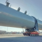
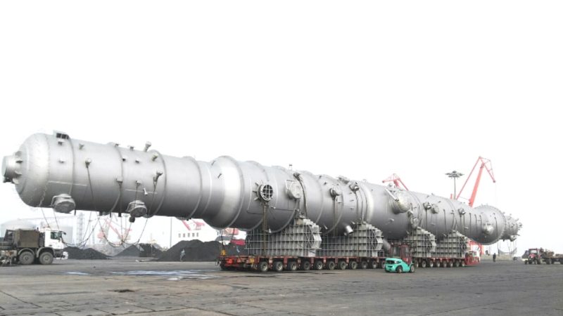
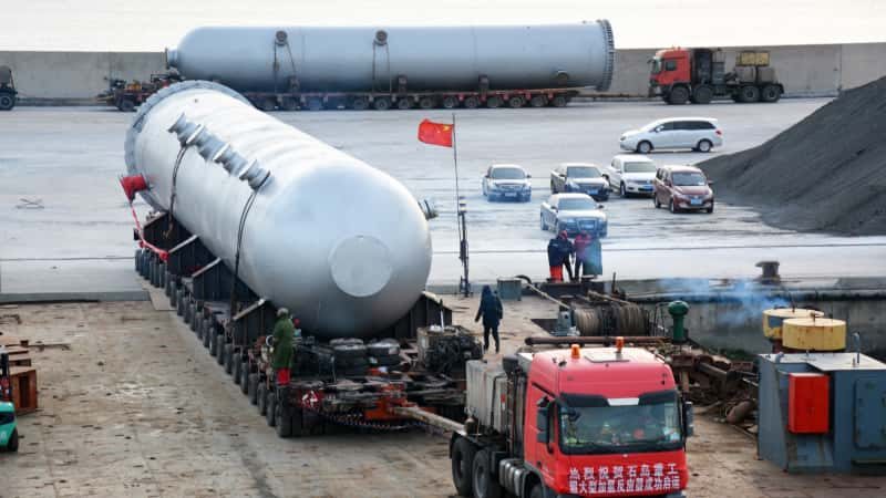
A 200 m³ liquid ammonia bullet typically ships at 40 to 90 tonnes depending on wall thickness and saddle configuration; a 1,000 m³ sphere can reach 150 to 200 tonnes. At those weights, road transport from the fabrication shop to the port or directly to site is a permitted oversize move in virtually every jurisdiction. Route surveys, bridge load assessments, utility line lift coordination, and escort vehicle procurement take four to ten weeks depending on the country and the route complexity. Procurement teams that initiate transport planning only after vessel completion routinely find that permit approval adds three to six weeks of yard storage time at the fabricator — at daily storage charges.
Confirm saddle design, lifting lug positions, and center-of-gravity calculations with the shipping contractor before fabrication drawing approval, not after. Changing lug positions after shell assembly is a weld repair and re-inspection event, not a minor revision.
Spare Parts and Close-Out Provisioning
A minimum two-year operational inventory is standard EPC contract language, but the actual bill of materials behind that phrase is frequently underdefined at handover. At minimum, specify: one complete mechanical seal cartridge assembly per transfer pump (not just the seal faces), one full set of PRV internals per relief valve sized for the expected setpoint, PTFE envelope gaskets and bolt sets for all flanged joints in ammonia service, and one spare excess flow valve per tank outlet nozzle. These items have lead times of their own — proprietary seal cartridges from European manufacturers can run eight to fourteen weeks — and ordering them as an afterthought at mechanical completion creates a commissioning vulnerability.
Schedule Integration Across Packages and Export Compliance
On multi-package projects, the ammonia storage package, the refrigeration package, and civil foundation works must be scheduled as an interdependent logic network, not as parallel workstreams that converge at installation. Tank foundation concrete requires a minimum 28-day cure before vessel setting loads are applied; on large sphere foundations, the cure and pre-loading inspection sequence can extend that to 35 to 42 days. Vessel delivery arriving at site before the foundation is certified ready-to-receive forces either temporary storage (a cost and risk event) or a schedule hold that propagates downstream into piping and instrument installation.
Export compliance deserves a pre-bid assessment, not a pre-shipment scramble. Liquid ammonia vessels above certain capacity and pressure thresholds may fall within dual-use equipment classifications under the US Export Administration Regulations, EU Regulation 2021/821, or equivalent national controls, depending on end-user country and stated application. An end-user certificate, denial order screening, and in some cases an export license application must be completed before shipment — a process that can take four to twelve weeks once initiated. Starting this review during bid evaluation rather than at purchase order close avoids a scenario where a fabricated vessel sits in a bonded warehouse while compliance documentation is assembled.
Frequently Asked Questions: Liquid Ammonia Storage and Transfer Equipment for Fertilizer Plants
What is the maximum capacity of a single pressurized liquid ammonia bullet, and when should a sphere be specified instead?
Horizontal bullets are practically limited to roughly 400–500 m³ per vessel. That ceiling is not a design code restriction — it is a transportation reality. A bullet in that size range already approaches 150–200 tonnes gross weight depending on wall thickness, and overland movement on low-loaders becomes a logistics project in its own right once you exceed those figures. Road permit requirements, bridge load limits, and route surveys all drive cost and schedule.
Above roughly 500 m³ single-vessel inventory, a sphere becomes the more rational choice. A sphere minimizes steel tonnage for a given volume because the geometry offers the most favorable surface-area-to-volume ratio of any pressure vessel shape. For large single-vessel inventories — think 1,000 m³ and above — the steel savings can offset the more complex fabrication and the cost of the structural support legs. Spheres also present a smaller plot footprint per cubic meter of storage, which matters on constrained brownfield expansion sites. The trade-off is that spheres are always field-fabricated, so your inspection and welding quality control burden shifts to site rather than the controlled shop environment.
Is carbon steel acceptable for liquid ammonia service, or must stainless steel be used?
Carbon steel — Q345R under GB 150 or SA-516 Gr.70 under ASME Section VIII — is not just acceptable; it is the standard and preferred choice for liquid ammonia pressure vessels. Austenitic stainless steels are actively avoided for wetted components. The reason is stress corrosion cracking (SCC): austenitic grades are susceptible in the presence of trace oxygen or moisture in the ammonia stream, and achieving the purity and oxygen-exclusion conditions necessary to suppress that mechanism is operationally difficult to sustain over a vessel’s full service life.
Austenitic stainless steel is a safer material choice than carbon steel for liquid ammonia vessels.False
Austenitic stainless steels are more susceptible to stress corrosion cracking in ammonia service when trace oxygen or moisture is present. Carbon steel grades such as Q345R and SA-516 Gr.70 are the industry-standard materials for liquid ammonia pressure vessels and are preferred by major design codes.
Post-weld heat treatment (PWHT) of carbon steel vessels is required by both GB 150 and ASME VIII Div.1 above certain wall thickness thresholds, and it also reduces residual weld stresses that could otherwise contribute to hydrogen-induced cracking mechanisms over time. Specify PWHT regardless of whether the code strictly mandates it for your wall thickness — the marginal cost is small relative to the risk.
What NDE methods are required for ammonia vessel welds?
Full radiographic testing (RT) or phased-array ultrasonic testing (PAUT) of all main longitudinal and circumferential seam welds is standard practice, and both ASME VIII and GB 150 require 100% volumetric examination for Class III (GB) or vessels in certain service and design pressure categories. PAUT has largely displaced film RT on new fabrications at most competent shops because it produces a digital record, detects planar flaws more reliably, and eliminates radiation safety management on the shop floor.
Nozzle fillet welds and structural attachment welds receive magnetic particle testing (MT) on ferritic materials, or liquid penetrant testing (PT) where MT is impractical. Hardness testing after PWHT confirms that heat-affected zone hardness stays within code limits — typically below 200 HBW for ammonia service. Do not accept a mill test report as a substitute for in-process hardness checks at welds.
How is NPSHa calculated for liquid ammonia transfer pumps, and what margin is required?
NPSHa = (absolute pressure at liquid surface) − (vapor pressure of ammonia at pumping temperature) + (static head from liquid surface to pump centerline) − (friction losses in suction piping).
The calculation is straightforward but the errors are consistent. Engineers underestimate suction line friction losses, forget to account for the lowest credible tank level at end-of-drawdown, and use standard atmospheric pressure rather than the actual tank operating pressure at minimum conditions. For liquid ammonia at 20°C, vapor pressure is approximately 0.86 MPa absolute — any suction piping design that is not generous in diameter will erode NPSHa quickly.
Most engineering specifications require NPSHa to exceed the pump’s NPSHr by a minimum margin of 0.5 m to 1.0 m. Some operators and licensors push that to 1.5 m for ammonia service given the consequences of cavitation-induced seal damage and the flammability and toxicity hazard of any resulting leak. The required margin depends on pump type, speed, and suction specific speed — confirm it with the pump vendor’s certified curve, not the preliminary datasheet.
What certifications should a liquid ammonia pressure vessel manufacturer hold for international EPC projects?
For ASME-code projects, the U-stamp under Section VIII Div.1 is the baseline certification; the manufacturer must hold a current ASME Certificate of Authorization, and the National Board registration (NB stamp) is expected if the vessel will be registered in a North American jurisdiction. European projects require PED 2014/68/EU conformity and CE marking, with a Notified Body involved in design review and final inspection for Category III equipment — which liquid ammonia vessels at typical fertilizer plant operating pressures will be.
Chinese manufacturers supplying domestic projects require the TS (special equipment) manufacturing license for Class III pressure vessels issued by SAMR. For export projects, the TS license does not substitute for ASME or PED certification, and buyers should verify that the manufacturer holds both concurrently if dual compliance is needed.
Third-party inspection body involvement — Bureau Veritas, TÜV SÜD, Lloyd’s Register, or similar — provides independent weld and dimensional verification that is separate from the code certification. International EPC clients routinely require this as a contract condition, and experienced manufacturers will already have standing TPI agreements in place.
What setback distances are required between a liquid ammonia storage tank farm and occupied plant buildings?
There is no single universal figure, and any supplier or consultant who quotes you a fixed number without referencing a consequence model should be challenged. Setback distances must be derived from site-specific dispersion modeling using actual meteorological data, worst-case release scenarios, tank inventory, and the regulatory framework of the project jurisdiction.
That said, guidance documents including CCPS Guidelines for Chemical Process Quantitative Risk Analysis and China’s GB 50016 fire code produce results that, for pressurized ammonia bullets in the 100–500 m³ range, commonly fall in the 30 m to 100 m range from occupied buildings. Larger inventories, higher-wind-probability sites, or facilities adjacent to public areas will require quantitative risk assessment (QRA) that may push those distances considerably further. Build the consequence modeling scope into the FEED phase — waiting until detailed engineering to discover that your tank farm location violates the QRA criteria is an expensive mistake.