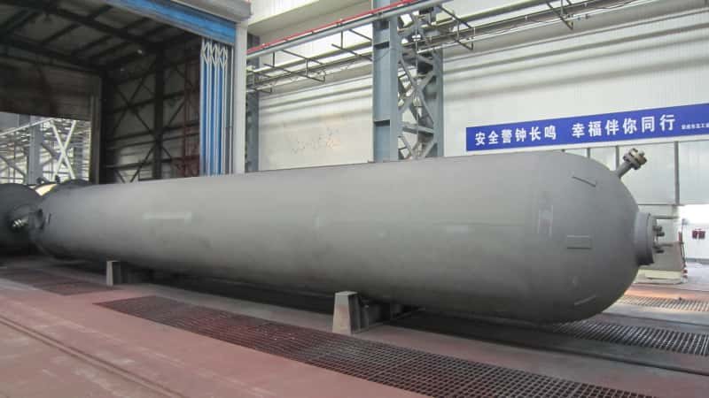
Procurement teams buying into a propane dehydrogenation unit for the first time routinely underestimate how differently PDH equipment behaves compared to standard refinery or petrochemical kit. Reactors cycling between 580 and 650°C, catalyst regeneration systems swinging through repeated oxidation-reduction atmospheres, cryogenic cold boxes operating alongside near-atmospheric reactors on the same plot — the thermal and mechanical fatigue demands are punishing. Miss a material specification in the reactor effluent train or accept a heat exchanger with insufficient creep allowance, and you are looking at unplanned shutdowns within the first two or three operating years, refractory replacement campaigns that run weeks, and propylene-off-spec events that cascade directly into offtake contract penalties.
EPC buyers reviewing PDH plant equipment should prioritize six categories before issuing RFQs: fired heaters and reactor vessels rated for 580–650°C cyclic service, catalyst regeneration system components with oxidation-resistant alloys, reactor effluent heat exchangers designed for coking and fouling margins, cryogenic separation cold boxes, propylene-propane splitter columns, and all interconnecting high-temperature piping — each requiring technology-licensor-specific design envelopes and independent material traceability.
What makes PDH procurement genuinely difficult is that no two licensed processes ask for identical equipment. Honeywell UOP’s Oleflex runs continuous moving-bed reactors with CCR-style regeneration; Lummus Catofin uses fixed-bed reactors with parallel swing operation cycling every 15–25 minutes; ThyssenKrupp’s STAR Process introduces steam and operates at somewhat different pressure profiles. The equipment a vessel fabricator qualifies for one licensor’s train may not transfer cleanly to another’s. That distinction is where most EPC procurement errors originate — and it is exactly what this article works through, system by system.
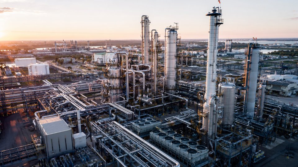
PDH Process Flow and Equipment Inventory: Mapping Every Major Unit to Its Procurement Risk Level
Understanding where the money — and the risk — actually lives in a PDH plant requires walking the process sequence from feed inlet to propylene rundown, not treating the entire equipment list as a uniform procurement exercise. The failure mode for most EPC buyers isn’t missing a vessel; it’s misclassifying a vessel’s criticality and then discovering the error six months into fabrication.
Feed Pretreatment Section
Propane feed arrives with varying contaminant profiles depending on whether the source is a fractionation unit, an LPG import terminal, or a pipeline. Sulfur removal, drying, and sometimes mercury guard beds constitute this section. Equipment here — adsorber vessels, regeneration gas heaters, knockout drums — is largely carbon or low-alloy steel and carries standard lead times of 12–20 weeks for most fabricators. Procurement risk: medium to standard, driven mainly by adsorbent specification alignment and whether the licensor mandates a proprietary guard bed design.
Reactor and Regenerator System
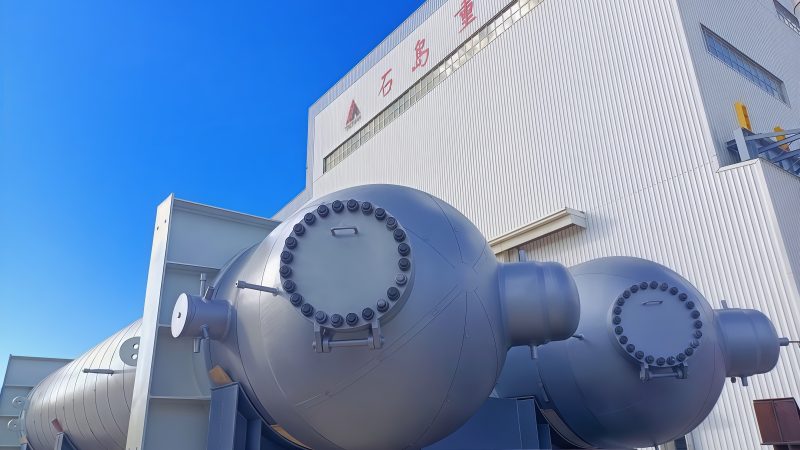
This is where the procurement risk concentrates. Fixed-bed reactors (Catofin uses a bank of adiabatic, cyclically operated vessels) and moving-bed reactors (Oleflex uses a continuous catalyst regeneration stacked-reactor configuration) impose completely different fabrication demands. Operating temperatures of 580–650°C, combined with hydrogen partial pressures and cyclic thermal loading, push material requirements toward 1.25Cr–0.5Mo or higher alloy grades, often with stringent post-weld heat treatment, impact testing at low temperatures for startup cases, and PWHT verification by third-party inspection.
Reactor vessel wall thicknesses can reach 80–140 mm depending on diameter and operating pressure; machining tolerances on catalyst-bed support structures are tight. Lead times for reactor shells alone typically run 40–65 weeks from order placement to ex-works, depending on plate rolling capacity at the fabricator and whether nozzle forgings are procured separately. Procurement risk: high across the board.
Regeneration vessels, used to burn coke off the catalyst, add a further complication: refractory lining design is licensor-specific, and some licensors require witness hold points at lining installation that are incompatible with compressed schedules.
Combined Feed/Effluent Exchangers
CFE exchangers sit between the reactor outlet and the separation train, recovering heat from hot reactor effluent to preheat feed. The thermal duty, temperature cross, and risk of coking on the hot side make these among the most specification-sensitive heat exchangers in the plant. Many configurations use spiral-wound or hairpin designs rather than conventional shell-and-tube, and the tube metallurgy mirrors the reactor: 321 SS or Alloy 800H in some services. Procurement risk: high; do not lump these into a general heat exchanger package RFQ.
Product Separation Train and Cold Box or PSA Units
Reactor effluent contains propylene, unreacted propane, hydrogen, light ends, and trace methane. Separation begins with a series of compressors and knockout drums, then routes to either a cold box (cryogenic separation, common in Oleflex configurations) or a PSA unit (pressure swing adsorption, more common in Catofin) for hydrogen recovery. Cold boxes involve brazed aluminum heat exchangers and plate-fin technology that only a handful of fabricators worldwide can supply — lead times of 60–80 weeks are realistic, and this single equipment item is frequently the schedule driver for the entire project. Procurement risk: high, and often the long-lead anchor.
Depropanizer and Propylene Splitter Columns
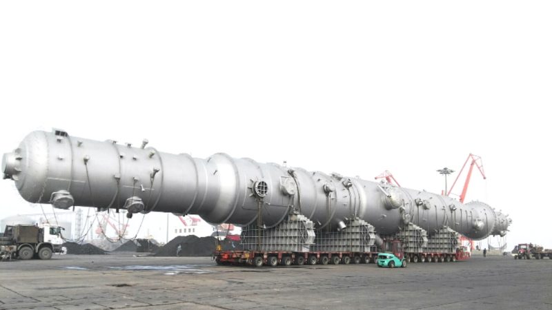
The propylene splitter deserves special attention. Propylene/propane separation requires a large number of theoretical stages — typically 150–200 trays or the equivalent in structured packing — because the relative volatility between propylene and propane is very low (around 1.1–1.15 depending on pressure). This translates into tall, large-diameter columns, often 70–100 meters tall at world-scale capacity, that require strict verticality during transport and erection. High-efficiency tray or structured packing specification, distributor design, and pressure drop tolerance all feed back into product purity, so the column and its internals must be procured as a coordinated package, not split between two vendors to save cost. Procurement risk: high for the splitter; medium for the depropanizer.
The propylene splitter column is typically the largest single pressure vessel by height in a PDH plant, driven by the low relative volatility of the propylene/propane system.True
Propylene/propane relative volatility of approximately 1.1–1.15 requires a very high number of separation stages, which translates directly into column height. This is a well-established separation engineering constraint documented in distillation design references and consistently reflected in actual PDH plant layouts.
Reference Equipment Count by PDH Technology
The table below gives indicative scope ranges. Actual counts depend on plant capacity, whether spare equipment is included, and how the licensor packages proprietary items.
| Equipment Category | Oleflex (UOP) | Catofin (Lummus) | STAR Process (ThyssenKrupp) | Risk Tier |
|---|---|---|---|---|
| Reactor vessels | 3–4 stacked stages | 5–8 individual reactors | 4–6 tubular reactors | High |
| Regenerator / CCR vessel | 1 continuous regenerator | 1 per reactor (swing) | Integrated with reactor | High |
| CFE / process-process exchangers | 6–12 | 8–15 | 6–10 | High |
| Cold box (brazed Al, plate-fin) | Yes — 1 primary unit | Rarely | Varies by design | High |
| PSA units | Optional | Yes — 1–3 beds | Optional | High |
| Depropanizer column | 1 | 1 | 1 | Medium |
| Propylene splitter column | 1–2 | 1–2 | 1–2 | High |
| Feed pretreatment vessels | 4–8 | 4–8 | 4–8 | Standard–Medium |
| Total major pressure equipment | ~200–320 items | ~220–370 items | ~180–300 items | — |
Buyers switching licensor mid-project — not uncommon when a technology license deal changes during FEED — should run a delta analysis against this table immediately. A move from Catofin to Oleflex, for example, eliminates the swing-bed regenerator bank but introduces the continuous CCR vessel and a cold box that Catofin projects often avoid. That is not a minor revision; it is a different procurement campaign.
Reactor and Regenerator Vessel Specifications: Material Grades, Refractory Lining, and Cyclic Duty Qualification
The reactor and regenerator vessels sit at the top of the PDH procurement risk hierarchy. Get the specification wrong here and you are not looking at a maintenance problem — you are looking at a forced shutdown, a refractory rebuild, or a vessel condemned before its design life is half spent. Buyers writing RFQs for these items need to go well beyond standard pressure vessel datasheets.
Material Selection and Nelson Curve Compliance
Reactor shells operating in the 600–650°C range in continuous hydrogen partial-pressure service face simultaneous high-temperature hydrogen attack (HTHA) and creep. The API 941 Nelson curves are not optional guidance — they are the minimum screening tool. For hydrogen partial pressures typical of PDH service (roughly 0.05–0.3 MPa H₂ depending on process configuration and sweep gas rates), 1.25Cr-0.5Mo and 2.25Cr-1Mo alloys sit safely above the carbon steel limit on the Nelson curve, but the margin shrinks as temperature climbs toward 640°C. Some Oleflex reactor configurations push toward 347H austenitic stainless steel for internal components or full shell sections where wall temperatures are highest. Specifying “alloy steel” in an RFQ without pinning the exact UNS designation and the corresponding Nelson curve operating point is a gap that fabricators will exploit — typically by quoting the cheapest compliant material.
2.25Cr-1Mo (P22) is always sufficient for PDH reactor shells up to 650°CFalse
Adequacy depends on hydrogen partial pressure, not temperature alone. At elevated H₂ partial pressures near the upper PDH operating range, 2.25Cr-1Mo may approach its Nelson curve limit. Site-specific process data, not a generic rule, must drive the selection.
Corrosion allowance basis is equally often undefined. Sulfur traces in propane feed, even at low ppm levels, contribute to sulfidation at these temperatures. A corrosion allowance of 1.5–3 mm is common, but the basis — feed composition, expected run length between shutdowns, inspection interval — should be stated explicitly in the specification, not left to the fabricator’s judgment.
Refractory Lining: More Than a Hot-Face Detail
Refractory design in PDH reactors and regenerators is not a liner contractor afterthought. It directly governs shell wall temperature, nozzle stress, and vessel wall thickness. Dense castable refractories (typically 70–90% Al₂O₃, bulk density 2,400–2,800 kg/m³) are common for regenerator duty where rapid thermal cycling during coke burn-off is severe. Firebrick configurations offer superior long-term dimensional stability but demand precise mortar joint control and are sensitive to installation quality in ways that are nearly impossible to verify after enclosure.
Anchor density — typically 18–35 anchors per square meter for high-cycle regenerator walls, depending on lining thickness and thermal shock class — must be specified in the vessel drawing package, not delegated to the refractory subcontractor. Anchor material, usually 310 stainless or Alloy 800H, needs separate qualification. A vessel with a correct steel shell and an under-anchored or wrong-alloy anchor system will delaminate within one to three years in regenerator service.
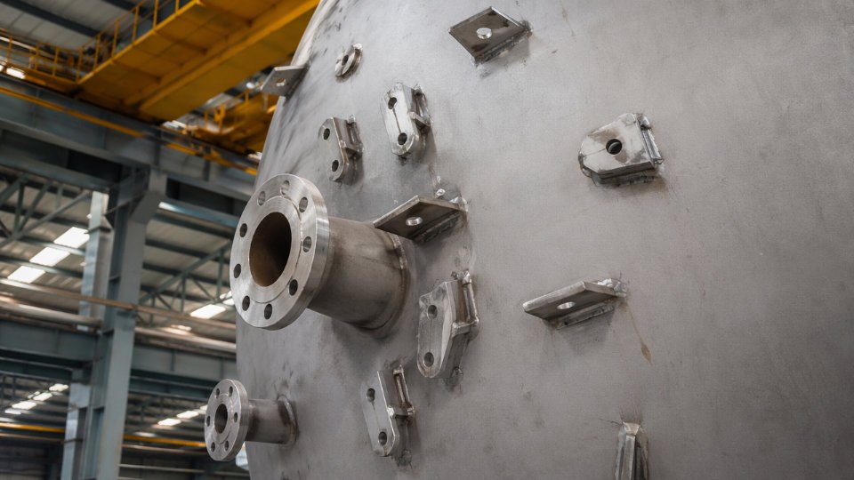
Nozzle detailing through refractory-lined walls requires specific hot-box calculations. Buyers frequently receive vessel drawings where the nozzle reinforcement stops at the cold shell face without accounting for differential thermal expansion at the lining-to-nozzle interface. This is a fabrication error that inspection alone will not catch unless the purchase specification explicitly requires hot-box drawing submissions for review.
Cyclic Duty: Oleflex vs. Catofin Fatigue Profiles Are Not Interchangeable
Moving-bed reactors (Oleflex) run essentially continuous at near-steady thermal conditions. The primary fatigue driver is start-up and shutdown cycles, typically 4–12 thermal cycles per year depending on turnaround frequency. Fixed-bed swing reactors (Catofin) cycle between reaction and regeneration on a 15–30 minute period. That means a vessel in Catofin service may accumulate 15,000–20,000 significant pressure-temperature cycles over a 20-year life. ASME VIII Division 2 or EN 13445 fatigue analysis is mandatory for these vessels, not optional. Weld joint examination category requirements shift accordingly — full radiographic or phased-array UT on all Category A and B seams is the floor, not a premium add-on.
Specifying fatigue life assessment in a Catofin regenerator RFQ without supplying the actual cycle profile — peak temperature, temperature swing magnitude, ramp rates, and hold times — makes the analysis impossible to perform honestly. Fabricators who respond with a price under those conditions are either omitting the analysis or guessing at the inputs.
Fabricator Qualification: What Documentation to Require
Minimum acceptable fabricator qualifications for these vessels should be written into the RFQ, not left to post-bid negotiation.
| Qualification Item | Minimum Requirement | Why It Matters |
|---|---|---|
| Pressure vessel certification | ASME U-stamp, PED Cat III/IV, or GB 150 with third-party inspection | Jurisdiction and export compliance |
| Hot hydrogen service experience | Documented references, at least 2–3 comparable vessels with operating history | Nelson curve application competence |
| PWHT capability | In-house or subcontracted furnace with calibrated thermocouple records | Hardness control in Cr-Mo weldments |
| Hardness testing records | Weld and HAZ hardness survey, 100% of longitudinal and circumferential seams | Prevents PWHT shortcuts |
| Refractory installation procedure | Written dry-out curve, hold points, and signed completion records | Prevents thermal shock cracking on first heat-up |
The dry-out procedure requirement deserves emphasis. Castable refractories contain significant free and chemically bound moisture. A forced or too-rapid dry-out — often driven by commissioning schedule pressure — generates steam pockets that crack the lining before the unit has processed a single barrel of feed. Requiring a signed, witnessed dry-out record as a hold point in the inspection test plan closes that gap.
Combined Feed/Effluent Heat Exchangers and High-Temperature Exchanger Trains: Selection Criteria and Vendor Assessment
The combined feed/effluent exchanger — referred to throughout PDH projects as the CFE — sits at a thermal crossroads that few other process exchangers in petrochemical service match. Hot reactor effluent at 550–620°C (the exact range depending on technology licensor and catalyst cycle stage) gives up heat to cold propane feed entering at roughly ambient to 80°C, recovering energy that would otherwise require furnace duty. That sounds straightforward until you account for the simultaneous demands: steep temperature differentials across the bundle, near-atmospheric to low pressures on both sides, and a process stream carrying trace coke precursors and light olefins that foul progressively over operating cycles.
Thermal Expansion and Configuration Trade-offs
Fixed tubesheet construction is the lowest-cost option and the one most often proposed by budget-minded vendors in early procurement rounds. Avoid it here. The shell-side to tube-side temperature differential in CFE service can exceed 200°C during startup transients and regeneration cycles, generating differential thermal expansion that fixed tubesheets simply cannot accommodate without imposing unacceptable nozzle loads or shell buckling risk. U-tube bundles eliminate the floating-end problem but create dead legs at the bend zone where coke deposition concentrates — a maintenance headache on units with 60–90 day catalyst cycle lengths. Floating head designs (TEMA type AES or AET) are the workable compromise for most world-scale PDH CFE applications: they handle expansion, allow bundle pull for cleaning, and can be designed with anti-bypass sealing strips to preserve thermal efficiency over the bundle’s service life.
Shell diameter on a 500,000–750,000 MT/year propylene unit CFE typically ranges from 1,200 mm to 2,200 mm, with multiple shells in series or parallel depending on total duty and allowable pressure drop. Any design that consumes more than 15–25 kPa on the effluent side warrants challenge — downstream compression and separation equipment is sensitive to feed pressure.
Tube Material Selection and Creep Considerations
The hot-side tube material decision is where procurement documents most often under-specify. Carbon steel and even standard 304/316 stainless become inadequate above roughly 540°C in sustained service; 347H stainless steel is the practical starting point for moderate-temperature hot-side tubes, offering stabilized carbide chemistry that resists sensitization. For the highest-temperature zones or extended design lives beyond 100,000 hours, Incoloy 800H provides superior creep rupture strength — but it carries a significant material cost premium (Incoloy 800H tube pricing runs 4–8× equivalent 347H, depending on diameter, wall, and market conditions) and demands qualified welding procedures that not every fabricator actually has in verified production, as opposed to on paper.
Incoloy 800H has demonstrably better creep rupture life than 347H SS at temperatures above 600°CTrue
Published creep rupture data from ASME Section II Part D and materials testing literature confirms Incoloy 800H retains higher stress-to-rupture values at 600°C+ compared to 347H stainless steel, making it appropriate for the most thermally demanding PDH exchanger tube applications.
Design life calculations should reference ASME Section VIII Division 1 with ASME Code Case 2328 or equivalent for alloy tubes, and the vendor’s weld procedure qualification records (WPS/PQR) must explicitly cover the tube-to-tubesheet joint in the proposed alloy — not a surrogate material. Creep damage accumulates fastest during hot startups; if the plant anticipates more than 40–50 thermal cycles per year, that cycle count needs to appear in the design basis document sent to vendors at RFQ stage.
Inspection and Testing Requirements
TEMA Class R is the baseline for PDH CFE service, but it is a floor, not a ceiling. Tube-to-tubesheet joints in high-alloy service warrant full weld procedure qualification per ASME Section IX with destructive mock-up testing before production fabrication begins. Radiographic examination of tubesheet welds and shell course seams should be 100% RT, not spot. Helium leak testing of the completed bundle — rather than hydrostatic test alone — detects micro-leaks at tube-to-tubesheet joints that hydro pressure will mask; a cross-contamination leak between feed and effluent in CFE service compromises reactor selectivity and shows up as yield loss that takes weeks to diagnose correctly.
Vendor Evaluation Checklist
A vendor’s proposal price means little without confirming operational capability. Run through these points during technical bid evaluation:
| Evaluation Item | Minimum Acceptable | Red Flag |
|---|---|---|
| In-house tube rolling and seal-weld capability | Demonstrated for alloy specified | Subcontracted with no QC oversight |
| Alloy exchanger reference list | 3+ similar services in past 7 years | References in carbon steel only |
| WPS/PQR for proposed tube-to-tubesheet joint | Alloy-specific, current, with test records | Generic procedure, no mock-up data |
| Delivery schedule basis | Firm material lead times from mills | Schedule built on assumed stock |
| Spares package inclusion | Tube bundle spare quoted with unit | Spares deferred to separate contract |
Delivery is consistently where CFE procurement goes wrong on compressed EPC schedules. High-alloy tube procurement alone — particularly for Incoloy 800H in heavy-wall, small-diameter configurations — carries lead times of 20–36 weeks from specialty mills, and that clock starts only after mill order placement, not after contract signature. Any vendor quoting 14–16 weeks total fabrication for a large-diameter, high-alloy CFE bundle without showing confirmed mill slots is presenting a schedule that will slip. Push for mill order confirmation as a contractual milestone tied to payment.
Separation Train Equipment: Depropanizer, Propylene Splitter, and Hydrogen Recovery Unit Procurement Checkpoints
The separation section of a PDH plant gets underestimated in early procurement planning more often than almost any other area. Engineers familiar with conventional refinery fractionation sometimes treat these columns as catalogue items. They are not. Trace contaminants from the dehydrogenation reaction, tight polymer-grade purity targets, and cryogenic conditions in hydrogen recovery combine to create specification demands that will expose any gap between a fabricator’s sales capability and their actual engineering depth.
Depropanizer Column: More Than a Routine Fractionator
The depropanizer separates C3 components from C4+ heavies, typically operating at 10–18 bar depending on condenser cooling medium (propylene refrigerant vs. cooling water) and the specific process licensor configuration. That pressure range matters when selecting internals. Structured packing offers lower pressure drop and better turndown flexibility — useful when a plant operates below nameplate capacity during startup or market-driven rate reductions — but it carries a meaningful height and cost premium and is more vulnerable to fouling if upstream knockout performance degrades. Valve trays or fixed valve trays give more robust hydraulic turndown and are easier to inspect, but the column ends up taller with higher pressure drop, which feeds back into reboiler duty and utility consumption.
The right choice depends on how stable the feed composition is expected to be across the plant’s operating envelope and how seriously the owner values turndown flexibility. Buyers should require the vendor to submit hydraulic rating summaries at 60%, 80%, and 100% of design feed rate — not just the design-point calculation.
Propylene Splitter: The Tallest Vessel on the Battery Limit
The propylene splitter routinely demands 100–180 theoretical stages to reach polymer-grade propylene at 99.5 mol% purity or better, which translates to a column that is frequently the tallest structure on site. Heights of 80–120 meters are not unusual for large-scale units, sometimes split into two mechanically separate shells with a liquid connector to manage transportation and erection constraints.
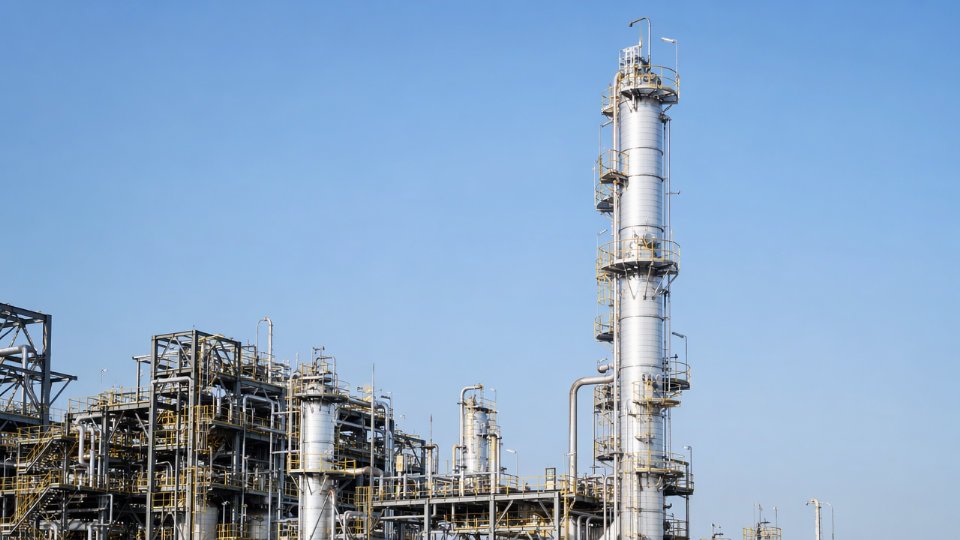
Tray efficiency data here is not a minor detail. A 3–5% deviation in assumed tray efficiency propagates into either a purity shortfall or a taller, more expensive column than budgeted. Buyers should demand that the column vendor provide detailed hydraulic rating reports with documented tray efficiency basis — whether derived from licensor proprietary correlations, published Fair-type methods, or vendor test data. Anti-fouling internals are worth specifying explicitly: polymer precursors can deposit on trays over time, degrading efficiency and eventually forcing unplanned shutdowns. Specify maximum fouling factors and require the vendor to confirm their tray design accounts for them.
Polymer-grade propylene from a PDH splitter requires minimum 99.5 mol% propylene purity.True
This is the standard commercial specification for polymer-grade propylene used in polypropylene production, widely confirmed across industry licensor documentation and product sales standards.
Hydrogen Recovery Unit: Equipment Scope Varies Dramatically by Technology
PSA, membrane separation, and cold box cryogenic recovery each bring a fundamentally different equipment list into your procurement scope. PSA systems require multiple adsorber vessels — typically carbon molecular sieve or zeolite-based — rated for pressure cycling duty, commonly 20–35 bar operating pressure with cycle times of 60–300 seconds. Vessel fatigue classification and weld inspection requirements should reflect cyclic service explicitly in the fabrication spec, not just static pressure vessel rules.
Membrane systems replace adsorber vessels with module housings, but those housings still require careful pressure and permeation testing documentation, and the membrane modules themselves are proprietary supply items with long lead times — sometimes 16–24 weeks from specialized suppliers.
Cold box units bring brazed aluminum heat exchangers into scope, operating at temperatures potentially reaching –100°C or lower. These demand full impact testing per MDMT, Charpy V-notch test documentation at the minimum design metal temperature for P1 and P4 material groups, and PWHT records where wall thickness triggers code requirements. Do not accept a cold box vendor’s material test reports without confirming the impact test temperature matches your calculated MDMT with margin, not just the code minimum.
Procurement Documents That Must Be in Your RFQ Response Package
For every major separation train item, the following should be non-negotiable in vendor submittals: process datasheet stamped by the licensor or process design contractor; hydraulic calculation summary at multiple operating rates; tray or packing sub-vendor identity and their fabrication and inspection standards; pressure test certificates with test medium, duration, and witnessed inspection records; and for cold service equipment, a complete low-temperature material certification package traceable to heat numbers. Accepting a vendor’s word that “all documentation will follow” has a direct path to commissioning delays when certificates are missing at mechanical completion.
Pressure Vessel and Column Fabrication Standards: Navigating ASME, PED, GB 150, and Project-Specific Code Conflicts
International PDH projects routinely land EPC buyers in a frustrating position: three vendors submit proposals citing three different design codes, and the buyer’s engineering team must decide whether those proposals are genuinely equivalent or whether one of them has quietly traded safety margin for a lower price. Getting this wrong doesn’t surface at bid stage — it surfaces during statutory inspection, at port of entry, or when a weld fails under cyclic thermal loading in year two.
How ASME, EN 13445, and GB 150 Actually Differ in Practice
ASME Section VIII Division 1 uses a design factor of 3.5 on tensile strength for most vessels, while Division 2 drops that factor to 3.0 but requires a more rigorous stress analysis and a mandatory design review. For PDH reactor and regenerator vessels operating at 580–650°C with cyclic pressure swings during regeneration sequences, the higher analytical discipline of Div. 2 is usually the correct choice even if the nominal design pressure sits below the threshold where Div. 2 becomes mandatory. Specify it explicitly; don’t leave the vendor to choose.
EN 13445 under PED 2014/68/EU takes a different route. It applies a design factor that depends on material category and inspection class, and it integrates conformity assessment procedures — Module G for one-off custom vessels is common in PDH service — into the fabrication scope itself. The Notified Body is not just a stamp at the end; it participates in design review and material certification at defined stages. Buyers targeting European installation sites who specify ASME without a derogation process from the competent authority are creating a legal compliance gap, not just a paperwork problem.
GB 150 (pressure vessel) and GB 151 (heat exchangers) govern China-domestic fabrication. The design margins align reasonably closely with ASME Div. 1 for standard carbon and low-alloy steel, but diverge meaningfully for high-alloy and refractory-clad vessels typical of PDH service. GB 150 uses Chinese material standards — such as 15CrMoR and 12Cr2Mo1R — that require documented cross-reference to ASME or EN equivalents before a dual-code data book can be accepted. That cross-reference work takes time and requires material manufacturer mill certificates that explicitly list both standard designations.
When Equivalency Arguments Work and When They Don’t
Code equivalency is defensible for vessels destined for jurisdictions without statutory registration requirements, provided the buyer documents the comparison formally in the equipment requisition. For vessels that will be registered with a national inspection authority — common in the EU, South Korea, Japan, and increasingly in Southeast Asian markets — the local authority makes the final call, and “equivalent to ASME” is not a substitute for the required marking and documentation trail. Dual-code fabrication, where the vessel is designed and documented to satisfy both the project-specified code and the installation-country statutory code simultaneously, adds roughly 8–15% to fabrication cost depending on the material and complexity, but it eliminates re-inspection risk at installation.
Writing an ITP That Protects the Buyer
Third-party inspection scope for high-temperature, cyclic-duty PDH vessels should distinguish clearly between HOLD points — fabrication cannot proceed without TPI physical attendance and sign-off — and WITNESS points, where the TPI is notified and attends if available but work can proceed after a defined waiting window. REVIEW points cover document checks only. For PDH service, HOLD points should appear at minimum at: raw material receiving and positive material identification (PMI) completion, fit-up and dimensional inspection before welding begins, post-weld heat treatment (PWHT) chart review and hardness testing, and final hydrostatic or pneumatic test. Leaving any of these as WITNESS rather than HOLD is a risk acceptance decision, not a schedule optimization.
NDE Acceptance Criteria: Standardize Before RFQ, Not After
Radiographic testing acceptance criteria under ASME VIII Div. 1 (UW-51 for full RT, UW-52 for spot) differ from EN 13445 Annex G and from NB/T 47013 used in the GB framework. A vessel fabricated to GB 150 with NDE performed to NB/T 47013 Level II may not meet the ASME RT acceptance criteria for the same weld joint efficiency assumption. The equipment requisition must specify the exact NDE standard, acceptance level, and the required weld joint efficiency by joint category — don’t leave this to the fabricator’s QC plan. For alloy-steel components above 450°C service, requiring 100% RT plus supplemental UT for all full-penetration butt welds is standard practice on well-run PDH projects, regardless of which base code governs.
A vessel carrying a U-stamp nameplate is automatically compliant with PED requirements for EU installation.False
ASME U-stamp and PED CE marking under EN 13445 are independent conformity frameworks. A U-stamped vessel requires a separate conformity assessment by a Notified Body and must carry CE marking with a Declaration of Conformity to be legally placed on the market in the EU. The U-stamp alone does not satisfy PED statutory requirements.
Documentation Packages: What the Final Data Book Must Contain
A complete data book for an export PDH pressure vessel should include: full material traceability from mill certificate to final component (MTR chain with heat and lot numbers), all NDE reports with film or digital image archive, PWHT time-temperature charts with calibrated recorder certificates, hydrostatic test records, dimensional inspection reports, and the final as-built drawing set. For U-stamped vessels, the Manufacturer’s Data Report (Form U-1 or U-1A) is not optional — it is the legal record. For CE-marked equipment, the Technical File and Declaration of Conformity must be retained by the manufacturer for at least ten years post-delivery. Buyers should require the data book index at the time of order, not at shipment, and use it as a milestone payment gate. Receiving a vessel without a complete data book is not an administrative inconvenience; it is an unregisterable asset.
Vendor Pre-Qualification Framework: Technical, Commercial, and Delivery Criteria Specific to PDH Equipment Suppliers
Generic vendor registration templates — the kind that ask for ISO certificates, a company profile PDF, and three reference project names — are nearly useless for PDH equipment procurement. The failure modes in a PDH plant are specific: a reactor vessel that develops creep at a weld seam after 18 months of cyclic thermal loading, a propylene splitter that arrives 14 weeks late because the fabricator underestimated the transport permit lead time, a CFE exchanger with tube-to-tubesheet joints that leak during the first regeneration cycle. Pre-qualification has to be designed to catch those risks before a purchase order is issued, not after first inspection.
Minimum Technical Capability Thresholds by Equipment Category
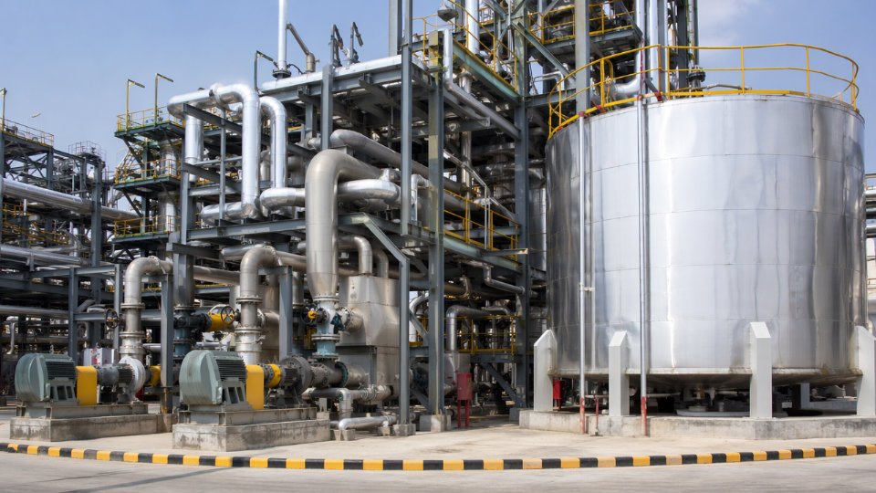
Start with hard capability gates, not weighted scores. A reactor vessel fabricator without documented thick-wall chromium-molybdenum or high-alloy weld procedure qualifications under hydrogen service conditions should not reach the commercial evaluation stage. Ask for the actual WPS/PQR records and the mill certifications on the base plate they used — not a general statement that they “have ASME Section IX experience.” For CFE and high-temperature exchanger shops, require evidence of high-alloy tube bundle assembly: Incoloy 800HT or Alloy 625 overlay cladding records, tube-to-tubesheet weld mock-up inspection reports, and documented helium leak test results. Column fabricators handling a propylene splitter in the 70–90 m height range need a verifiable transport history — specific project records showing coordination with oversized load carriers, wind-load analysis for upright transport, and erection sequence documentation reviewed by a licensed structural engineer.
Financial and Physical Capacity Screening
Workshop floor area, crane capacity, and heat treatment furnace size are not bureaucratic checkboxes. A fabricator with a single 200-tonne overhead crane cannot efficiently handle a reactor vessel shell section that exceeds that weight limit without rigging workarounds that introduce schedule risk and quality exposure. Ask for the current order book utilization, not just installed capacity. A shop running at 85–95% utilization when you plan to place your order will deprioritize your job when a schedule conflict develops. Furnace size matters for post-weld heat treatment of large-diameter nozzle welds; undersized furnaces lead to local PWHT workarounds, which are technically permissible under some codes but carry higher residual stress scatter and should be flagged in your technical review. Cash flow screening — reviewing audited financials for the past two to three years — helps identify fabricators who may accept your advance payment and then divert it to settle earlier project obligations.
Reference Project Verification
Reject vague capability statements. Request specific equipment tag numbers from completed projects, the name and direct contact information of the client’s equipment inspector or project engineer, and as-built inspection dossiers including final hydrostatic test records, NDE summary reports, and PWHT charts. Call the references. A fabricator who built a similar reactor vessel for a comparable PDH or dehydrogenation service five years ago will have an inspector somewhere who remembers the job and can speak to actual execution quality.
Subcontractor and Material Supply Chain Review
The fabricator’s own shop is only part of the story. Forged nozzle suppliers, specialty alloy plate mills, refractory installation subcontractors, and valve interlock system vendors each carry independent schedule and quality risk. Request the fabricator’s nominated subcontractor list and verify that forged nozzle lead times — typically 16–28 weeks depending on alloy grade and wall thickness — are already factored into their delivery schedule. Refractory lining contractors for reactor vessels deserve separate technical assessment; castable lining installation quality depends heavily on the crew’s experience with anchor density, curing protocol, and dryout procedures specific to cyclic service.
Scoring Matrix Structure
A weighted pre-qualification scoring matrix that separates technical capability gates from commercial scoring will consistently outperform a single-score ranking system for complex PDH equipment procurement.True
Binary technical gates eliminate unqualified vendors before commercial criteria introduce price-driven distortions; this two-stage structure is standard practice in major EPC qualification procedures and reduces the risk of awarding to a commercially attractive but technically marginal fabricator.
A practical matrix for PDH equipment pre-qualification should apply hard pass/fail gates first — weld procedure qualification, relevant material experience, code stamp validity — then apply weighted scoring across four domains: technical capability (30–35%), quality system maturity (20–25%), delivery track record (25–30%), and after-sales support including commissioning spares availability (15–20%). The weighting shifts depending on equipment category; delivery track record carries more weight for long-lead columns than for standard pressure vessels where multiple qualified sources exist. Document the scoring rationale for each vendor so that late-stage commercial negotiations do not silently override technical findings.
Lead Time, Logistics, and Modular Fabrication Considerations That EPC Schedulers Must Embed in Equipment Contracts
Schedule failures in PDH projects rarely originate on the construction site. They originate months earlier, in procurement documents that treat fabrication lead times as negotiable and logistics planning as something to handle after award. By the time that assumption is tested, the critical path has already slipped.
Realistic Fabrication Lead Times by Equipment Category
Large reactor and regenerator vessels — the high-alloy, refractory-lined pressure vessels operating at 580–650°C under cyclic thermal duty — typically require 12–20 months from purchase order to ex-works delivery. The range depends on material availability for Incoloy or high-chrome alloys, shop queue position at qualified heavy fabricators, and the number of inspection hold points the owner’s engineer enforces. Don’t compress this estimate without written confirmation from the specific shop.
Propylene splitter columns are consistently the longest-lead item in the separation train: 14–22 months is a realistic range for world-scale units, driven by the combination of large diameter (often 5–8 meters), tall height (80–120 meters in some configurations), and the number of high-precision valve or structured packing stages that require staged internal inspection. Column shells are fabricated in sections and field-welded, but shop sub-assembly quality directly affects site erection speed.
High-alloy combined feed/effluent exchangers and other high-temperature exchanger trains typically fall in the 10–16 month range, with the upper end applying when proprietary tube bundle geometries require licensor-directed manufacturing oversight or special weld procedure qualifications.
PSA adsorber vessels for hydrogen recovery are somewhat more standardized but still demand 8–14 months, particularly when the molecular sieve loading, vessel internals, and automated valve skids are contracted as an integrated package rather than separated across multiple suppliers.
Critical Path Awareness: What Gets Awarded First
The propylene splitter column and the CFE exchanger trains are almost always the equipment delivery critical path in a PDH project. Award them last and you will compress construction float to zero before the first concrete pour is finished. EPC schedulers should target issuing technical packages for these two items within 60–90 days of project sanction — well before P&IDs are fully frozen — and align award timing with the overall project schedule float analysis, not with procurement department workload.
A practical rule: if awarding the propylene splitter is waiting on final tray count confirmation, issue a letter of intent based on shell and nozzle dimensions and manage the internal scope with a defined change order mechanism. Holding full award for complete documentation will cost more than the change order ever will.
Heavy Lift and Abnormal Transport Planning
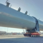
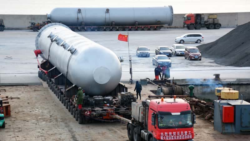
Tall columns and large reactor vessels routinely exceed the dimension and weight envelopes that permit standard road or barge movement without special authorization. In many jurisdictions, loads above roughly 80–150 tonnes gross weight or exceeding about 4.5–5 meters in any cross-section trigger abnormal transport permits, route surveys, escort requirements, and sometimes bridge load assessments. The specific thresholds vary by country and even by province or state, so route planning must start during detailed engineering — not at shipping time.
Port handling capability is equally consequential. A fabrication yard located near a deep-water berth with a 500-tonne gantry crane gives you options that an inland shop does not. When evaluating fabricator bids for oversized columns, port access and rigging capability should carry explicit weight in the technical evaluation matrix.
Module yard layout design must account for these envelopes from day one. A column that arrives at the module yard and cannot be positioned without dismantling temporary structures has already consumed schedule buffer that probably didn’t exist.
Modular vs. Stick-Built Strategies for Remote Locations
For PDH plants built at sites with limited skilled labor supply, poor road infrastructure, or compressed onsite construction windows, modular pre-assembly in a fabrication yard reduces site execution risk substantially. Piping-intensive utility modules, heat exchanger skids, and compressor packages are strong candidates for modular delivery. Tall columns and large pressure vessels are generally stick-built at site due to transport constraints, though their supporting structure and interconnecting piping can be pre-assembled modularly.
The inspection boundary matters here. Any equipment that will be enclosed in a module frame — meaning post-enclosure inspection access is limited — must reach full hold-point clearance before frame closure. EPC contracts should define this explicitly as a contractual milestone, not an informal shop understanding.
Completing all mandatory inspection hold points before module frame enclosure is required practice under most major inspection codes and is not optional regardless of schedule pressure.True
ASME, EN, and equivalent codes require documented inspection access at defined stages; enclosing equipment before those records are closed creates code compliance risk and potential rework costs that dwarf any schedule saving.
Contract Clauses That Protect Schedule and Quality
Milestone-linked payment tied to verified inspection hold points — not just calendar dates — gives the buyer genuine leverage. Structure payments around events like shell course completion with dimensional records, heat treatment with documented curves, and pre-shipment hydrostatic test, rather than around elapsed time since order.
Liquidated damages for delivery delay are standard but are often written with caps so low they provide no real deterrent. Set LD rates at a level that reflects actual project delay costs — daily standby costs for site labor and crane hire run across a wide range depending on project scale and location, but they are always higher than a nominal LD rate.
Preservation and packing standards for long-distance sea freight deserve their own contract exhibit. Internal corrosion during a six-month ocean transit has compromised more than one expensive alloy exchanger bundle. Specify desiccant type and quantity, nitrogen blanketing requirements where applicable, inspection of packing before container sealing, and photographic documentation as a condition of final payment release.
Frequently Asked Questions: PDH Plant Equipment Procurement for EPC Buyers

What is the most commonly under-specified piece of equipment in a PDH plant procurement package?
The combined feed/effluent (CFE) exchanger consistently arrives at fabricators with incomplete specifications. Buyers focus on steady-state heat duty and material grade, then omit the cyclic thermal duty profile — the exchanger sees repeated heating and cooling cycles tied to catalyst regeneration, and without a documented thermal fatigue basis, vendors cannot size expansion provisions or select the right tube-to-tubesheet joint configuration. Creep allowance basis is another gap: at metal temperatures that can approach 550–620°C depending on train configuration, design-life creep damage must be accounted for in tube thickness and header design, not treated as a safety-factor afterthought. When these details are absent from the RFQ package, you either receive non-compliant bids that look attractively priced or you discover the gap during detail engineering review — typically triggering change orders that cost more in schedule than in material.
Can a fabricator certified only to GB 150 supply equipment for a PDH plant in the Middle East or Europe?
Not without additional steps, and the answer depends entirely on the installation country’s statutory framework. A vessel fabricated to GB 150 and destined for an EU installation falls under the Pressure Equipment Directive (PED 2014/68/EU), which requires conformity assessment by a Notified Body — GB 150 certification alone does not satisfy this. For projects in Saudi Arabia or the UAE, the local authority having jurisdiction (AHJ) often accepts ASME U-stamp or PED CE-marking as the baseline; GB 150 alone is rarely accepted without supplementary documentation or third-party re-certification. Dual-code fabrication — where a shop holds both GB 150 registration and ASME U-stamp authorization — is a workable solution but adds 8–15% to fabrication cost and requires the shop to maintain a qualifying quality management system under both regimes.
GB 150 certification is automatically equivalent to ASME Section VIII Div.1 for pressure vessel export purposes.False
GB 150 and ASME Section VIII use different design methodologies, allowable stress bases, and inspection protocols. Equivalency must be demonstrated through a formal code comparison and accepted by the installation country's AHJ or Notified Body. It is never automatic.
EPC buyers should define statutory requirements for the installation country before issuing any RFQ, not after bids are returned.
How many spare equipment items should a PDH plant procurement package include?
Typical PDH spare packages include one complete reactor internals set per reactor train, full replacement tube bundles for the CFE exchangers, and a two-year consumables and instrumentation spares list covering control valves, transmitters, and refractory anchor hardware. Rotating equipment spares — compressor internals, labyrinth seal kits, dry gas seal cartridges — are normally specified by the rotating equipment discipline separately, with OEM recommendations setting the baseline. Plants in remote locations or regions with long customs lead times should weight the spares package more heavily; a single unplanned shutdown waiting on a replacement tube bundle can erase the procurement savings from a lean spares strategy many times over.
What inspection hold points are non-negotiable for PDH reactor vessels?
For any reactor operating in hot hydrogen service, these hold points cannot be waived: material heat and chemical certification review before any fabrication begins, post-weld heat treatment (PWHT) time-temperature chart witnessing, hardness survey across all weld zones and heat-affected areas, hydrostatic test witnessing at the specified test pressure, and final dimensional and NDE report review before release. Some EPC quality plans also include refractory anchor torque inspection and dry-out curve witnessing before shipment. Hydrogen embrittlement is not a theoretical risk in this service — it is an operational certainty if material and PWHT controls slip during fabrication.
How does the choice of PDH technology licensor affect equipment procurement strategy?
Profoundly, and earlier than most procurement teams expect. Honeywell UOP’s Oleflex process uses moving-bed radial-flow reactors with continuous catalyst regeneration, which demands specialized internals, catalyst transfer lines, and lock-hopper vessels that only licensor-approved fabricators can supply without a lengthy qualification process. Lummus Catofin runs parallel fixed-bed reactors in swing regeneration mode, so the procurement emphasis shifts to identical vessel sets, shared regeneration headers, and high-cycle valve systems. ThyssenKrupp’s STAR process uses a tubular, reformer-style reactor design, bringing heat transfer tube specifications and support systems into focus.
Each licensor issues an Approved Vendor List (AVL) and equipment datasheets that govern which fabricators are pre-qualified and which technical deviations trigger formal licensor review. Attempting to substitute off-AVL vendors without licensor concurrence introduces technology license risk, not just commercial risk. EPC buyers should obtain the licensor’s AVL and datasheet package at the earliest possible stage — ideally during FEED — so procurement lead times reflect the real pool of qualified suppliers, not an optimistic assumption about open competition.