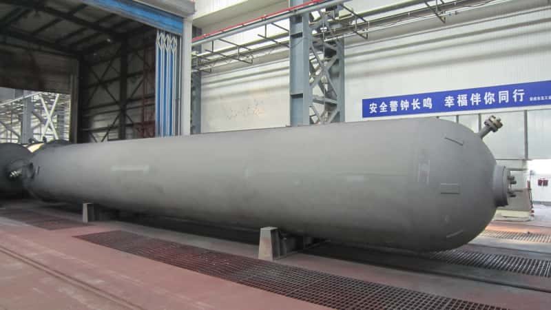

A heat exchanger that’s quietly underperforming doesn’t announce itself with an alarm — it bleeds your operation through rising fuel consumption, missed throughput targets, and process temperatures that drift just enough to force manual compensation. Fouling alone can strip 10–30% of thermal efficiency before anyone on the floor connects the dots, and by the time energy cost overruns hit 15–25% in a refinery setting, the damage is already weeks or months old. Left unaddressed, that degradation path ends in unplanned shutdown — and in a petrochemical or processing plant, unscheduled downtime tied to heat exchanger failure accounts for roughly 5–8% of total annual lost production time. Repair lead times of 6–20 weeks, depending on whether your unit requires ASME U-stamp or PED recertification, turn what looked like a maintenance problem into a capital and scheduling crisis.
A heat exchanger “goes bad” through one of four failure modes: fouling-driven efficiency loss, mechanical tube failure (cracking, pitting, or erosion), gasket or seal degradation causing cross-contamination or external leaks, and structural shell or weld deterioration from corrosion or thermal fatigue. Each mode carries a different detection window, consequence severity, and repair strategy — fouling is gradual and recoverable; a tube rupture in high-pressure service is immediate and potentially catastrophic.
What makes heat exchanger failure genuinely dangerous from a plant management perspective isn’t just the hardware cost — tube bundle replacement runs $15,000 to over $250,000 depending on material grade and geometry, and a full shell-and-tube replacement in high-pressure service can exceed $500,000 installed. It’s that each failure mode mimics something else: a fouled exchanger looks like a process upset, a leaking tube looks like product contamination of unknown origin, and a thermally fatigued shell looks structurally sound right up until it isn’t. Understanding exactly what’s happening, and when, is what separates a planned outage from an emergency.
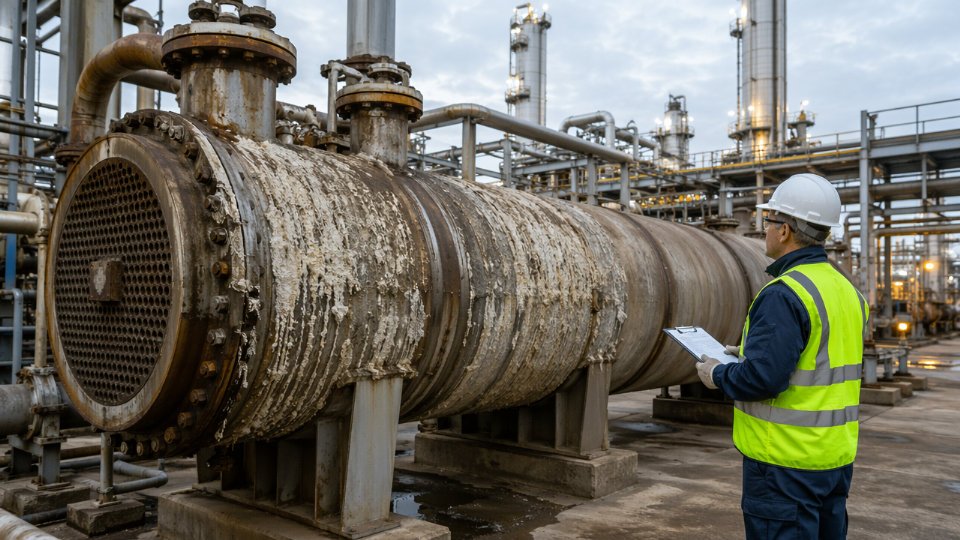
The Seven Measurable Warning Signs That Your Heat Exchanger Is Degrading
Degradation rarely announces itself with a catastrophic bang. It creeps through your process data for weeks — sometimes months — before a tube ruptures or a gasket blows. The engineers who catch it early are the ones watching the right numbers, not waiting for the alarm to trip.
1. LMTD Drift and Declining U-Value in DCS Trend Data
The overall heat transfer coefficient (U-value) is your single most reliable early-warning metric. Plot it weekly against a clean baseline. In shell-and-tube exchangers handling hydrocarbon service, a U-value decline of 15–25% from the post-commissioning baseline typically signals fouling heavy enough to warrant inspection scheduling — the exact threshold depends on your design margin and service criticality. Plate exchangers, with their tighter channel gaps, often show performance penalties at just 10–15% U-value drop because fouling occupies a higher fraction of the effective flow area. Log mean temperature difference (LMTD) drift reinforces the picture: if your target outlet temperature is slipping while feed rate and inlet conditions remain constant, the DCS trend is telling you something the eye cannot see.
2. Unexplained Pressure Drop Increase
A rising delta-P across the tube side or shell side — independent of flow rate changes — is a direct proxy for fouling layer growth or partial blockage. In crude preheat trains, a 20–30% rise in tube-side pressure drop over a run cycle often corresponds to a fouling resistance (Rf) approaching the TEMA design allowance. In cooling water circuits with biological fouling, the same delta-P signal can appear faster, sometimes within 4–8 weeks of inadequate biocide dosing. Track delta-P as a trended ratio against design, not as an absolute number, or seasonal flow changes will mask the signal.
3. Vibration Signatures and Acoustic Emission
Portable vibration analyzers placed on the shell body can detect tube bundle loosening and baffle-to-tube wear before any process parameter shifts. Flow-induced vibration — common in exchangers where the shell-side velocity exceeds the critical threshold for the unsupported tube span — produces a characteristic broadband frequency signature in the 50–300 Hz range. Acoustic emission monitoring is more sensitive still; it can pick up micro-cracking at tube-to-tubesheet joints under thermal cycling long before a detectable leak develops.
4. Visual and Analytical Fluid Indicators
Cross-contamination is sometimes the first hard evidence of tube failure. A sudden pH shift in your cooling water return, a conductivity spike, or process fluid discoloration visible in sight glasses all warrant immediate inline analyzer review and a grab sample to the lab. In steam-heated reboilers, hydrocarbon breakthrough into the condensate is both a safety event and a clear tube-integrity signal. Don’t wait for a routine sample cycle — pull a sample the moment the conductivity transmitter moves unexpectedly.
A single pinhole tube leak in a high-pressure gas cooler can be undetectable by pressure drop monitoring alone for days while cross-contaminating downstream fluid systems.True
Pinhole leaks at differential pressures above roughly 3–5 bar can pass fluid volumes too small to register as meaningful delta-P change while still causing measurable contamination in the lower-pressure stream — a well-documented failure mode in refinery and gas processing services.
5. Utility Consumption Anomalies
If your steam control valve is opening further — or your cooling water flow demand is climbing — to hold the same target outlet temperature with no change in feed rate or composition, the process is compensating for lost thermal duty. A steam consumption increase of 10–20% against a stable production rate is a credible fouling indicator in evaporator and reboiler service. Track utility KPIs per unit of throughput, not in absolute terms, or production rate swings will obscure the trend.
6. Infrared Thermography on the Shell Exterior
A thermal camera scan during normal operation takes under 20 minutes per exchanger and costs almost nothing relative to what it reveals. Hot spots on the shell exterior point to localized flow maldistribution — often caused by baffle bypass, bundle sagging, or inlet nozzle erosion. Cold zones, particularly in vertical thermosiphon reboilers, suggest vapor blanketing or tube bundle partial blockage. Schedule IR scans during planned walk-rounds rather than only during formal turnarounds; the value is in trending, not in a single snapshot.
7. Elevated Metal Ion Content in Fluid Samples
Rising iron, nickel, or chromium concentrations in cooling water or condensate samples — even before any visible leak — indicate active corrosion of tube walls. In admiralty brass or copper-nickel tube bundles handling cooling water, copper ion content above roughly 0.1–0.3 mg/L in the return line often precedes visible pitting by weeks. In carbon steel tube bundles exposed to oxygen-contaminated condensate, iron counts above site-specific thresholds (typically set by your water treatment provider based on system volume and flow rate) warrant an expedited eddy-current inspection rather than waiting for the next scheduled outage. The sample frequency matters: monthly sampling misses fast-developing attack; weekly or continuous online analyzers give you the lead time to act.
Root Cause Breakdown: Why Heat Exchangers Fail in Petrochemical, Refinery, and Chemical Plant Service
Failure investigation gets mishandled when teams treat symptoms—declining outlet temperature, rising differential pressure, tube leak—as root causes. Each of those readings is evidence of an underlying mechanism, and the right corrective action depends entirely on identifying which mechanism is operating. Conflating them leads to repeat failures after the next turnaround.
Fouling Mechanisms and the Process Conditions That Drive Them
Fouling is not a single phenomenon. Particulate fouling—suspended solids, catalyst fines, coke particles—accumulates in low-velocity zones, typically below 0.9–1.2 m/s on the tube side in refinery crude preheat trains. Crystallization fouling dominates in services where cooling water is supersaturated with calcium carbonate or calcium sulfate, and it accelerates sharply above 60–70 °C skin temperature at the tube wall. Biological fouling is a once-through or open recirculating cooling water problem; it rarely gets sufficient attention until a seasonal biocide failure allows biofilm to blanket an entire bundle within days, not weeks.
Corrosion-product fouling—magnetite deposits from carbon steel piping upstream—is common in steam condensate systems and heat recovery trains. Polymerization fouling is specific to services handling unsaturated hydrocarbons, styrene, or reactive monomers; wall temperatures even 10–15 °C above the bulk fluid temperature can initiate localized polymerization that cements deposits onto tube surfaces faster than any cleaning interval can address.
pH excursions, velocity imbalances across a bundle, and oxygen ingress each act as accelerants. A unit running at reduced throughput during a partial-load period may drop tube-side velocity below the design minimum, shifting a previously manageable fouling rate into a regime where deposits compound every week.
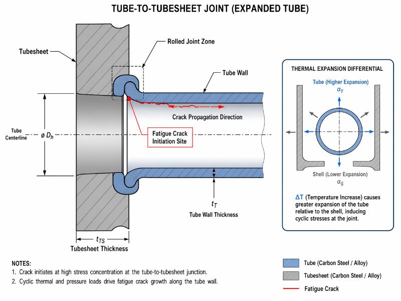
Thermal Fatigue and Cyclic Stress at Tube-to-Tubesheet Joints
Batch chemical reactors and refinery charge heaters see rapid temperature swings—feed preheat can shift 80–120 °C within minutes during a startup or emergency shutdown. Each cycle imposes differential thermal expansion between the tube bundle and the shell. Over 500 to 2,000 cycles (a range that depends on material pairing, cycle amplitude, and joint geometry), the tube-to-tubesheet joint develops fatigue cracking or rolled-joint loosening. Steam hammer—caused by condensate slugging in steam-side exchangers—introduces impact loading that compounds cyclic stress damage faster than thermal cycling alone.
Chloride-Induced Corrosion: Crevice Attack, Pitting, and SCC
Austenitic stainless steels (304, 316) are frequently specified for their corrosion resistance in general chemical service. What they cannot tolerate is chloride-bearing cooling water above roughly 50–60 °C combined with any crevice geometry—the space under a baffle, a rolled tube seat, a fouling deposit. Pitting initiates within those crevices and, in a sensitized or stressed tube, progresses to stress corrosion cracking that perforates a tube wall in months. Water treatment failures—a dosing pump going offline, a makeup water source change that raises chloride concentration—have converted low-risk services into aggressive ones mid-campaign.
316 stainless steel is immune to stress corrosion cracking in all cooling water servicesFalse
316 SS remains susceptible to chloride-induced SCC when chloride concentrations exceed roughly 100–200 ppm at elevated temperatures. Resistance is substantially improved with duplex grades (2205, 2507) or titanium, not by switching within the austenitic family.
Flow-Induced Vibration
An oversized exchanger running at 40–60% of design flow is a vibration risk, not a conservative safety margin. When tube natural frequency aligns with vortex shedding frequency from shell-side cross-flow, tubes begin to oscillate against baffles. The damage pattern is characteristic: wear marks or fretting at every baffle location, concentrated in the inlet rows where velocity is highest. Improper baffle spacing—either too wide (insufficient tube support) or too narrow (excessive pressure drop forcing the operator to throttle flow further)—contributes directly. This failure mode is often misdiagnosed as corrosion because the wear marks look like wall thinning on an eddy-current scan.
Material Selection Mismatches
| Service Environment | Inadequate Material | Correct Material Range | Failure Timeline if Mismatched |
|---|---|---|---|
| Seawater or high-chloride cooling | 304/316 SS | Titanium Gr. 2, duplex 2205 | 6–24 months to through-wall pitting |
| Sulfuric acid concentration service | Carbon steel | Alloy 20, Hastelloy C-276 | Weeks to months depending on concentration |
| Sour hydrocarbon (H₂S present) | High-strength carbon steel | NACE MR0175-compliant grades | HIC or SSC within one operating campaign |
| High-purity water / condensate | Copper alloy | Stainless or titanium | Months; copper contamination damages downstream catalysts |
A plant engineering team that accepts a vendor’s standard offering without mapping the material to actual ion concentrations, temperature, and velocity in the process datasheet is accepting undefined corrosion risk.
Installation and Maintenance-Induced Failures
Early-life failures—meaning failures within the first 12–18 months of commissioning—are disproportionately caused by what happened before first process fluid ever entered the exchanger. Over-torqued flange bolting deforms gaskets non-uniformly, creating leak paths that show up as external leaks but are occasionally misread as tube failure. Incorrect gasket material selection (spiral-wound with the wrong filler or seating stress requirement) produces the same result through a different path. Re-rolled tubes that are under-rolled leave a leak path; over-rolled tubes crack the tubesheet ligament.
Pre-commissioning cleaning failures deserve specific attention. Weld slag, mill scale, and construction debris left inside a bundle become abrasive particulate once flow starts, accelerating erosion-corrosion in tube inlets within weeks. A unit that bypassed a thorough chemical cleaning and hydrostatic hold because the schedule was compressed rarely makes it through its first operating cycle without an unplanned opening.
Operational Consequences Across the Process Train When an Exchanger Fails Mid-Campaign
A heat exchanger doesn’t fail in isolation. In any integrated process unit, it sits inside a thermal and hydraulic network where one degraded node redistributes stress across every connected piece of equipment. Engineers who treat a failing exchanger as a discrete equipment problem consistently underestimate the scope of the shutdown they’re managing.
Reactor Feed Preheater: Temperature Deficit and Catalyst Consequences
When fouling or partial tube failure pulls the reactor inlet temperature 15–40 °C below design, the consequences compound quickly. Conversion rate drops — the magnitude depends on reaction kinetics, but even a 10 °C deficit in a catalytic reformer or hydrotreater can cut conversion by several percentage points, directly hitting yield. More damaging over time is the catalyst response. Operators typically compensate by pushing furnace or fired heater duty harder, accelerating coke deposition on catalyst beds and shortening the run length between regenerations. In fixed-bed reactors with no regeneration option, this shortens catalyst life outright. If the temperature deficit is severe enough — say, a sudden tube bundle breach — the unit faces either a controlled rate reduction or an emergency shutdown, with all the safety system demands, product displacement costs, and restart labor that entails.
Overhead Condenser Degradation: Column Pressure and Product Spec Failures
A degraded overhead condenser in a distillation column reduces condensing duty unevenly, but the process effects are immediate and visible. Reflux drum pressure climbs. The column operating point drifts from its optimized tray efficiency zone. To maintain separation, operators either increase reflux ratio — consuming more reboiler duty and compounding the thermal load on an already-stressed system — or accept product specification drift. In regulated services, such as producing on-spec fuel blending components or chemical intermediates with purity contracts, specification failures trigger product downgrade, reblend costs, or customer notification obligations. Worst case: insufficient condensing pushes the column into a vent or flare event, which in many jurisdictions triggers reportable emission thresholds. A single event may not constitute a compliance violation, but a pattern during an extended degradation period creates regulatory exposure.
Reboiler Fouling: Tray Flooding and Off-Spec Recycle Costs
Fouling in a thermosyphon or kettle reboiler reduces effective heat flux, which cuts vapor generation to the column base. Tray hydraulics are calibrated to a vapor flow range; fall below the lower operating limit and weeping begins, followed by base level instability and eventually tray flooding from redistribution upsets. The product stream goes off-spec. Recycling off-spec material back through the column consumes energy, occupies capacity, and delays on-spec production — the cost of which is rarely captured in the maintenance work order but is real and cumulative.
Cooling Water Return Temperature: Plant-Wide Thermal Creep
A fouled process cooler returns warmer water to the cooling circuit. Individually, one exchanger’s contribution seems marginal. Across a plant with 20–60 exchangers on a shared cooling water header, fouling in several units simultaneously raises basin return temperature by 2–6 °C depending on system sizing and seasonal conditions. This degrades cooling tower approach temperature and reduces the thermal capacity available to compressor inter- and after-coolers, which are often the most temperature-sensitive consumers on the loop. Compressor discharge temperatures rise, suction knock-out efficiency drops, and machinery protection systems begin limiting throughput.
A fouled process cooler on a shared cooling water loop can reduce available cooling capacity for compressors elsewhere in the plant, not just for the exchanger's own process stream.True
Cooling water systems operate on shared thermal budgets; higher return temperatures from one fouled exchanger reduce the temperature differential available to every downstream consumer on the same circuit, directly affecting compressor cooling duty.
Leaking Exchangers in Hydrocarbon Service: Vapor Cloud and Water Hammer Risk
A tube failure in a high-pressure hydrocarbon-to-steam or hydrocarbon-to-cooling-water exchanger is not a slow-degradation problem — it’s a safety event. Hydrocarbons entering a steam system can flash, producing a vapor-air mixture in the condensate return network. Water hammer events follow, capable of failing pipe joints and control valves well removed from the exchanger itself. Hydrocarbons entering cooling water can migrate to the cooling tower basin, creating a vapor cloud accumulation risk in an area that is rarely classified as a hazardous zone. The exchanger itself may register only a modest tube-side pressure drop anomaly before the downstream consequences become severe.
EPC and Turnaround Scheduling: The 3–10× Cost Multiplier of Unplanned Pulls
Pulling a shell-and-tube exchanger during a live campaign costs between three and ten times the equivalent planned turnaround scope, depending on unit complexity and exchanger size. Scaffolding erected outside a scheduled window carries premium labor rates. A hydrotest on a replacement bundle requires witness hold points that, if a third-party inspector isn’t mobilized, add days. Recommissioning a feed preheater or reboiler requires staged thermal soak and process stabilization time that simply doesn’t appear in the unplanned maintenance work order but consumes operator hours and defers full production rate. Plants that track unplanned exchanger interventions over a three-to-five-year horizon consistently find the total cost — including lost margin, not just wrench-time — running two to four times what a condition-monitoring program and planned replacement would have cost.
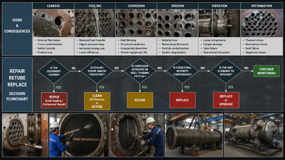
Repair vs. Retube vs. Full Replacement: How to Make the Engineering-Economic Decision
The wrong call here costs you either unnecessary capital or a repeat failure six months later. Neither is acceptable. Structuring the decision as three distinct intervention tiers—each with hard technical gates—removes the guesswork and gives you a defensible position with plant management and procurement.
Tier 1: Chemical Cleaning and Online Mitigation
Before any mechanical work, establish whether the degradation is fouling-driven or metal-loss-driven. Fouling is recoverable without shutdown in some configurations; metal loss is not. Chemical cleaning (CIP circuits, inhibited acid circulation, or online dispersant injection) addresses deposit-based efficiency loss but does nothing for corroded, cracked, or mechanically deformed tubes. If a UT scan shows wall thickness still within ASME or EN 13445 tolerances and your pressure differential has crept up 15–40% above clean baseline, a controlled chemical clean is the correct first move. Expecting cleaning to fix a tube that has lost 30% of its wall thickness is a maintenance error that will produce a leak event, not a recovery.
Tier 2: Mechanical Repair—Plugging, Re-Rolling, and Retubing
Tube plugging is the fastest field intervention, but it is governed by hard limits. TEMA standards and API 660 both converge on a practical ceiling of 10–15% of total tube count before the reduction in heat transfer surface area forces a process penalty that the plant cannot absorb. Beyond that threshold, the bundle is operationally compromised regardless of mechanical integrity. Even below that ceiling, plugging is only appropriate when the failure mode is localized—inlet-end erosion-corrosion in a defined zone, for example—not when you have distributed pitting across the bundle, which signals a fluid chemistry or materials selection problem that plugging will not address.
Re-rolling loose tube-to-tubesheet joints and re-gasketing shell flanges address mechanical seal failures without touching the bundle itself. These are low-cost interventions when the rest of the equipment is sound.
Retubing becomes the cost-justified path when the shell, baffles, and tubesheets pass UT inspection with remaining thickness within code-required minimums—typically verified against original design documentation plus applicable corrosion allowance. The cost components: tube material (carbon steel bundles sit in a meaningfully different range from duplex stainless or titanium), extraction and cleaning labor, hydrotest, and any surface treatment or coating. As a working rule of thumb, retubing runs 30–60% of the cost of a new equivalent exchanger when the pressure-retaining shell structure is sound. That ratio shifts unfavorably as shell diameter increases, because large-bore shells require significant rigging and alignment labor even on a retube scope.
Remaining Useful Life Assessment Before Committing Capital
Corrosion rate data from successive UT thickness surveys—ideally taken 12–24 months apart at the same mapped grid points—lets you calculate mils-per-year loss and project time to minimum allowable wall thickness. That projection becomes your replacement decision timeline. If projected RUL is under 18–24 months and a retube or repair would consume 8–12 weeks of your procurement and execution window anyway, the economics of going straight to replacement sharpen considerably.
A single UT inspection is sufficient to make a remaining useful life determination for a heat exchanger shell.False
RUL projection requires a minimum of two inspections separated by a known time interval to establish actual corrosion rate. A single-point measurement tells you current thickness but cannot tell you how fast you are losing it, which is the critical variable for scheduling replacement.
Full Replacement Triggers and TCO Framing
Replace, do not repair, when: shell corrosion allowance is consumed; the process service has changed to higher pressure or temperature ratings that require a new ASME VIII Div. 1 or PED 2014/68/EU mechanical design; or the existing geometry cannot deliver required duty with the degraded bundle and plugged tubes already in place.
The TCO model that actually moves a capex request through approval integrates three cost streams over a 5–10 year horizon: capital outlay (repair or replace), cumulative energy penalty from reduced thermal efficiency (fouling and reduced surface area both carry ongoing fuel or utility costs), and lost production cost from the statistical probability of an unplanned mid-campaign failure based on your RUL projection. A degraded exchanger running at 20% reduced thermal efficiency in a refinery preheat train can generate energy cost overruns that, compounded over three years, rival a significant fraction of replacement cost—before you account for a single unplanned outage. Build that calculation explicitly. It is the argument that converts a reliability recommendation into an approved purchase order.
Inspection Methods and Testing Protocols Used to Assess Heat Exchanger Condition
Choosing the wrong inspection technique for a given tube material wastes crew time and generates misleading fitness-for-service data. The choice is not arbitrary — it is driven by tube metallurgy, access constraints, whether the unit is online or offline, and the specific failure mode you suspect based on process history.
Eddy Current Testing for Non-Ferrous Tubes
ECT is the standard technique for admiralty brass, copper-nickel alloys, and titanium tubes. A probe driven through each tube induces alternating electromagnetic fields; discontinuities in conductivity and permeability produce a phase-shifted signal that trained analysts interpret as percent wall loss, pitting depth, or transverse cracking. Reporting follows a percent-wall-loss convention — a call of 40% wall loss on a standard tube-condition report means 40% of nominal wall thickness has degraded at that axial position. Most reliability programs set a repair or plug threshold at 60–80% wall loss, though the exact limit depends on design pressure and corrosion allowance built into the original specification.
The hard limitation: ECT does not work reliably on ferritic carbon steel tubes. Ferromagnetic material masks the eddy current signal, producing noise that overwhelms defect indication. Applying ECT to carbon steel tube bundles is a common field mistake that yields false-confidence results.
Remote Field Testing and Magnetic Flux Leakage for Carbon and Low-Alloy Steel Tubes
RFT was developed specifically to address ECT’s ferromagnetic limitation. The remote field probe transmits flux through the tube wall, picks up the attenuated signal two to three tube diameters downstream, and detects wall loss from both ID and OD surfaces with comparable sensitivity — typically detecting defects of 10–15% wall loss in practical plant conditions, though sensitivity degrades in heavily pitted tubes with irregular OD profiles. Scanning speed is slower than ECT, roughly 6–12 inches per second versus 20–30 for ECT, which affects inspection cost for large bundles.
MFL drives a strong magnetic field axially through each tube. Flux leakage at a defect is detected by hall-effect sensors. It handles heavy scale deposits better than RFT and offers faster throughput, but minimum detectable defect size in corroded carbon steel is generally coarser — around 15–20% wall loss — making it more suitable for screening than for precise fitness-for-service evaluation.
Ultrasonic Methods for Shell, Weld, and Tubesheet Inspection
Straight-beam UT with a grid scan remains the workhorse for shell-side corrosion mapping. Meaningful corrosion maps require grid densities of at least 25 mm × 25 mm in suspected active zones; coarser grids miss localized pitting that can perforate a shell before the next planned outage. Time-of-flight diffraction (TOFD) and phased array UT are appropriate for longitudinal and circumferential weld inspection on pressure-retaining shells, and for tubesheet thickness verification where roll-expansion or explosive bonding integrity is in question. Phased array is worth the day-rate premium when access limits conventional probe manipulation.
Eddy current testing produces unreliable defect indications on ferritic carbon steel tubes and should not be used as the primary inspection method for carbon steel tube bundles.True
ECT relies on electromagnetic induction in conductive, non-ferromagnetic materials. Carbon steel's ferromagnetic permeability overwhelms the eddy current signal, causing signal noise that masks genuine defect indications. ASME and industry NDT guidelines specify RFT or MFL for ferromagnetic tubes.
Hydrostatic and Pneumatic Pressure Testing
Per ASME Section VIII Div. 1 and ASME B31.3, hydrostatic test pressure is typically 1.3× MAWP (multiplied by the ratio of allowable stress at test temperature to allowable stress at design temperature). Hold time is generally 30 minutes minimum before inspection, though some owner specifications require 60 minutes for high-alloy or high-pressure units. Pneumatic testing — permitted when liquid cannot be tolerated in the system — uses 1.1× MAWP and demands a preliminary bubble-leak check at 25 psi before full pressurization. Stored energy in a pneumatically pressurized exchanger is orders of magnitude higher than a water-filled vessel of the same volume. Personnel exclusion zones, pressure relief path verification, and incremental step pressurization are not optional procedural niceties — they are mandatory precautions against catastrophic brittle or fatigue fracture.
Visual and Borescope Inspection After Bundle Extraction
Once a bundle is pulled, borescope inspection of tube bore surfaces catches deposit morphology, pitting geometry, and erosion-corrosion patterns that ECT percent-wall-loss numbers alone cannot characterize. Tubesheet face inspection verifies roll-joint tightness, ligament cracking between tube holes, and galvanic attack at bimetallic joints. Baffle alignment and anti-vibration strip condition are worth documenting photographically — displaced baffles cause flow-induced vibration that accelerates tube wear at mid-span, a root cause that reappears in the next campaign if not corrected during re-bundle.
Online Monitoring: Acoustic Emission, Soft Sensors, and Distributed Temperature Sensing
Acoustic emission monitoring detects the stress wave burst produced by active crack propagation — it distinguishes a growing defect from a dormant one, which periodic UT cannot do. Soft sensor fouling models use inlet and outlet temperature and flow measurements already present in the DCS to calculate a real-time fouling resistance factor, giving operations a running trend rather than a surprise at turnaround. Fiber-optic distributed temperature sensing mounted on shell exteriors can reveal hot spots or cold zones indicating internal maldistribution or localized fouling — useful on large surface condensers where conventional thermocouples give only zone-averaged readings. These online tools reduce the interval between detectable degradation and corrective action, which is where most of the economic damage actually accumulates.
Specifying a Replacement Heat Exchanger: Key Parameters That Prevent Repeat Failure
The single most expensive mistake in heat exchanger procurement is ordering a replacement unit to the original design specification. That specification reflects process conditions that existed at commissioning — often five, ten, or twenty years ago. Actual operating data routinely diverges from nameplate conditions, and if the new unit is sized and specified against outdated numbers, you are engineering the same failure mode into the replacement before it ships.
Thermal and Hydraulic Re-Rating Against Real Operating Data
Pull your DCS historian data for the 12–24 months before failure, not the original process datasheet. Actual fouling resistance values in refinery crude preheat service typically run 20–60% higher than TEMA-tabulated defaults, depending on crude blend, operating temperature, and flow velocity. Real inlet temperatures drift as upstream units are debottlenecked or feedstocks change. Actual flow rates in a mature plant often differ from design by ±15–25%. Feed all of this — measured fouling factors, real bulk temperatures, confirmed flow rates — into the thermal re-rating before you issue the RFQ. An undersized replacement will foul to the same heat duty deficit within one operating cycle.
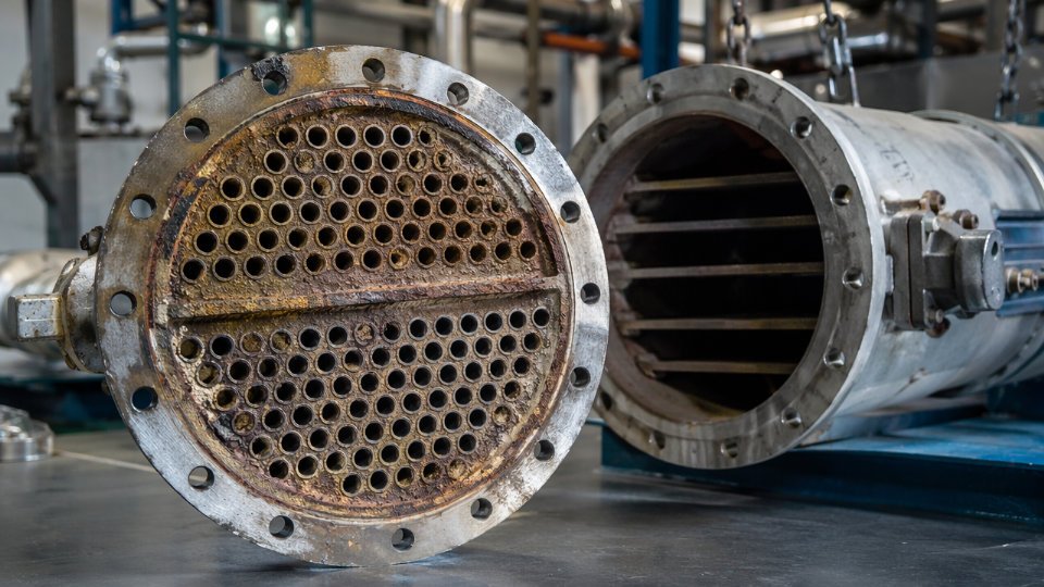
Material of Construction Upgrade Decisions
When the failed unit shows a corrosion rate history above roughly 0.1–0.2 mm per year on carbon steel, the question is no longer whether to upgrade — it is which alloy and at what cost-per-year-of-service. A simple framework: divide total installed cost by expected service life in years and compare across material options. A duplex 2205 bundle may cost 2.5–3× a carbon steel equivalent but deliver 3–4× the service life in chloride-bearing process water or sour gas condensate. Titanium Gr.2 makes sense in seawater-cooled services or where hydrochloric acid is present; Hastelloy C-276 is reserved for severely oxidizing or mixed-acid environments where nothing else holds up. Pull the actual fluid chemistry analysis — pH, chloride concentration, H₂S partial pressure, and oxygen content — not generic fluid classifications. Those four numbers drive the alloy decision more than anything else.
Specifying the replacement heat exchanger to original design data rather than actual operating conditions is a primary cause of repeat failure within one to two operating cycles.True
Fouling factors, flow rates, and inlet temperatures in mature plants routinely diverge from original design values; a unit sized against stale data will be thermally undersized or under-specified for real corrosion conditions from the first day of service.
Tube Gauge, Pitch, and Bundle Configuration
Moving from 14 BWG to 12 BWG tube wall adds mechanical life in erosion-prone or high-velocity services and improves resistance to vibration-induced wear at baffle supports — at the cost of a modest reduction in heat transfer area for the same shell diameter. In heavy fouling services, changing from triangular to square pitch (or rotating a triangular layout 90°) increases shell-side cleanability significantly; square pitch allows mechanical rodding access, which triangular layouts do not. Specify which cleaning method your maintenance team will actually use, and design the pitch to match it.
For bundle type selection: floating-head designs give full mechanical access for inspection and tube replacement in fouling or corrosive services despite higher initial cost. U-tube bundles eliminate one tubesheet and reduce shell length but make individual tube replacement impractical. Fixed-tubesheet units are only appropriate where shell-side fouling is low and differential thermal expansion is manageable. Specify the full bundle pull-out clearance as a hard layout constraint — a bundle that cannot be pulled due to a structural steel interference discovered during installation is a costly field problem.
Nozzle Orientation, Supports, and Expansion Provisions
Nozzle orientation must be confirmed against the as-built piping isometrics, not the original GA drawing, which may not reflect field modifications. Saddle design and base plate dimensions need to match existing civil foundations precisely; a 50 mm shift in nozzle elevation can require pipe spool re-fabrication. For high-temperature services above roughly 200–250°C, confirm whether the existing piping expansion loop has enough flexibility for the replacement unit’s thermal growth — a unit with slightly different face-to-face length will shift the anchor points.
Code and Certification Requirements for International Projects
For export or EPC projects, define the governing code before issuing the RFQ — not after. ASME VIII Div.1 with U-stamp is required for most North American and Middle Eastern projects and adds 4–8 weeks to lead time through Authorized Inspection. PED 2014/68/EU with CE marking is mandatory for European installations and requires a Notified Body. GB 150 applies to China-sited equipment and requires CNEX or TSG certification from a licensed Chinese pressure vessel manufacturer. Third-party inspection by Lloyd’s, Bureau Veritas, or TÜV adds documentation requirements — material traceability reports, WPS/PQR records, hydrostatic test witness, and data books — that must be scoped into the vendor’s price and schedule from day one. Specifying TPI after order placement is a reliable way to extend lead time by 3–6 weeks and generate commercial disputes.
Preventive Maintenance and Anti-Fouling Strategies That Extend Heat Exchanger Service Life
Fouling and corrosion don’t announce themselves—they accumulate quietly, compound interest-style, until the efficiency penalty becomes a production constraint or the tube wall finally gives way. A structured prevention program addresses this before the instrument readings force your hand.
Cooling Water Treatment: Chemistry That Keeps Scale and MIC in Check
Recirculating cooling water systems are the most common fouling vector in shell-and-tube exchangers used for process cooling. A competent water treatment program runs on three parallel tracks: scale inhibition, corrosion control, and biological control.
For scaling, phosphate-based inhibitors remain workhorses in moderate-hardness systems, but where calcium and silica loads are high, molybdate or polymer-based programs often outperform on deposit control. Azole-based inhibitors (benzotriazole, tolyltriazole) target copper alloy tube protection specifically—if your bundles are admiralty brass or 90/10 Cu-Ni, azole dosing is non-negotiable. Corrosion inhibitor selection depends on metallurgy, pH operating band (typically 7.0–8.5 for mixed-metal systems), and whether you’re in once-through or recirculating service.
Biocide scheduling matters more than most operators appreciate. Microbiologically influenced corrosion can pit carbon steel tubes within months under the right biofilm conditions; the failure mode looks identical to pitting corrosion from other causes until you culture the deposits. Oxidizing biocides (chlorine, bromine-based) dosed on a 2–3 times per week shock schedule typically keep planktonic counts suppressed, but biofilm eradication requires periodic non-oxidizing biocide alternation. Blowdown frequency directly controls cycles of concentration—running excessively high cycles to save water almost always costs more in fouling and under-deposit corrosion than the water savings justify.
Online Chemical Cleaning: Dispersants and Antifoulants in Continuous Service
Crude preheat train exchangers—where heavy hydrocarbon fouling is the norm—respond well to continuous or slug-dosed antifoulant injection upstream of the exchanger bundle. Realistic fouling factor improvement from a well-tuned dispersant program ranges from 15–35% reduction in fouling resistance accumulation rate, depending on crude blend and operating temperature. The program needs monitoring: track the calculated overall heat transfer coefficient (U-value) weekly during early operation to establish your baseline fouling trajectory before and after chemical intervention. If U-value decline flattens, the chemistry is working. If the rate doesn’t change, reformulate before you’ve wasted months.
Velocity Management and Hydraulic Design Trade-Offs
Maintaining tube-side velocity above 1.0–1.5 m/s in water service is a practical threshold for suppressing particulate deposition and limiting biological fouling attachment. Below roughly 0.8 m/s, settling becomes significant in systems with suspended solids, and biofilm accumulation accelerates on stagnant surfaces. Increasing pass count raises velocity without upsizing the exchanger shell, but it comes at a pressure drop penalty—each additional pass roughly doubles the tube-side ΔP for the same flow rate. That trade-off has to be evaluated against pump capacity and system hydraulics at the design stage, not during a retrofit.
Tube-side velocity below 0.8 m/s in cooling water service significantly accelerates both particulate fouling and biofilm formation in shell-and-tube heat exchangers.True
This is consistent with TEMA guidelines and widely published fouling research; minimum velocity recommendations of 1.0–1.5 m/s for water service are standard practice in thermal design to maintain turbulent flow and reduce deposition tendency.
Mechanical Cleaning During Planned Shutdowns
Pigging and high-pressure hydrojetting (operating pressures typically 700–1,500 bar depending on deposit hardness) are the standard offline cleaning methods for straight-tube bundles. Cleaning frequency should be driven by fouling rate trend data, not a fixed calendar—a refinery crude preheat exchanger in heavy sour service may need cleaning every 12–18 months, while a clean condensate cooler might go 5–7 years between mechanical cleanings. Service severity classification—light, moderate, severe—based on process fluid characterization and observed fouling rates is a better scheduling framework than arbitrary annual mandates.
U-tube and fixed-tubesheet configurations cannot be mechanically cleaned on the tube-side with a pig; that constraint should factor into exchanger selection when the service carries moderate or higher fouling potential.
Controlled Startup, Bypass Management, and Commission Flushing
Thermal shock during startup is an underappreciated damage mechanism. Ramping a cold exchanger into full-flow hot service too quickly imposes differential thermal expansion that can work-harden tube-to-tubesheet joints and initiate crevice conditions over time. Startup ramp rates of 15–25°C per hour on the process side are a common operational guideline for carbon steel equipment; titanium and high-alloy units are less sensitive, but the practice costs nothing and eliminates risk.
During low-load or turndown periods, bypassing flow rather than running a dead-leg through an exchanger is the right call. Stagnant process or cooling water in a tube bundle creates concentrated scaling and accelerates MIC at exactly the spots that are hardest to inspect later.
Commission-phase flushing before initial startup removes weld spatter, mill scale, and construction debris that would otherwise lodge in tube inlets and initiate erosion-corrosion. This step is frequently skipped under schedule pressure and routinely results in localized tube failures within the first operating year.
Condition-Based Maintenance: KPI Thresholds That Drive Intervention Timing
A CBM program built on three KPIs gives maintenance teams defensible intervention triggers. Track calculated U-value (derived from operating temperatures and flow measurements): a 15–20% decline from clean baseline typically justifies a chemical cleaning decision. Monitor tube-side and shell-side pressure drop independently—rising ΔP at constant flow indicates fouling accumulation or debris blockage. For exchangers in vibration-susceptible service (high shell-side velocities, two-phase flow, or long unsupported tube spans), periodic vibration monitoring on the shell provides early warning of acoustic resonance or flow-induced fatigue before tube damage is visible.
Set alert thresholds conservatively enough to allow a planned intervention window before the degradation hits process constraints. Waiting until process throughput is visibly impacted means you’ve already conceded weeks of efficiency loss and may be facing an emergency maintenance event rather than a scheduled turnaround task.
Frequently Asked Questions About Heat Exchanger Failure
How do I know if my heat exchanger has a tube leak?
The most reliable early indicator is a measurable pressure differential shift between the shell side and tube side that cannot be explained by flow changes. If your higher-pressure stream is contaminating the lower-pressure stream, you will often see this first in process analyzer data or downstream product quality tests before any visible symptom appears. During operation, watch for unexplained changes in conductivity, pH, or tracer concentration in utility streams. On a cooling water system, hydrocarbon odor or a sheen in the return water header is a classic field signal.
During shutdown, a pneumatic pressure test with the bundle pulled and one end blanked off identifies leaking tubes within minutes. Helium leak testing is the preferred method for high-consequence services — helium is pumped into the tube side while a mass spectrometer probe scans the shell side, and it will locate a leak that passes a hydrostatic test. Bubble testing (flooding tubes with air and submerging in water) is lower cost and adequate for low-pressure services. Eddy current testing, discussed in the inspection section, can locate wall-thinning before a tube actually fails.
Can a heat exchanger be repaired in place without pulling the bundle?
Yes, within limits. Tube plugging is the most common in-situ fix: a tapered plug is driven or welded into each end of a leaking or thinned tube, taking it out of service. Most TEMA standards permit plugging up to roughly 10–15% of total tube count before you are required to retube or replace, though the actual threshold depends on the thermal margin designed into the original unit — consult your heat duty calculations before deciding. Chemical cleaning can be done under bypass conditions without pulling the bundle, which addresses soft fouling deposits. What you cannot fix in place is significant tube-sheet face corrosion, severe baffle erosion, or shell-side nozzle cracking. Those require a bundle pull or full shell replacement.
How long does a heat exchanger last?
Realistic service life runs 10–30 years, and that range is almost entirely driven by three variables: service severity (corrosive or erosive media compresses life sharply), material selection (carbon steel in an H₂S-wet service may last 8–12 years; titanium or duplex stainless in the same service can double that), and maintenance quality (units that are chemically cleaned on schedule and inspected every 2–4 years routinely outlive those that are run-to-failure). Units in clean utility service with good water treatment programs are the ones that approach 30 years. Crude oil preheat trains in refinery service rarely see beyond 15 years on tube bundles without at least one retube.
What is the difference between fouling and scaling?
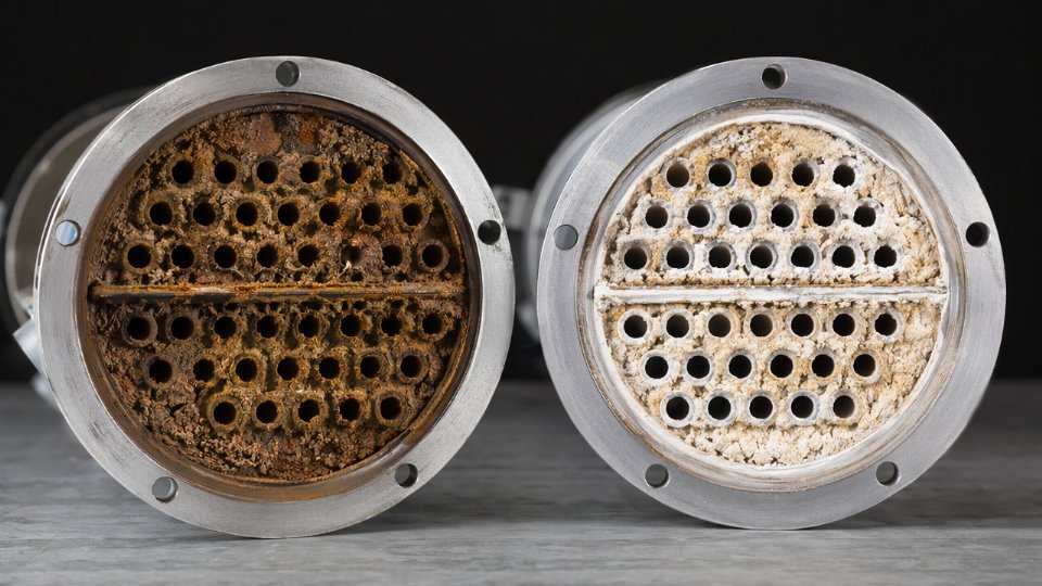
Fouling is the general accumulation of any unwanted deposit on heat transfer surfaces — biological growth, corrosion products, particulate matter, or process fluid polymerization all qualify. Scaling is a specific subset: crystalline mineral deposits (calcium carbonate, calcium sulfate, silica) that precipitate out of water or process streams as temperature and concentration change. The operational distinction matters because they need different remediation. Scaling responds well to acid cleaning (typically dilute HCl or inhibited sulfamic acid, depending on deposit composition). Biological or organic fouling requires biocides and alkaline or solvent-based cleaning. You can often distinguish them by deposit sampling and X-ray fluorescence (XRF) analysis — scaling deposits are primarily inorganic minerals, while fouling deposits show high organic or iron content.
When should I repair vs. replace a heat exchanger?
If the repair cost exceeds 50–60% of replacement cost and the unit is already past two-thirds of its design life, replacement is almost always the better economic decision once you factor in recommissioning risk and the near-certainty of repeat failure within a short interval. Plugging a few tubes in a unit with remaining wall thickness above minimum is a straightforward in-campaign repair. A unit with widespread under-deposit corrosion, compromised tube sheets, or a shell that no longer meets current code is a replacement candidate regardless of short-term repair cost. Sparing strategy matters too — if you have no installed spare, a single-unit failure triggers a full process shutdown, which changes the economic calculus entirely.
Does heat exchanger failure affect product quality or safety?
Cross-contamination is the most direct product quality risk. In a steam-heated process fluid exchanger, a tube leak allows process fluid into the condensate return system, with consequences ranging from steam system fouling to hazardous material release depending on the service. In a feedstock-versus-product exchanger, cross-contamination can render an entire product batch off-spec. From an HSE standpoint, leakage of high-pressure hydrocarbons or toxic process fluids into low-pressure utility streams creates a potential ignition or exposure hazard that must be reported under most plant process safety management (PSM) systems. Document the failure mode, isolation response, and root cause immediately — many regulatory frameworks (OSHA PSM, EU Seveso III, local equivalents) require incident investigation records for pressure equipment failures involving hazardous fluids.
A tube leak in a high-pressure hydrocarbon service exchanger that routes into a cooling water system can create a flammable atmosphere in the cooling tower — a recognized PSM incident precursor.True
This failure pathway is documented in refinery incident investigation literature and is a recognized scenario in API 510 and OSHA PSM guidelines covering heat exchanger integrity management.
How much does it cost to replace a heat exchanger in a chemical plant?
Tube bundle replacement alone typically runs $15,000–$250,000, depending on shell diameter, tube count, and material grade — a carbon steel bundle in a standard shell is at the low end; a titanium or duplex stainless bundle in a large-diameter shell sits at the high end or above. A full shell-and-tube exchanger replacement in high-pressure service, including new vessel, installation, piping tie-ins, and recommissioning, can exceed $500,000. What drives cost variation most: material specification (alloy surcharges can multiply fabrication cost by 3–5×), ASME or PED certification requirements (which affect both fabrication time and inspection costs), site access constraints, and whether the replacement must be engineered-to-order against a non-standard shell dimension. Lead times range from 6 to 20 weeks for certified replacement units — longer for exotic alloys or large shells — which is why lifecycle cost analysis consistently favors maintaining a critical spare for high-consequence exchangers.