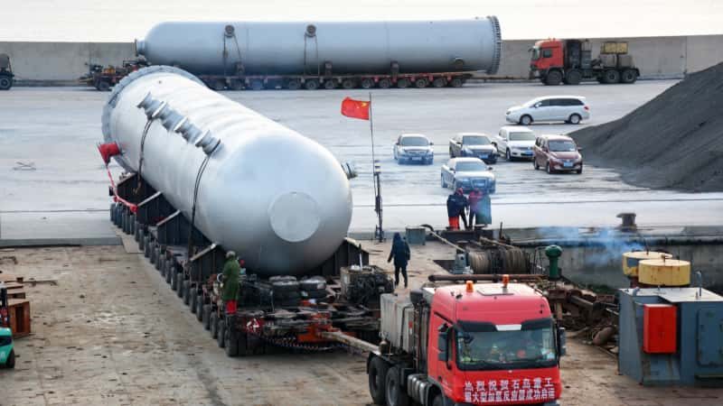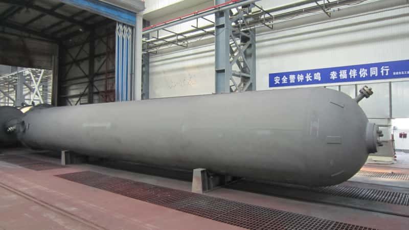

A pressure vessel clears final inspection, documentation looks complete, and the delivery date is locked — then the site team flags that the test method doesn’t match the service conditions, or the pneumatic test record lacks the required risk assessment. At that point you’re not looking at a paperwork correction; you’re looking at re-inspection holds, potential witness re-scheduling across time zones, and vessel quarantine that can push commissioning back by weeks. For an EPC project running on a tight critical path, that delay compounds fast: idle installation crews, late mechanical completion, and liquidated damages clauses that don’t care whose fault the gap was.
Hydrostatic testing fills the vessel with liquid — usually water — and pressurizes it to 1.25–1.5× design pressure depending on the applicable code (ASME VIII, EN 13445, or GB 150), making it the default and lower-risk method. Pneumatic testing uses compressed gas at 1.1–1.25× design pressure and is only permitted under specific conditions because a gas-filled vessel stores roughly 200 times more energy than a liquid-filled one at the same pressure, making a rupture far more destructive. Choosing the wrong method, or failing to document the right one correctly, creates acceptance, safety, and schedule risks that follow the vessel from the shop floor to the operating plant.
What most procurement specifications get right is naming the test pressure. What they consistently miss is the conditional logic behind which test is actually permissible for a given vessel — and what documentation the receiving authority will demand before that vessel is cleared for service. The distinction between hydrostatic and pneumatic testing runs deeper than a pressure multiplier. It reaches into weld joint efficiency assumptions, stress relief requirements, witness hold points, and the liability chain between manufacturer, inspector, and EPC owner. Understanding that chain before you place the purchase order is the difference between a clean delivery and an expensive argument at the factory gate.
How Hydrostatic and Pneumatic Tests Actually Work: Mechanics, Pressures, and Code References
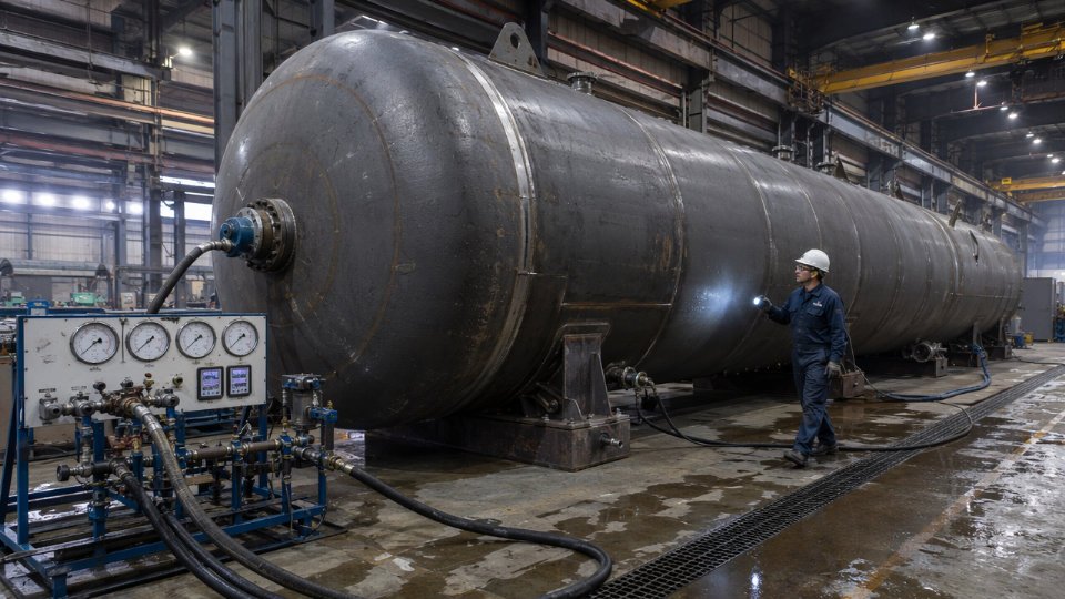
Understanding the mechanics of each method is the foundation for evaluating any vendor’s test proposal. A document that simply reads “pressure test completed per ASME” tells you almost nothing useful. Knowing what that actually requires — step by step, pressure by pressure — puts you in a position to ask the right questions before the vessel ships.
Hydrostatic Test Procedure
The hydrostatic test under ASME Section VIII Div.1 UG-99 begins with filling the vessel completely with water, or another suitable liquid, while simultaneously venting all trapped air. That venting step matters more than most procurement checklists acknowledge. A trapped air pocket transforms part of a hydrostatic test into an inadvertent pneumatic test, concentrating stored energy at the high point of the vessel. Any competent test procedure specifies vent locations explicitly, and the inspector should verify that fluid runs clear and continuous from every vent before pressurization starts.
Pressurization is then applied gradually — typical shop practice is to hold at approximately 50% of test pressure, visually confirm no anomalies, then continue. ASME does not prescribe a rigid ramp rate in UG-99 itself, but most Authorized Inspection Agency (AIA) procedures and manufacturer quality plans specify something in the range of 0.1 to 0.3 MPa per minute, depending on vessel volume and wall thickness. Once test pressure is reached, the hold period under UG-99 is a minimum of 30 minutes, though large-volume vessels or those with thick walls often run 60 minutes or longer at the inspector’s discretion.
During the hold, the inspection walkdown covers every weld seam, nozzle connection, flange face, and reinforcement pad — looking for weeping, seepage, or visible deformation. Pressure gauge readings are logged at intervals. After inspection is complete, pressure is released slowly; rapid depressurization can induce flash vaporization in the test fluid and impose dynamic loads the vessel was not designed to handle.
EN 13445-5 follows similar logic but sets the test pressure multiplier at 1.25× design pressure, corrected for material strength at test temperature versus design temperature. GB 150 also specifies 1.25× for liquid pressure tests. The 2023 edition of ASME Section VIII Div.1 revised the hydrostatic multiplier to 1.3× (previously 1.5× in older editions, then adjusted), calculated against the allowable stress ratio at test temperature — so the actual test pressure you compute will depend on your material, its listed allowable stress values, and which edition of the code governs your purchase order.
Pneumatic Test Procedure
ASME UG-100 permits pneumatic testing only under specific, documented conditions — not as a routine alternative. The procedure is meaningfully more involved than hydrostatic testing, not less.
It begins with a mandatory preliminary leak test at no more than 170 kPa (25 psi) gauge, using a soap solution or equivalent bubble detection on all joints and connections. Only after that low-pressure check passes does pressurization continue. From there, pressure is increased in increments — typically 10% of test pressure per step — with a hold period at each increment before proceeding. The final test pressure under ASME UG-100 is 1.1× design pressure. EN 13445-5 also specifies 1.1×. GB 150 is slightly higher at 1.15×.
Lower pneumatic test pressure multipliers mean pneumatic testing is safer than hydrostatic testingFalse
The lower multiplier exists precisely because compressed gas stores roughly 200 times more energy than an equivalent volume of liquid at the same pressure. A pneumatic test at 1.1× is already a far higher-consequence event than a hydrostatic test at 1.3×. The multiplier compensates for risk; it does not eliminate it.
Acoustic emission monitoring is often specified as an additional safeguard during pneumatic testing on larger or higher-risk vessels, allowing inspectors to detect crack propagation before it reaches critical size. Safety exclusion zones — typically established by the responsible engineer based on vessel volume, pressure, and stored energy calculations — must be defined in writing before the test begins. Personnel not directly involved in the test have no business being within that perimeter.
Side-by-Side Pressure Multiplier Reference
| Code | Hydrostatic Multiplier | Pneumatic Multiplier | Key Dependency |
|---|---|---|---|
| ASME VIII Div.1 (2023) | 1.3× | 1.1× | Allowable stress ratio at test temperature |
| EN 13445-5 | 1.25× | 1.1× | Material strength correction factor |
| GB 150 | 1.25× | 1.15× | Design pressure and material grade |
The gap between hydrostatic and pneumatic multipliers is not a design concession — it is a direct acknowledgment of stored energy risk. For procurement teams reviewing vendor test packages, the multiplier is just the starting point. The test fluid, hold duration, inspection scope, AIA sign-off requirements, and exclusion zone documentation are what separate a defensible acceptance record from a paperwork exercise.
Stored Energy, Failure Modes, and Why Pneumatic Testing Demands a Formal Risk Assessment
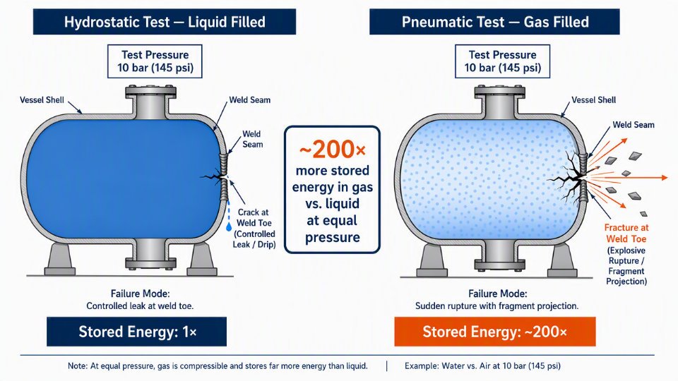
The single most important number in this comparison is roughly 200. At the same internal pressure and vessel volume, compressed gas stores approximately 200 times more elastic strain energy than a liquid-filled vessel. That ratio is not a regulatory convention or a conservative estimate — it comes directly from the compressibility difference between gases and liquids. Water is nearly incompressible; when a hydrostatic test vessel fails, the stored energy releases almost instantaneously as a leak or a localized crack, with very little driving force to propagate that crack catastrophically. Compressed gas, by contrast, behaves like a mechanical spring wound to failure pressure. The moment a flaw reaches critical size, the full stored energy drives fracture propagation faster than any protective response can intervene.
The Physics of Brittle Fracture Under Pneumatic Loading
Fracture mechanics explains why this matters at the test stage specifically. Most weld defects that survive fabrication inspection — small slag inclusions, lack-of-fusion regions, tight hydrogen-induced cracks — are subcritical at operating loads. Pneumatic test pressure runs 1.1–1.25× design pressure depending on code (versus 1.25–1.5× for hydrostatic), yet the energy available to drive a running crack is orders of magnitude higher. Once a defect reaches its critical crack-tip stress intensity factor under pneumatic loading, the gas expansion accelerates crack propagation across the shell. The result is not a controlled leak you can observe and depressurize. It is brittle fracture with shrapnel projection, potentially at velocities sufficient to penetrate adjacent equipment, structural steelwork, or personnel. Test temperature amplifies this: vessels tested below the nil-ductility transition temperature of the base metal are at elevated brittle fracture risk regardless of test method, but the consequence severity under pneumatic conditions is disproportionately worse.
Failure Modes Unique to Pneumatic Testing
In a hydrostatic test, the dominant failure signal is a visible leak — a wet spot at a weld toe, a weeping flange face, a drop on the pressure gauge. The vessel loses pressure slowly, the crew evacuates the area, and the defect is identified and repaired. The consequence is schedule delay and repair cost, rarely injury.
Pneumatic failures present differently. Weld defects that would seep under hydrostatic pressure can propagate to full-thickness fracture before the pressure gauge moves meaningfully. Stress corrosion at the test temperature — relevant when residual surface contamination or incompatible test gas moisture is present — can initiate cracking at stresses well below yield. Fitting and flange blowouts are a particular hazard because small-bore connections are often the weakest assembled joint; under pneumatic pressure, a loose or misthreaded connection can eject as a projectile rather than simply dripping. None of these failure modes give the crew adequate warning time.
Pneumatic testing is a standard alternative that any vessel can use when hydrostatic testing is inconvenient.False
Under ASME Section VIII Div.1 UG-100, pneumatic testing is only permitted when the vessel cannot be safely filled with liquid or when the owner provides written authorization backed by a documented risk assessment. It is a permitted exception, not a routine equivalent.
What a Formal Pneumatic Test Risk Assessment Must Cover
ASME UG-100 and European PED Article 3 / Annex I both require documented justification before pneumatic testing proceeds. In practice, a compliant risk assessment for a pneumatic test should address at least five areas.
Hazard identification must catalog every potential failure point: all weld seams and their PWHT and NDE status, all pressure-boundary penetrations, all assembled joints, and the vessel support structure. Any connection that was not radiographed or ultrasonically examined to the same standard as the main seams becomes a specific line item.
Exclusion zone calculation determines the minimum safe standoff distance based on vessel volume, test pressure, and fragment projection models. For a typical mid-size pressure vessel in the 5–20 m³ range, exclusion zones often extend 15–50 m depending on geometry and site conditions. This calculation must be documented, not estimated verbally on the day of the test.
The emergency response plan must be site-specific and pre-approved: evacuation routes, communication protocols, first-aid staging, and a written procedure for controlled depressurization if anomalies appear during pressurization hold. Remote pressure monitoring — rather than personnel standing near the vessel reading gauges — is strongly recommended and increasingly required by third-party inspection bodies.
Third-party inspector sign-off closes the loop. The Authorized Inspector or Notified Body must review and countersign the risk assessment before the test begins, not after. EPC procurement teams should verify this sign-off is a mandatory hold point in the inspection and test plan, not a notification point that can be cleared retroactively.
An operational warning worth stating plainly: if a vendor proposes pneumatic testing for schedule convenience — because the vessel is already insulated, or draining hydrostatic water is inconvenient for the test cell — that is not a code-compliant justification. Accepting it without written risk assessment documentation transfers liability to the EPC buyer at acceptance.
Code-Permitted Scenarios Where Pneumatic Testing Is the Only Viable Option
Not every vessel can be hydrostatically tested, and the codes recognize this. ASME VIII UG-100, EN 13445-5 clause 10.3, and GB 150.4 each carve out specific conditions where pneumatic testing is permitted — but in every case, the burden falls on the manufacturer and owner to document why the default hydrostatic route is genuinely impractical, not merely inconvenient. As a buyer, your job is to evaluate that justification rather than accept it at face value.
Internal Linings and Coatings That Water Destroys
Glass-lined reactors represent the clearest case. The glass lining is fused to the steel shell at temperatures above 800 °C; prolonged contact with water — particularly if the vessel will sit partially filled during hold periods — can cause micro-cracking or delamination, especially near nozzle welds where thermal mass differs from the shell. Rubber-lined separators face a different but equally real problem: water trapped beneath a disbonded section during pressurization can cause localized ballooning or adhesion failure that only becomes visible weeks after commissioning.
Catalyst beds and molecular sieve vessels add another dimension. The catalyst or adsorbent is frequently loaded before shipment to reduce on-site labor costs. Introducing water at test pressure would saturate the bed, require full replacement, and push delivery out by weeks. In these cases, pneumatic testing with a sensitive leak detection method — typically soap-bubble inspection or helium tracer depending on the required sensitivity — is the only option that preserves the internal condition the process engineer specified.
Pneumatic testing with supplemental leak detection is code-accepted as an equivalent alternative when internal coatings or pre-loaded internals make hydrostatic testing impractical, provided a written risk assessment is submitted.True
ASME VIII UG-100 explicitly permits pneumatic testing when the owner provides written authorization and the vessel design has been reviewed for suitability; it does not waive the requirement for a concurrent leak test at a lower hold pressure.
Structural Support and Weight Limitations
Large-diameter, thin-shell, low-pressure vessels — atmospheric or near-atmospheric storage tanks, for instance — can experience shell buckling or foundation overload if filled with water. A carbon steel tank designed for 0.05 MPa internal pressure and 3 m diameter will carry several tonnes of water during hydrotest; if the skid or structural frame was engineered only for operating loads plus wind, that water weight can exceed the design margin by a significant factor depending on aspect ratio and support spacing.
Skid-mounted heat exchangers destined for offshore platforms face a similar constraint. Offshore topsides structures have strict weight envelopes, and a shell-and-tube exchanger with a large shell-side volume can add 2–6 tonnes of water weight that the temporary test stand at the fabrication shop simply cannot handle safely. The responsible solution is pneumatic testing with the vessel fully supported per its final installation configuration, or a pneumatic leak test combined with a prior hydrostatic shell test completed before internals are assembled.
Cryogenic and Moisture-Sensitive Process Services
Vessels designed for liquid nitrogen, liquid oxygen, or LNG service cannot tolerate residual moisture. Even aggressive hot-air drying after a hydrostatic test leaves moisture trapped in crevices around nozzle reinforcing pads, in threaded connections, and under weld backing rings. At cryogenic temperatures that residual moisture freezes, blocks instrumentation taps, and — in oxygen service — creates a contamination and ignition risk serious enough to fail the commissioning inspection.
For these services, pneumatic testing with dry nitrogen or dry instrument air at a controlled pressurization rate (typically no faster than 0.35–0.70 MPa per minute, with hold periods at 50% and 100% of test pressure) is not a shortcut. It is the engineering-correct choice. The risk assessment burden does not disappear, but it shifts toward controlling the pressurization environment rather than justifying departure from the liquid fill method.
What Buyers Must Require in the Vendor Documentation Package
Accepting a pneumatic test without proper paperwork is a procurement mistake that surfaces during third-party inspection, insurance underwriting, or incident investigation. At minimum, require the following before the test is witnessed or signed off:
- A signed engineering justification memo identifying the specific code paragraph invoked (e.g., ASME VIII UG-100(b), EN 13445-5 §10.3.2) and the precise technical reason hydrostatic testing is not viable for this vessel
- The risk assessment document or reference number, confirming that stored energy calculations have been reviewed and exclusion zone distances established
- The alternative leak test method selected, the detection sensitivity achieved, and the hold pressure and duration used
- Written owner or owner’s representative authorization, which ASME explicitly requires as a condition of using UG-100
A vendor who cannot produce these documents within a few working days of your request is telling you something about how the test was actually planned and executed. That is the signal worth acting on.
Impact on Weld Quality, NDE Scope, and Pre-Test Inspection Hold Points
The pressure test you specify doesn’t just happen at the end of fabrication — it reaches backward through the entire manufacturing sequence and reshapes every NDE and inspection decision made along the way. Buyers who treat the test method as an afterthought in the purchase order will find themselves negotiating scope changes mid-fabrication, when leverage is gone and schedule pressure is real.
How Test Method Connects to Joint Efficiency and Wall Thickness
Under ASME Section VIII Division 1, the joint efficiency factor (E) assigned to a weld category directly affects the allowable stress used in thickness calculations. A vessel built with full radiographic examination (100% RT) on Category A and B seams qualifies for E = 1.0, allowing the designer to use the full allowable stress value and — all else equal — produce a thinner shell. Spot radiography drops that to E = 0.85, and no radiography to E = 0.70. Those reductions translate directly into added wall thickness, added material cost, and added weight.
Here is where test selection matters upstream: a vessel designed for hydrostatic test at 1.25–1.5× design pressure and built to full RT qualifies for the highest joint efficiency and the thinnest allowable wall. If a buyer later switches to pneumatic test after the design is frozen, the NDE package must be upgraded — typically to 100% RT or UT across all pressure welds — to satisfy the more stringent pre-test requirements that codes and safety practice demand. Redesigning the wall thickness at that stage is rarely practical. The cost consequence is a forced NDE scope increase with no geometry benefit.
NDE Requirements for Pneumatic Testing Are Categorically Stricter
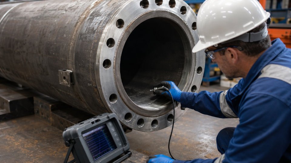
A hydrostatic test allows some residual weld flaws to be revealed gradually — leaks manifest as seepage, and the incompressible fluid limits the energy released if a defect propagates. Pneumatic testing eliminates that margin. Any pre-existing planar defect — a lack-of-fusion in a longitudinal seam, an un-detected undercut at a nozzle junction — can become a fast fracture initiation point under stored pneumatic energy that runs 200× higher than the equivalent hydrostatic condition.
That physics reality is why the expected pre-test NDE package for a pneumatically tested vessel typically includes: 100% radiographic or ultrasonic testing on all longitudinal and circumferential pressure welds; magnetic particle inspection (MPI) or liquid penetrant testing (PT) on all nozzle attachment welds and structural attachment welds; hardness survey and documented PWHT verification on any P-number material or dissimilar metal joint requiring post-weld heat treatment. PWHT verification is not a formality — an uninspected furnace cycle that ran short on temperature or soak time leaves a vessel with residual stress that a pneumatic test can exploit catastrophically.
Pneumatic testing requires a stricter NDE package than hydrostatic testing under most recognized pressure vessel codes.True
ASME Section VIII UG-100, EN 13445-5, and GB 150 all impose additional examination requirements when pneumatic testing is substituted for the default hydrostatic test, reflecting the substantially higher stored energy risk.
ITP Hold Points vs. Review Points — Get This Right Before Fabrication Starts
A well-structured Inspection and Test Plan assigns each checkpoint a clear status: Hold (work cannot proceed until the third-party inspector or owner representative physically witnesses and signs off), Witness (inspector is notified and should attend, but work may proceed after a defined waiting period), and Review (document review only, no physical attendance required).
For pressure vessels going to either test method, these are the checkpoints that should carry Hold status in any defensible ITP: dimensional inspection after shell rolling and head forming, weld map review against the approved fabrication drawing before welding begins, positive material identification (PMI) on base materials and filler metals for any alloy content requirement, PWHT chart review and hardness verification where specified, nozzle orientation and flange face finish inspection after final machining, and the pressure test itself — witnessed in real time with a calibrated, certified test gauge.
Review-point status is typically acceptable for mill certificate review, welding procedure qualification records, and welder continuity log verification, provided the quality management system has been audited. Flipping a Hold to a Review on the pressure test witness — something vendors occasionally propose to ease scheduling — is a risk transfer to the buyer. Reject it. A pressure test conducted without witness provides no independent verification that the specified hold pressure was reached, maintained for the required duration, or that the system was correctly isolated.
The practical consequence of a poorly structured ITP is straightforward: defects caught at a dimensional check or weld map review cost hours to correct; the same defects found during or after a pneumatic test can cost lives and certainly cost weeks of schedule, full vessel replacement, and regulatory incident reporting.
Documentation the EPC Buyer Must Receive Before and After Pressure Testing
Most schedule slippage at the vessel-release stage doesn’t come from failed tests. It comes from missing or incomplete paperwork discovered at the last hold point, when the third-party inspector refuses to sign off and the vessel is already sitting in the yard waiting for a truck. Building the documentation package into the purchase order — not the inspection and test plan as an afterthought — is the single most reliable way to prevent that scenario.
Pre-Test Documents That Must Be in Hand Before Pressurization Begins
The approved test procedure comes first. It should specify the test medium, the pressurization sequence and rate, hold duration, pressure gauge locations, vent locations, and the acceptance criteria. A procedure that simply states “hydrotest to 1.5× design pressure” is not sufficient. You need step-by-step instructions that a shop floor technician and a third-party inspector can follow independently and reach the same conclusion about whether the test passed.
Gauge calibration certificates are non-negotiable and frequently overlooked. Every pressure gauge used during the test — including any backup gauges — must have a current calibration certificate traceable to a national metrology standard (NIST in the United States, PTB in Germany, NIM in China, and so on). Certificates should show the calibration date, the calibration laboratory’s accreditation number, and the gauge’s uncertainty range. A gauge last calibrated fourteen months ago on a vessel with a twelve-month calibration interval is not a minor paperwork issue; it invalidates the test record.
For hydrostatic testing on austenitic stainless steel vessels, the water quality report is critical. Chloride-induced stress corrosion cracking can initiate during or after a hydrotest if water chloride content is too high. Most codes and material-specific guidelines set the limit somewhere between 25 ppm and 50 ppm depending on operating temperature, material grade, and post-test drying capability. Require a laboratory water analysis report, not a verbal assurance from the shop.
Third-party inspector hold-point notification records close out the pre-test package. The notification should be time-stamped and show the inspector’s acknowledgment. If your contract names a specific inspection body — Bureau Veritas, TÜV, SGS, or a client-nominated inspector — their written confirmation that they received the hold-point notice and attended (or formally waived attendance) is part of the legal record.
Test Records: What the Pressure Chart Must Actually Show
A time-stamped pressure chart or data logger printout is the core test record. Strip chart recorders are still common; digital data loggers are increasingly standard. Either format must show the full pressurization sequence, the hold period at test pressure, and the controlled bleed-down. A chart that shows only the peak pressure and a flat hold line tells you nothing about how the vessel behaved during pressurization or whether pressure bled off unexpectedly during the hold.
Ambient temperature and test medium temperature logs matter more than most buyers realize. ASME Section VIII Div.1 has specific minimum metal temperature requirements during hydrostatic testing to avoid brittle fracture. If the test was conducted at 4°C in an unheated workshop and no temperature record exists, you have an undocumented risk.
Any anomaly observed during the test — a weeping flange, a seeping nozzle weld, pressure decay outside acceptable limits — must be documented in a formal anomaly or leak report. That report must include the disposition: repaired and re-tested, accepted by engineering disposition with rationale, or rejected. A test record with no anomaly field at all is a red flag; real shop floors always find something minor.
Post-Test Documents Required Before the Vessel Leaves the Fabricator’s Gate
A pressure vessel test completion certificate signed only by the manufacturer's quality department, without a third-party inspector co-signature, satisfies ASME Section VIII documentation requirements in most standard commercial contracts.False
Most EPC and owner-specified inspection requirements call for co-signature by the authorized inspection agency (AI) or a client-nominated third party. Manufacturer-only sign-off may meet the minimum code requirement in some jurisdictions but will typically fail owner project quality requirements and can create liability exposure if the vessel is later involved in an incident.
The test completion certificate signed by both the manufacturer’s quality representative and the third-party inspector is the primary release document. It should reference the vessel tag number, purchase order number, applicable code, test pressure achieved, test duration, and the inspector’s stamp or registration number.
Updated as-built drawings must reflect the test pressure as actually applied, not the design pressure or the nominal test pressure from the calculation sheet. If the vessel was tested at a pressure different from what the data sheet originally specified — because of a design revision or a field decision — the as-built drawing captures that fact permanently.
Pressure relief valve setting confirmation and nameplate data confirmation round out the package. The nameplate should match the as-built drawing, the data sheet, and the manufacturer’s data report. Discrepancies between nameplate MAWP and the test pressure on the completion certificate have caused vessels to be held at the border during import inspection. Catching those discrepancies before the vessel ships costs an hour. Catching them at the receiving terminal costs weeks.
How Pressure Test Method Affects Vessel Delivery Timeline and EPC Project Milestones
Schedule risk in pressure vessel procurement rarely comes from fabrication itself. It comes from what happens in the final two to four weeks — and pressure testing sits squarely in that window. Choosing the wrong test method, or leaving the choice unresolved until the vessel is already on the test stand, can compress your float to zero.
Hydrostatic Testing: Where the Hours Actually Go
The physics are straightforward. A large vessel must be filled, held, inspected, drained, and dried before it can be released for shipment or insulation. Each of those steps takes real time, and several of them are on the critical path.
Water sourcing is often the first surprise. Most fabrication shops can source municipal water without issue for small vessels, but process codes and corrosion requirements frequently demand demineralized or treated water — particularly for austenitic stainless vessels where chloride contamination is a hard limit. Arranging demineralized water supply for a 100–300 m³ vessel can require two to five days of lead time if the shop does not have on-site demineralization capacity.
Fill time itself is not trivial. A 200 m³ vessel with a single fill connection at a typical shop flow rate will take roughly 8–12 hours to fill and vent properly, depending on nozzle size, pump capacity, and how carefully the operator bleeds trapped air from high points. Rushing the vent step risks a false pressure reading or, worse, a hydraulic shock when the last air pocket collapses.
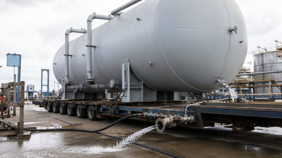
Drainage and drying is where schedules routinely bleed. A plain carbon steel vessel with no internal lining can drain and air-dry in one to two days. The same vessel with an epoxy or rubber lining, internal packing supports, or a full insulation jacket on the outside is a different problem entirely. Residual water trapped under insulation causes corrosion during transit; trapped water inside a catalyst bed or structured packing ruins the internal. Proper forced-air drying or nitrogen purge for insulated and internally coated vessels can add five to ten working days to the post-test sequence — a figure that frequently gets omitted from the vendor’s delivery commitment.
Drying time after hydrostatic testing is a contractual delivery milestone, not an informal shop activity.True
Trapped moisture in lined, coated, or insulated vessels can cause coating disbondment, corrosion under insulation, or contamination of process internals. Buyers should require drying certification as a hold point in the ITP before the vessel is released for shipment.
Pneumatic Testing: Approval Cycles Add Weeks, Not Days
Pneumatic testing looks faster on the surface — no water, no drying. In practice, the regulatory front-end consumes more calendar time than the test itself.
Before a single pound of pressure enters the vessel, the authorized inspection agency (AI) must review and approve a formal risk assessment. Depending on jurisdiction, vessel class, and how backed-up the AI’s schedule is, that approval cycle runs one to three weeks. If the risk assessment is submitted incomplete — missing material toughness data, a gap analysis against the applicable code, or the step-hold pressurization procedure — the clock resets.
The test day itself is longer than most planners expect. Step-hold pressurization under ASME UG-100 and equivalent code requirements means the operator pressurizes to a preliminary hold level, typically around 50% of test pressure, holds for a defined period, then increments upward in steps with visual inspection intervals. A pneumatic test on a medium-complexity vessel can run six to ten hours on the day, with the AI witness required throughout.
Post-test, the documentation package — risk assessment sign-off, step-hold pressure log, AI endorsement, and leak-detection records — must be reviewed and accepted before the vessel can be formally released. Budget two to five additional working days for that review cycle if the third-party inspector is coordinating across multiple projects.
Practical Scheduling Advice for EPC Buyers
Specify the test method in the data sheet at the inquiry stage, not during drawing review. Vendors price and schedule differently for the two methods, and a late change from hydrostatic to pneumatic — or vice versa — can shift the delivery date by two to four weeks while the risk assessment, inspector scheduling, and water management logistics are sorted out.
Tie test completion to a contractual milestone with liquidated damages linkage. “Ready for shipment” is too vague. The milestone should read: pressure test completed, AI-endorsed test record issued, post-test drying certificate (where applicable) accepted by the third-party inspector.
Align your third-party inspector’s schedule with the manufacturer’s planned test date a minimum of three weeks in advance. Inspectors working EPC projects carry dense travel schedules. A one-week notice is rarely sufficient, and a missed witness hold point means either a schedule delay or a waiver negotiation — neither of which costs nothing.
Vendor Evaluation Checklist: What Separates a Competent Pressure Test from a Paperwork Exercise
A pressure test certificate is easy to produce. A genuinely safe, code-compliant pressure test takes planning, calibrated equipment, qualified people, and a quality system that treats anomalies as data rather than inconveniences. When you are qualifying a fabricator or conducting a pre-delivery factory audit, the difference between these two situations is visible — if you know what to look for.
Equipment Verification: Gauges, Pumps, and Data Logging
Start with the test pump. Ask the manufacturer to show you the pump’s rated capacity in flow and maximum pressure output, and verify it matches the vessel’s test pressure requirement with adequate margin. A pump that barely reaches test pressure gives the operator no stable control window; pressure will oscillate, making leak detection unreliable and putting unnecessary cyclic stress on weld toes.
Pressure gauges are where superficial operations get caught fastest. Most major codes — ASME VIII UG-99, EN 13445-5, GB 150.4 — require at least two independent pressure gauges, each with a range of roughly 1.5× to 4× the intended test pressure. A gauge ranged too high loses resolution at the test reading; a gauge ranged too low risks going past full-scale deflection during pressurization. Inspect the calibration stickers on both gauges and cross-check the calibration certificate dates against the manufacturer’s own calibration interval policy. Certificates older than six to twelve months (depending on the facility’s documented program) are a flag worth raising.
Data logging is not universally mandated by code, but any serious fabricator will have it. A chart recorder or electronic logger gives you a time-stamped pressure trace that proves the vessel held test pressure for the full hold period — typically 30 minutes for hydrostatic tests under ASME, though duration varies by code and wall thickness. A handwritten logsheet filled in after the fact is not equivalent. Ask to see a sample completed test record from a recent vessel, not a template. The trace should show a gradual pressurization ramp, a stable plateau at test pressure, and a controlled bleed-down. Spiky or irregular traces deserve an explanation.
Personnel Qualification: Who Is Actually Running the Test
The pump operator needs documented qualification — not informal experience, but a traceable record within the manufacturer’s quality system. More critically, an Authorized Inspector (AI) or the equivalent third-party inspector must be present at the hold point. Verify the AI’s current credential: ASME AI commission, TÜV inspector certification, Lloyd’s Register survey status, or the relevant national body credential depending on your applicable code. These credentials have expiry dates and scope limitations. A fabricator who tells you the inspector “signed off remotely” or “will review the records afterward” is not meeting the intent of any major pressure vessel code.
A responsible engineer — typically the QC manager or a designated pressure vessel engineer — should also be present, not just reachable by phone. Their role is to make real-time decisions if something unexpected happens during pressurization.
Quality System Check: How Anomalies Are Handled
A manufacturer that has never recorded a pressure test anomaly or nonconformance likely has an incomplete quality system.True
In any realistic fabrication program, minor anomalies — slow gauge response, a weeping fitting, a temporary pressure drop — occur and must be documented and dispositioned. A completely clean record across dozens of vessels usually means anomalies are not being recorded, not that they never happen.
Pull two or three completed pressure test packages from the manufacturer’s records — ideally from vessels similar in pressure class and material to yours. Check that each package contains the signed test procedure, calibration records for all gauges, the time-stamped pressure chart, the AI hold-point sign-off, and the final release signature. Then look specifically for nonconformance reports. If a seam leaked or a gauge read inconsistently, there should be an NCR with a root cause, a corrective action, and a re-test record. Records that show only perfect outcomes, with no NCRs across a year of production, are a quality system problem, not a quality achievement. Whited-out entries, missing page numbers, or inconsistent date sequences are immediate audit findings.
The fabricator’s nonconformance control procedure should explicitly address test failures — defining who has authority to accept, reject, or authorize repair and re-test, and what customer notification is required. If that procedure exists only on paper and the production staff cannot describe it in conversation, treat it as non-functional.
Frequently Asked Questions About Hydrostatic and Pneumatic Testing for Pressure Vessels
Can a vessel pass the pneumatic test but still fail in service?
Yes, and this is one of the most underappreciated risks in pressure vessel acceptance. Pneumatic testing at 1.1–1.25× design pressure is effective at detecting gross through-wall leaks, but it is considerably less sensitive to tight weld defects — undercut, incomplete fusion, fine porosity chains — that may only open under sustained cyclic loading or corrosion in service.
Hydrostatic testing has a mechanical advantage here: the liquid medium probes weld discontinuities under load, and any visible weeping or sweating is immediately apparent during the hold period. Gas under pressure will not weep the same way. This is precisely why ASME Section VIII Div.1 UG-100 explicitly requires that any pneumatic-tested vessel compensate with enhanced NDE — typically 100% radiographic or ultrasonic examination of pressure-retaining welds — rather than the spot-RT that might be acceptable for a hydrostatically tested vessel.
The operational consequence is real. A vessel that leaves the factory with a marginal weld and only bubble-soap leak detection may enter service, pass initial commissioning, and develop a leak or structural issue months later when operating temperature cycles widen that defect. For EPC buyers, the practical takeaway is straightforward: if your vendor is proposing pneumatic testing, verify the NDE scope in the ITP before fabrication starts, not after.
Pneumatic testing at code-minimum pressure can miss tight weld defects that hydrostatic testing would reveal through visible weeping or pressure drop.True
Liquid-medium tests apply sustained hydrostatic load that opens fine discontinuities and produces visible leakage; gaseous medium at equivalent pressure stores energy elastically without the same defect-probing mechanism, making enhanced NDE mandatory to compensate.
Is a hydrostatic test required for all ASME pressure vessels?
Under ASME Section VIII Division 1, UG-99 establishes hydrostatic testing as the default acceptance test — not a preference, a default. The pneumatic alternative under UG-100 is only permissible when the vessel design or its supports cannot accommodate the weight of the liquid, when the process fluid is one that would be contaminated by water, or when the owner provides written authorization with a documented risk assessment accepted by the Authorized Inspector.
Outside the United States, the European Pressure Equipment Directive (PED 2014/68/EU) and harmonized standard EN 13445 follow equivalent logic: hydrostatic is the standard route, and the pneumatic alternative carries additional engineering justification requirements. Documentation expectations differ — PED requires a conformity assessment file rather than a National Board data report — so EPC buyers working on multinational projects need to confirm which code governs and what the jurisdictional authority will accept at final inspection.
What chloride limit applies to hydrotest water for stainless steel vessels?
Most codes and engineering standards, including ASME and common EPC project specifications, cite a maximum of 25–50 ppm chloride (Cl⁻) in hydrotest water for austenitic stainless steel grades such as 304 and 316. The actual limit applied by a given project specification may be tighter — some offshore and petrochemical specs call for ≤25 ppm, occasionally ≤10 ppm for high-alloy duplex materials.
The reason is chloride stress corrosion cracking (Cl-SCC), which can initiate in sensitized or strained weld heat-affected zones even during a brief water contact period if chloride concentration and temperature combine unfavorably. The vessel must be drained, flushed, and dried — by forced air or nitrogen purge — promptly after testing. Leaving standing water in a stainless vessel over a weekend is a documented cause of pitting that shows up during subsequent internal inspection.
Who is responsible if a vessel leaks after passing the factory pressure test?
Responsibility typically splits along workmanship versus design lines, and the third-party inspection certificate becomes the critical document in any dispute. The manufacturer carries responsibility for fabrication defects — improper weld procedure execution, incorrect filler metal, inadequate PWHT — that were present but undetected at the time of testing. If enhanced NDE was specified and performed, and the AI-certified test was witnessed and documented, the manufacturer’s workmanship warranty covers those defects.
The buyer and their engineering team carry responsibility for correct design inputs: operating pressure, temperature, corrosion allowance, nozzle loads. If a vessel leaks because the specified design pressure was understated at the inquiry stage, the factory test certificate does not shift that liability to the manufacturer.
In practice, the third-party inspector’s certificate and the stamped Manufacturer’s Data Report define the acceptance boundary. EPC procurement managers should treat these documents as legal instruments, not administrative paperwork, and ensure they are received and reviewed before the vessel ships.
Can the pressure test be waived for small or low-pressure vessels?
For new code-stamped fabrication, no — generally not. Neither ASME Section VIII nor EN 13445 permits waiver of the pressure test based on vessel size or maximum allowable working pressure alone. A 150 mm diameter vessel at 10 bar still requires a code-compliant pressure test if it carries an ASME or PED stamp.
The one context where alternative verification replaces a traditional pressure test is fitness-for-service assessment of existing equipment under API 579-1/ASME FFS-1, where in-service degradation has been assessed and a pressure test might cause more harm than benefit. That is a repair and re-rating scenario, not new fabrication. Any vendor suggesting a pressure test can simply be omitted from a new vessel to save time or cost should be asked to show the specific code paragraph that permits it — because that paragraph does not exist for stamped vessels.