
When an agitator and its reactor vessel are purchased from different suppliers, the mechanical interface must be defined before the affected vessel fabrication work is released. A motor rating, an agitator outline drawing and a nominal mounting flange size are not sufficient to establish the forces and moments that the vessel will experience.
For an industrial chemical reactor, buyers should request a controlled agitator load schedule that identifies the mounting interface, coordinate system, application point, static and dynamic reactions, operating cases, combination basis and applicable revisions. The assigned vessel designer must then assess those inputs against the actual vessel arrangement and project design requirements. The project must also identify who has authority to release the affected work.
This guide focuses on the transfer of mechanical loads between suppliers of complete industrial equipment, particularly when the agitation package and vessel are separately procured. It does not prescribe structural calculations, allowable loads, mixer sizing or operating procedures.
Why Agitator Loads Are a Vessel Fabrication Input
A top-mounted agitator may transfer its reactions through a mounting flange or pad into the reactor head, shell and supporting structure. Other installations may use separately supported drives, side-entry arrangements or additional internal bearings. The actual load path must therefore be established from the proposed configuration rather than inferred from the equipment name.
The rotating assembly has a static weight, but its mechanical interface may also experience axial thrust, lateral forces, torque and bending moments during operation. Fluid-induced forces can vary in magnitude and direction. A load transmitted through a baffle attachment or an internal steady bearing may act at a different location from the reaction at the main drive mounting.
The Chemineer Model 20 GT/HT vessel-mounting manual, Section F, illustrates this distinction for particular agitator models. It also refers users to the assembly drawing for mounting design loads. Its numerical mounting recommendations are specific to the equipment and assumptions described in that document; they should not be copied into a different reactor specification.
An acceptable process mixing prediction and an acceptable mechanical interface are separate outcomes. For high-viscosity applications, the guide to reactor mixing performance and motor rating explains the process-performance side of that distinction. Here the question is whether the vessel has been assessed using the correct mechanical reactions.
Identify the equipment boundary first
Before exchanging loads, confirm whether the vessel supports the entire drive assembly, whether part of its weight is carried by an independent structure, and whether the agitator includes additional supports inside the vessel. The approved arrangement should identify which components and attachment points belong to each supplier. A drawing showing the motor above the head does not necessarily establish what the head must carry.
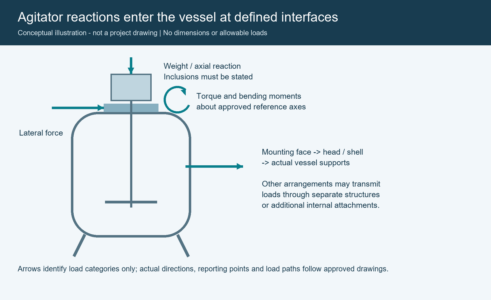
What Static and Dynamic Load Data Should the Agitator Supplier Provide?
Request reactions at the agreed mechanical interfaces, rather than only loads on the impeller or shaft. The originator should identify the actual arrangement and explain how the reported loads relate to that arrangement. Where more than one attachment transmits reactions, the schedule should distinguish the interfaces and identify which load sets are concurrent.
The following table is a procurement field guide, not a completed load specification. All quantities, limits and case definitions must come from the responsible project specialists.
| Load or interface input | Information to request | Why it matters to vessel review |
|---|---|---|
| Static assembly loads | Supported component masses or weights, centre of gravity, mounting arrangement, included and excluded items | Establishes which permanent loads are carried by the vessel and their offsets |
| Axial force | Magnitude, direction, case, and whether the reported reaction includes weight or other effects | Identifies axial demand at the relevant attachment without double counting |
| Transverse forces | Direction or defined directional envelope; case and application point | Identifies lateral demand and its relationship to mounting geometry |
| Torsional moment | Axis, sign, case, rating basis and any transient or dynamic contribution included | Distinguishes transmitted torque from drive rating |
| Bending moments | Components or documented resultant, reference point and concurrent forces | Defines overturning or bending demand at the interface |
| Repeated or time-varying loads | Description of amplitude/range, frequency content or other history, duration and cycles as required by the assigned assessment | Helps determine whether a static representation is adequate |
| Additional attachments | Baffles, internal bearings, independent support connections or other relevant interfaces | Identifies loads that may bypass the primary mounting flange |
| Mounting response criteria | Supplier-approved movement, tilt, alignment, stiffness or vibration requirements and their assessment basis, where applicable | Establishes compatibility between vessel support response and the agitation package |
Separate static-equivalent loads from dynamic information
A supplier may deliver a static-equivalent design reaction for a specified assessment, a range of operating reactions, or more detailed time-dependent information. Those deliverables are not interchangeable. Ask the originator to define the representation used and to identify any factors already applied. If additional dynamic evaluation is needed, the relevant specialists must agree on what information will support it.
In particular, a peak force alone does not describe how often it occurs or how the support system responds. Conversely, a cycle count with no associated load range or case information does not define repeated mechanical demand. Do not automatically require the same dynamic analysis for every vessel; determine the need through the applicable project design basis and qualified engineering review.
A published engineering discussion of impeller hydraulic forces explains the fluctuating nature of lateral fluid forces for particular mixing conditions. It is useful background for understanding why load characterization matters, not a source of universal reactions or design factors for a purchase order.
Do not count the same load twice
A mounting schedule may include a net vertical reaction, or it may list assembly weight and operating thrust separately. Likewise, a reported moment may already include the effect of an offset force. Ask the source to state its inclusions before incorporating the data into the vessel assessment. A separate gravity entry is not automatically an additional load to be applied on top of a net reaction.
Define the Loading Point, Axes and Geometry on the Same Drawing Revision
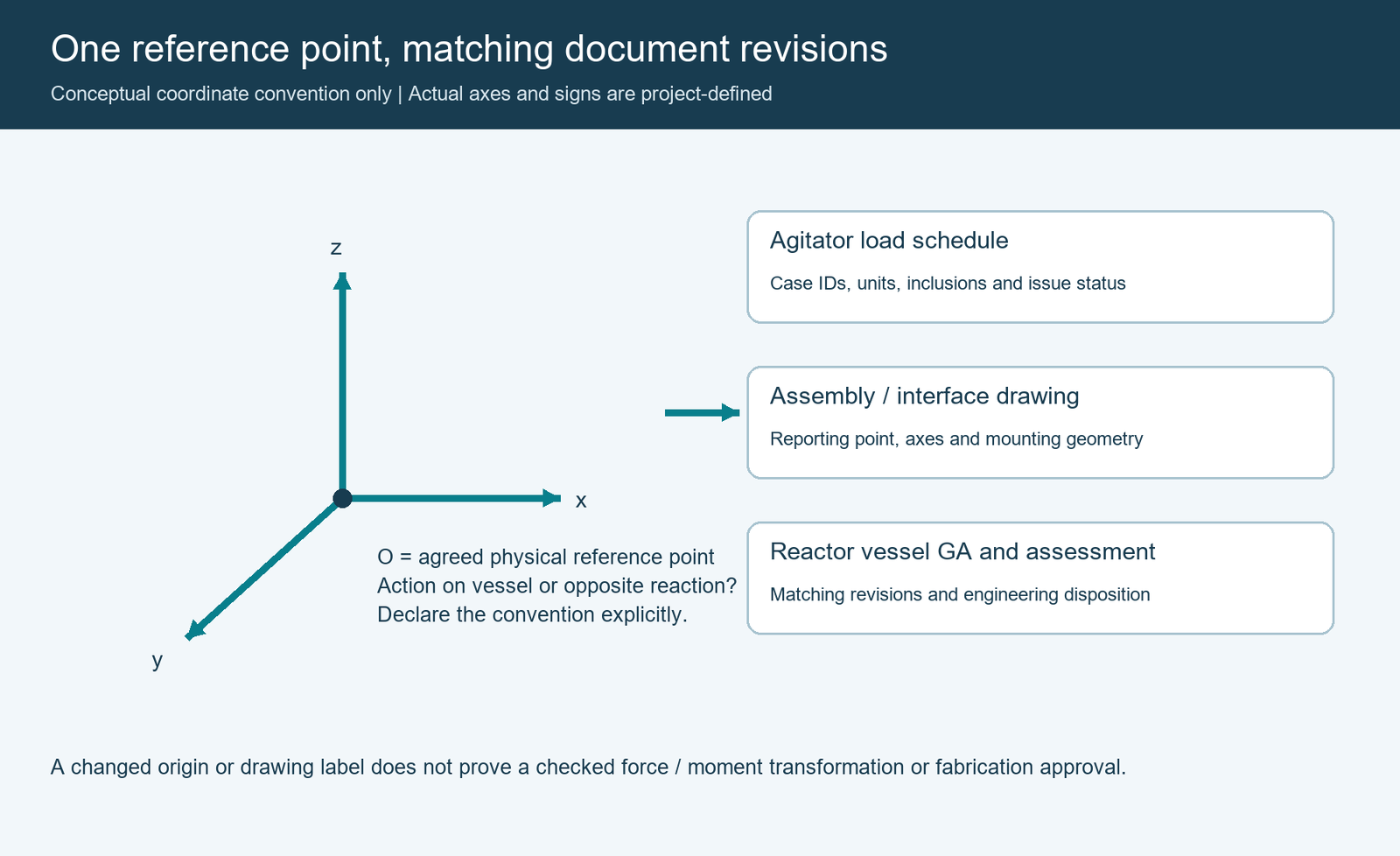
An agitator load schedule must be interpreted with the associated mechanical arrangement. A force at an impeller, a reaction at a bearing, and a force or moment at a vessel mounting face describe different locations. Even if the numerical force components are identical, transferring them to a different reporting point can change the moment that accompanies them.
The interface drawing should show the reference point and axes used by the load originator. The document should also state whether the reported values describe the action imposed on the vessel or the opposite reaction acting on the agitator. Sign conventions are important when the two suppliers use different models.
For a top-entry arrangement, one project might define a vertical axis through the agitator shaft and two transverse axes at the mounting face. That is an illustrative coordinate arrangement, not a mandatory convention. A different installation may need local and global coordinate systems with an explicitly documented relationship.
Confirm the following details together:
| Interface field | Required identification | Status |
|---|---|---|
| Equipment identity | Reactor and agitator tags; supplier assembly identification | TBC |
| Configuration | Mounting type, supported components, relevant secondary supports | TBC |
| Reference point | Physical point shown on drawing; location relative to mating face or other agreed datum | TBC |
| Coordinate convention | Axis directions, sign convention, local/global relationship, action or reaction convention | TBC |
| Units | Force, moment, mass or weight, displacement and other quantities clearly distinguished | TBC |
| Geometry basis | Assembly drawing, mounting details, shaft arrangement and vessel GA revision | TBC |
| Source | Originating load document number, revision, author and issue purpose | TBC |
TBC means to be confirmed. It does not mean zero or not applicable. The originator should explicitly identify cases or components that do not apply. Any required coordinate or reference-point transformation must be performed and checked by the responsible engineers; a revised spreadsheet heading is not evidence that the transformation has been completed.
General pipe-reaction conventions are addressed in the separate pressure vessel nozzle-load procurement guide. Agitator interfaces add machinery-specific concerns, including recurring reactions, mounting response, and the relationship between the rotating assembly and the vessel geometry.
Which Operating Cases Should Be Linked to the Agitator Load Schedule?
The process design team should define the permitted operating envelope and the agitation specialist should identify the conditions used to establish its reactions. Relevant inputs may include liquid level, density, viscosity or rheological description, solids or gas content, operating temperature, permitted shaft-speed range and the actual impeller arrangement. Pressure and temperature also affect the vessel’s concurrent design conditions.
Do not assume that the maximum motor rating, the highest liquid level or the final batch state always produces the controlling interface demand. Different load components may be governed by different operating conditions. The load supplier should explain which cases are applicable and which remain outside the evaluated envelope.
The project can use a register such as the following to connect the process cases to the corresponding mechanical inputs. These are candidate categories for discussion only; they are not a prescribed operating sequence or a claim that a particular reactor must evaluate every listed event.
| Case category | Process / equipment basis to establish | Load document and combination status |
|---|---|---|
| Normal permitted operation | Defined fluid state, working level, speed and vessel pressure/temperature | Case ID, reaction set and revision: TBC |
| Other permitted operating states | Relevant changes in process properties, inventory, speed or configuration | Case ID and basis: TBC |
| Agreed transient or occasional cases | Events identified by the project and assessed by the responsible specialists; applicable duration and concurrence | Required or not applicable; approved load set: TBC |
| Stationary or non-operating case | Actual supported weight, contents, assembly condition and relevant concurrent loads | Case and inclusions: TBC |
| Repeated service, where relevant | Operating history or design duty, cycles/ranges, frequency or other dynamic data needed for review | Assessment basis and source: TBC |
| Transport, erection or shop-test configuration, if relevant | Which components are installed, how they are supported and what separate loads apply | Separate approved case or exclusion: TBC |
Preserve simultaneous loading information
Suppose a supplier reports its greatest axial reaction under one condition and its greatest bending moment under another. Combining those two values in a single row does not establish that the two maxima occur together. An envelope can still be an approved design input, but its construction and permitted use must be explicitly defined.
The responsible engineers should decide whether the design basis uses actual concurrent load sets, a justified envelope or another representation. Preserve the source case identifiers, applicable signs, and any combination or scaling rules. Where multiple agitator attachments contribute to vessel loading, clarify their relationship to each other and other vessel loads.
The vessel designer must also know which operating pressure, temperature and other project loads accompany the agitator cases. Do not ask procurement personnel to construct code load combinations from individual vendor maxima. The appropriate combination method belongs to the assigned design specialists.
What Must the Vessel Designer Review Beyond Mounting Strength?
A mounting connection can have sufficient nominal strength yet still fail to satisfy a machinery interface requirement because its movement or rotation is not acceptable for the selected assembly. Mechanical integrity and compatibility with the agitation equipment should therefore both be addressed within the agreed engineering scope.
An agitated reactor review may involve the local mounting area, pressure boundary, attachment details, supporting structure, stiffness or movement, fatigue and dynamic behaviour, and the compatibility of the rotor and other machinery with the actual support conditions. The appropriate checks, methods and criteria depend on the design. Buyers should not impose a universal flange thickness, deflection limit, frequency separation or vibration threshold.
Where pressure-vessel construction rules apply, the project should specify the governing code, edition and jurisdiction. ASME BPVC Section VIII, Division 1 provides one widely used construction framework. Its official overview covers vessel design, fabrication, inspection and testing. The appropriate detailed code requirements and any supplementary machinery or dynamic assessments must be determined for the actual project, not inferred from the overview.
Request a traceable engineering disposition that identifies:
- The accepted agitator and vessel document revisions and assessed load cases.
- Which mounting interfaces, local regions, global supports and other load paths are included in the assessment.
- Which structural and machinery compatibility criteria apply, their origin and the party responsible for verification.
- Any additional analysis, assumptions, exclusions or restrictions that must be resolved before the relevant work is released.
- Any interface response information that must be returned to the agitator specialist for its own review, if required by the agreed design basis.
For example, a machinery supplier may request a defined mounting response from the vessel designer. Procurement should ensure that the response is delivered on the correct load and geometry basis and that the supplier records whether it is acceptable. A vessel design calculation alone does not automatically close the reciprocal machinery interface.
Which Revision Can Be Used to Release Reactor Vessel Fabrication?
The latest received document is not necessarily the latest approved document. Nor does a supplier’s issue of a drawing establish that the corresponding vessel assessment has been completed. The release decision should link the authorized load input, matching geometry, engineering acceptance and the specific work covered by the release.
A budgetary offer can be prepared on preliminary data if its assumptions and affected activities are clearly identified. If early production is proposed before the final agitation arrangement is available, the project must determine whether any defined interim design envelope can be accepted, which work it supports, and what must remain on hold. An interim envelope is not permission to proceed by default.
Use a release register to separate document submission from approval and work authorization:
| Deliverable | Evidence required | Suggested decision owner (confirm by contract) |
|---|---|---|
| Process case register | Controlled operating basis and approved applicable scenarios | Owner / EPC process team |
| Agitator arrangement and loading schedule | Matching revisions, load definitions, case IDs and issue status | Agitation supplier / assigned originator |
| Vessel assessment and interface response | Accepted inputs, methods, scope, conclusions and open items | Responsible vessel designer |
| Machinery compatibility disposition | Acceptance of relevant mounting response and agreed constraints | Assigned machinery specialist |
| Interface comment register | Resolved discrepancies or approved restrictions with responsible parties | EPC interface coordinator |
| Fabrication release record | Identifies released work, accepted revisions, applicable hold points and authorized signature | Project-designated release authority |
The project should define document status codes and whether approvals are internal, contractual or statutory. The table is a suggested coordination tool, not a code-prescribed approval chain. Approval by a purchaser does not remove responsibilities assigned by the governing code or regulatory framework.
Changes that may invalidate the release basis
A different drive arrangement, shaft length, impeller configuration, mounting elevation, support arrangement or process operating envelope can affect the previously assessed interface. Even a revision that changes only the reference point or clarifies whether weight was included can require reconciliation. The responsible specialists should determine the effects and issue a documented disposition before affected work proceeds.
A useful change record captures the old and new revisions, changed fields, affected vessel drawings or calculations, outstanding approvals and the authority for any renewed release. Keep superseded documents available for traceability but clearly identify the authorized baseline used in the shop.
For example, an EPC team might receive a final drive drawing after approving a preliminary vessel head arrangement. If the final drawing changes the supported weight or load reporting location, the document should be routed to the responsible vessel designer and machinery specialist. The fact that the bolt pattern still matches does not establish that the original mechanical assessment remains valid.
How Should Buyers Compare Quotations and Final Acceptance Scope?
When one bidder supplies only the fabricated reactor vessel and another includes the agitator, their prices may cover different interface engineering and verification tasks. Request a common scope breakdown so that exclusions become visible before an order is placed.
| Contract question | Evidence or deliverable to agree |
|---|---|
| Who supplies the final agitator load schedule? | Named originator; submission date; revision and approval process |
| Who performs the required vessel checks? | Scope of assessment, applicable basis and final calculation or review record |
| Who assesses machinery compatibility? | Required response criteria, verification deliverable and acceptance authority |
| Who supplies and verifies the interface geometry? | Approved mating drawings, specified tolerances and dimensional inspection scope |
| Who owns field integration and performance verification? | Battery limits, site responsibilities, agreed test conditions and accepted performance obligations |
| What happens when inputs change? | Change notification, affected-work control, engineering re-review and commercial disposition |
Inspection of the fabricated head, nozzle, attachments and relevant dimensions supports the agreed manufacturing acceptance. Pressure and leak testing, where required, provide evidence under their specified test conditions. They do not, on their own, demonstrate acceptable vibration, machine alignment under operating loads or the process mixing result.
Where the contract requires assembled-equipment testing or site verification, define its scope, conditions, acceptance criteria and witness responsibilities. A shop test conducted without representative process fluid may have a different purpose and evidentiary value from an agreed in-service performance demonstration. Do not assume that every test is included in a vessel-only quotation.
At handover, retain the approved loading basis, relevant vessel and machinery drawings, engineering dispositions, required inspection records, and any restrictions carried forward to installation or operation. Those records help establish whether a subsequent equipment change remains within the previously evaluated basis.
Frequently Asked Questions
Can motor rating replace an approved load schedule?
No. Rated power describes a drive capability under specified conditions, not the complete reactions at the vessel interfaces. Load data need to identify actual mounting arrangements, forces, moments and applicable cases, including relevant dynamic characteristics and inclusions.
Can the reactor head be released before final agitator data are received?
Only if the project-designated authorities have accepted a documented interim basis that explicitly covers that work and meets the applicable engineering requirements. Otherwise the affected work remains dependent on resolution of the critical loading and geometry inputs. A preliminary quotation or vendor drawing is not a fabrication approval.
Is a standard mounting flange sufficient to establish mechanical suitability?
No. Dimensional and pressure-rating compatibility does not by itself establish suitability for the actual forces, moments, repeated service or machinery mounting response. The appropriate assessment must cover the specific interface and project conditions.
Who approves an agitator load schedule when the vessel and agitator are bought separately?
The assigned load originator is responsible for its technical submission, while the vessel designer assesses the impact on its design. Machinery compatibility and overall interface closure must be allocated to the appropriate specialists and project authority. The contract and governing requirements determine the final approval route.
Prepare the Load Interface Before Ordering a Complete Chemical Reactor
Successful vessel fabrication begins with a defined mechanical interface, not with an assumed relationship between motor size and mounting loads. Supply the approved process cases, current agitator load schedule, assembly drawing and reactor vessel arrangement together. Ask the relevant parties to resolve conflicting revisions, define analysis deliverables and identify who authorizes the affected fabrication activities.
For a complete equipment enquiry, review WSHI’s industrial reactor pressure vessels and submit the available load and interface documents with a clear list of outstanding inputs. Confirm the actual vessel manufacturing, mechanical assessment, agitator integration and verification scope for the project before treating any of these activities as included.
References
- Chemineer / NOV. Model 20 GT/HT N Style Agitators, IOM Manual No. 731.02, February 2011, Section F and F.1, printed pages 10–11. Model-specific examples of mounting reactions and support assessment requirements; not a generic specification or source of universal acceptance limits.
- Gregory T. Benz. Agitator Impeller Hydraulic Force in Mixing Vessels, Chemical Engineering, November 1, 2025. Technical background on fluctuating lateral hydraulic forces; the article’s particular calculation assumptions and numerical examples are not adopted here.
- ASME. BPVC Section VIII, Rules for Construction of Pressure Vessels, Division 1. Official publication overview; project applicability and detailed requirements depend on the governing edition and jurisdiction.