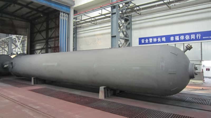

Unplanned turbine trips and burner flameouts rarely start with a catastrophic failure — they start with a slug of condensate that nobody planned for, or a pressure swing that the control valve couldn’t absorb fast enough. When fuel gas arrives at a combustion system carrying liquid hydrocarbons, compressor lube oil carryover, or pipeline corrosion products, the damage accumulates quietly: fouled fuel nozzles, accelerated tip erosion, unstable flame patterns, and eventually a forced shutdown that costs far more in lost production than the conditioning equipment ever would have. For facilities running continuous processes — power generation, petrochemical furnaces, glass melting, or cement kilns — even a four-hour unplanned outage can erase weeks of margin on a maintenance budget.
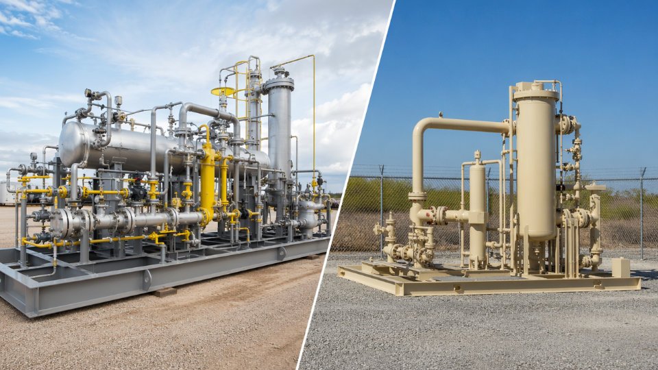
Fuel gas conditioning equipment is the engineered barrier between raw pipeline or process gas and the combustion system that depends on it. A complete skid typically handles pressure reduction from 0.5–10 MPa inlet down to the 0.1–2 MPa range required by burners or gas turbines, coalesces and removes liquid droplets down to 3 µm at efficiencies approaching 99.98%, and superheats the gas by 10–28°C above its hydrocarbon dew point to prevent condensate dropout at the point of use.
What makes this equipment worth examining carefully is that the design decisions — filter rating, superheat margin, pressure regulation architecture — are not interchangeable across applications. A natural gas-fired combined-cycle turbine has a completely different tolerance profile than a process heater on a refinery unit, and specifying one solution for the other is where procurement teams quietly introduce risk. The sections that follow break down each functional stage, the selection parameters that actually matter on the plant floor, and the failure modes that show up when those parameters are underspecified.
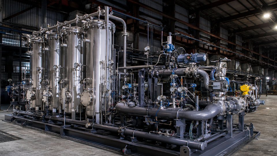
Fuel Gas Quality Specifications and the Conditioning Duty Case
Before a single piece of conditioning equipment can be sized, you need a complete analytical picture of the gas stream. Skipping this step — or relying on a generic pipeline specification without site-specific sampling — is the single most common root cause of coalescer flooding, turbine fouling, and chronic burner instability. The specification work is unglamorous, but it determines whether your conditioning skid is a reliable workhorse or an expensive bottleneck.
The Four Quality Axes That Drive Equipment Design
Hydrocarbon dew point is the first axis. This is the temperature at which heavy hydrocarbons begin to condense out of the gas phase, and it shifts with pressure. A gas that behaves cleanly at pipeline pressure can drop liquid at burner-tip conditions if pressure reduction is rapid and heat input is insufficient. Dew point surveys must cover the full operating pressure range — not just the nominal delivery pressure — because the worst-case condensation temperature often occurs at an intermediate pressure during a transient event such as a startup pressure ramp or a load shed.
Water dew point is distinct from hydrocarbon dew point and must be measured and treated separately. Water condensate corrodes carbon steel vessels, forms hydrates in the presence of light hydrocarbons, and carries dissolved salts that deposit on valve seats. Pipeline gas that meets a national gas quality tariff for water content can still produce free water inside a conditioning skid if inlet temperature drops below the water dew point during cold ambient conditions — a scenario that shows up frequently in winter commissioning.
Particulate loading — both particle size distribution and mass concentration — sets the filter specification. Gas turbine OEM requirements typically call for particles below 2 µm at concentrations under 0.1 mg/m³. Achieving that standard on a stream carrying pipe scale, mill scale, or weld slag from a recently commissioned pipeline demands staged filtration: a bulk separation stage to knock out gross liquid and large solids, followed by a high-efficiency coalescing element rated for the fine end of the size distribution. Trying to protect a turbine fuel control valve with a single filter element is a maintenance trap.
Contamination from upstream processing — compressor lube oil, glycol from dehydration units, amine carry-over from sweetening trains — represents the fourth axis. These contaminants are chemically distinct from natural condensate and require different removal mechanisms. Lube oil tends to coat coalescing filter media and degrade efficiency over time rather than appearing as a visible slug, which means you need upstream sampling protocol and replacement interval data, not just a one-time analysis.
Reading the Gas Chromatography Report and Dew Point Survey
A GC analysis gives you the molar composition, which feeds directly into a process simulation to generate a phase envelope — the pressure-temperature boundary across which two-phase behavior occurs. The critical output is the cricondentherm: the maximum temperature at which liquid can form regardless of pressure. For pipeline natural gas this typically falls between −5°C and +20°C depending on heavy-end fraction; for associated gas or rich off-gas it can easily exceed 30°C.
Plot the full phase envelope, then overlay your actual operating pressure range and the minimum expected inlet temperature. The gap between your operating conditions and the two-phase boundary is your safety margin. A minimum superheat of 10–28°C above the hydrocarbon dew point at the reduced delivery pressure is the accepted engineering practice, with the upper end of that range applied when flow rates are high, residence time in downstream pipework is short, or the end-use equipment is a gas turbine with tight contamination tolerances.
Pipeline Gas Versus Associated or Process Off-Gas: A Different Duty Entirely
Pipeline natural gas presents a conditioning duty that is relatively bounded. Composition is metered and contractually constrained, liquid loading is low under normal conditions, and flow is steady. You are essentially guarding against deviations from a known baseline — pressure transients, cold snaps, and the occasional pipeline maintenance event that disturbs accumulated sediment.
Associated gas and process off-gas are a different problem class. Composition varies with well production rates, reservoir pressure decline, and upstream separator performance. Heavy hydrocarbons (C₆+) appear in concentrations that can double or triple during a slug event. H₂S and CO₂ concentrations may fluctuate, affecting both materials selection for pressure-containing components and downstream combustion stoichiometry. Slug flow — alternating liquid and gas phases arriving at the conditioning skid inlet — can overwhelm a vessel sized only for steady-state liquid rates.
A coalescing filter-separator operating under API 12J service conditions can achieve 99.98% removal efficiency for liquid droplets at 3 µm and above.True
This efficiency benchmark is consistent with API 12J and ISO 3977 service condition ratings for properly sized and maintained coalescing filter-separators; actual field efficiency depends on inlet liquid loading staying within the vessel's design envelope and filter elements being replaced on schedule.
Building the Duty Case Document
The duty case is not a datasheet — it is a structured narrative that defines the full operating envelope the conditioning system must survive and perform within. It must include normal flow rate with expected composition, turndown flow (typically 25–40% of design, depending on the combustion process), and peak or upset flow that the system must pass without failing safe. Inlet temperature envelope — minimum, maximum, and the rate of change during startup — drives both material selection and heat input sizing. Worst-case liquid fraction defines separator vessel diameter and coalescing element area.
This document becomes the primary technical input to any vendor inquiry package. Without it, vendors will quote to assumed conditions that may not match your site, and you will only discover the mismatch during commissioning — when changing out an undersized vessel carries a very different price tag than getting the specification right upfront.
Pressure Regulation and Control Valve Stations: Sizing, Redundancy, and Slam-Shut Architecture
The pressure control station is where gas conditioning theory meets combustion reality. Get it wrong and you face either an under-pressured burner that trips on flame failure, or an over-pressured header that lifts a relief valve at the worst possible moment. The equipment choices here — regulator type, redundancy topology, slam-shut logic — have direct consequences on turbine availability, boiler efficiency, and site safety classification.
Self-Operated Regulators Versus Control Valve Configurations
Self-operated regulators — whether spring-loaded direct-acting or pilot-operated — are mechanically elegant: no instrument air, no positioner, no DCS loop required. A pilot-operated unit can hold outlet pressure within roughly ±1–3% of set point across a rangeability of 20:1 to 50:1, depending on pilot sensitivity and seat design. Response to demand transients is typically 0.5–2 seconds, fast enough for steady burner loads but marginal for combustion turbines with fast-acting fuel control valves that demand pressure excursions held within ±0.2 bar.
Control valve plus positioner configurations answer that demand. A well-tuned electro-pneumatic positioner with a digital valve controller can respond in under 200 milliseconds and achieve rangeability up to 100:1 — essential when a plant gas header must simultaneously serve a 40 MW turbine at base load and a pilot burner at 2% capacity. The trade-off is instrument air dependency, DCS integration, and higher installed cost. Noise generation increases sharply at high pressure-drop ratios; without cage trim or outlet diffusers, a control valve dropping 3–5 MPa can generate aerodynamic noise exceeding 110 dB(A) at 1 metre, requiring either anti-cavitation trim or in-line silencers sized per IEC 60534-8-3 methodology.
Monitor-Active and Working-Monitor Redundancy
EN 12186 and ANSI/ISA 75 both recognise two dominant series redundancy architectures. In a monitor-active arrangement, two regulators run in series: the active regulator controls to the target delivery pressure, while the monitor regulator is set approximately 10–15% higher. If the active unit fails open, the monitor takes control before downstream pressure exceeds the burner specification. This architecture suits high-consequence services — gas turbine fuel systems, fired heater headers above 1 MW thermal duty — where any uncontrolled pressure excursion causes immediate equipment damage.
Working-monitor in parallel (sometimes called duty-standby) instead routes flow through one leg while the second sits pressurised and ready. Switchover is either manual or automatic on deviation. OEM turbine packages frequently mandate series monitor-active topology as a condition of their fuel system warranty; verify this in the turbine TIL documents before finalising the P&ID.
Slam-Shut Valve Architecture and Set-Point Logic
A slam-shut valve (SSV) is not a control device — it is a last-resort mechanical isolator. Standard set-point practice places the overpressure trip at 110–120% of maximum allowable working pressure downstream, and an underpressure trip at 60–80% of minimum stable burner operating pressure. The underpressure trip is frequently overlooked during commissioning; a pressure collapse from a ruptured expansion joint upstream will extinguish a flame faster than the burner management system reacts, leaving unburned fuel in a hot firebox.
Mechanical reset SSVs require a technician to physically reset and verify the valve, which adds a deliberate human checkpoint after any trip. Solenoid-actuated reset allows remote reinstatement from the control room, which suits unmanned compression stations but requires a robust proof-test programme — typically every 3–6 months — to confirm the solenoid actually holds against working pressure. Partial-stroke testing capability on larger SSVs (DN100 and above) reduces proof-test risk by avoiding full closure in live service.
Cv, Cg Calculations, and Material Compliance
Sizing a gas service control valve on liquid Cv alone is an error that generates significant control instability. Gas flow uses the Cg (or Cv with expansion factor Y and specific gravity correction) methodology. At pressure ratios above the critical threshold — typically P2/P1 below 0.53 for most diatomic gases — flow chokes at the vena contracta regardless of further outlet pressure reduction. Oversizing under choked conditions produces a valve operating at 10–20% travel, where hysteresis, packing friction, and seat wear are worst.
NACE MR0175 / ISO 15156 compliance is mandatory for any wetted metallic component in gas streams containing more than 0.0003 MPa partial pressure of H2STrue
This threshold is defined in ISO 15156-1 and applies to carbon steel, low-alloy steel, and certain stainless grades; exceeding it without compliant material selection risks sulfide stress cracking failures that can occur within weeks of commissioning
For sour gas services, valve body and trim selection shifts to 316L stainless or Duplex 2205 for moderate H2S levels, with Alloy 625 or Hastelloy C-276 trim reserved for high partial-pressure or chloride-combined environments. Specify hardness limits — typically HRC 22 maximum for carbon and low-alloy steels — and require material test reports traceable to heat number.
Joule-Thomson Cooling and Winterization
A regulator or control valve dropping 2–5 MPa of natural gas pressure generates a Joule-Thomson temperature reduction of roughly 20–40°C, the exact figure depending on inlet temperature, gas composition, and pressure ratio. In a temperate climate this turns a 15°C inlet stream into a sub-zero outlet. Carbon steel loses impact toughness below –20°C; condensate and hydrates begin forming at temperatures near the hydrocarbon dew point, fouling downstream trim seats within days.
The practical mitigation hierarchy: upstream indirect-fired or electric heaters to raise gas temperature before the letdown station, heat tracing with mineral-insulated cables on the valve body and immediate downstream piping, and thermal insulation with vapour barrier. For remote or arctic installations where power is limited, a regenerative heat exchanger recovering waste heat from the compressor aftercooler sometimes provides adequate preheat without additional fuel consumption. Design the heat duty around worst-case ambient and flow conditions, not average annual values.
Filter-Separators and Coalescing Elements: Liquid and Particulate Removal Equipment Selection
Filtration and separation are where most fuel gas conditioning failures originate — not at the pressure regulator or the slam-shut valve, but upstream, when liquid slugs or fine aerosols reach equipment that was never designed to handle them. Selecting the right separation train requires understanding not just what particles and droplets are present, but at what flow velocity, pressure, and slug frequency they arrive.
Three-Stage Separation in Series: Why Each Stage Has a Distinct Duty
A well-designed conditioning system uses three stages in series rather than relying on a single high-efficiency vessel to do everything.
The first stage is an inlet cyclone or centrifugal pre-separator. Its job is bulk liquid removal — slugs, free water, and entrained liquid volumes that can arrive as a wave during pigging operations or after hydrate inhibitor injection upsets. These units separate by centrifugal momentum, not filtration, so they handle high liquid loadings without blinding. Typical separation efficiency for droplets above 100 µm is high, but they pass aerosols and mist essentially untouched. Sizing depends on gas throughput and the anticipated worst-case slug volume; vessels undersized for slug surge will carry liquid forward into the coalescing stage and shorten element life dramatically.
The second stage is the coalescing filter vessel. This is where fine aerosols and hydrocarbon mist in the 3–10 µm range are captured. Coalescing elements work by forcing the gas stream through a fibrous matrix where small droplets impinge, coalesce into larger ones, and drain by gravity to the sump. Element fiber material matters: borosilicate glass fiber handles higher temperature service and resists most hydrocarbon solvents, while polyester elements are appropriate for lower-pressure, ambient-temperature duty where cost is a driver. The critical selection parameter for turbine protection is the beta ratio — specify β₃ ≥ 200, meaning fewer than one droplet per 200 inlet droplets at 3 µm passes through. Anything below that benchmark leaves compressor blades and fuel nozzles exposed to fouling deposits over an operational season.
The third stage is a final barrier filter for sub-micron particulates, catalyst fines, pipe scale, and any fiber shedding from upstream elements. This is a solid-particle filter, typically rated at 0.5–1 µm absolute, installed as the last line of defense before the metering station or burner train.
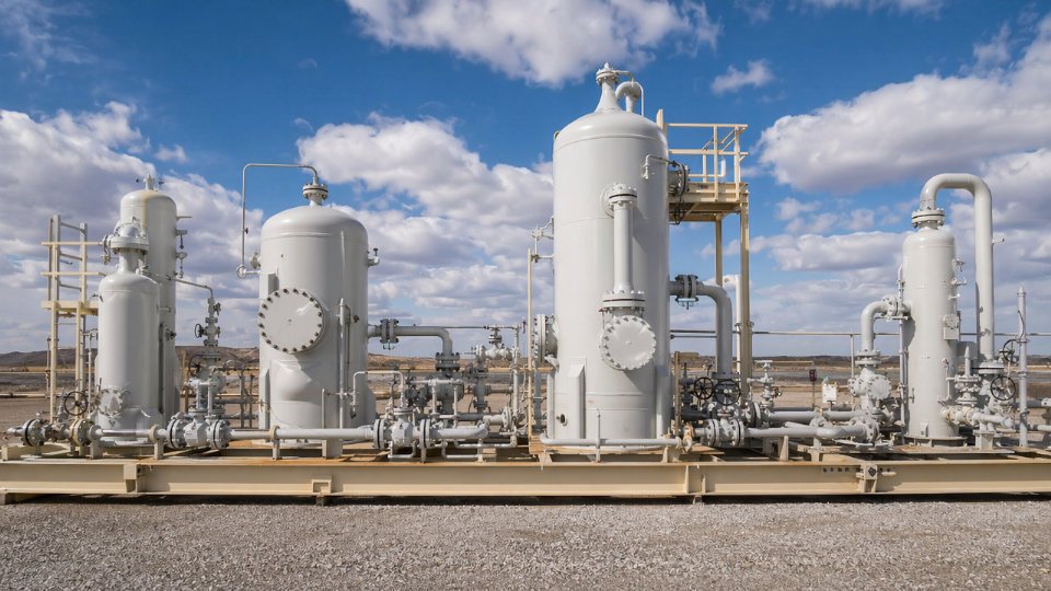
Coalescing Vessel Sizing: API 12J and GPSA Parameters
Vessel sizing follows API 12J and the GPSA Engineering Data Book methodology. The key parameters are: gas inlet velocity through the coalescing matrix (typically 0.03–0.08 m/s superficial velocity depending on element design — exceeding this carries re-entrained liquid forward rather than draining it), liquid retention volume between drain cycles (sized for 10–30 minutes accumulation at maximum design liquid loading), and surge volume to absorb a worst-case slug without flooding the element bundle. Nozzle sizing for gas inlet and outlet, liquid drain, and vent connections follows from these volumes; undersized drain nozzles are a common oversight that causes sump backup during high liquid events.
Automatic Drain Systems: Comparing Options for Remote Installations
Three drain system types are common, each with different failure behavior. Float-operated mechanical drains are simple and require no instrument air or power, but float mechanisms corrode or stick in sour or dirty service — a stuck-open float drains gas continuously; a stuck-closed float floods the vessel. Timer-controlled pneumatic drains open on a fixed cycle regardless of actual liquid level, which works acceptably where liquid loading is predictable but wastes gas when conditions vary. Electronically actuated drains with level transmitters are the most reliable option for unmanned or remote installations, provided the level instrument is correctly specified for the liquid density and dielectric properties of the condensate involved.
Coalescing filter elements in natural gas service should be replaced based on differential pressure rise, not calendar time alone.True
Liquid loading rate, inlet gas quality, and slug frequency vary significantly between installations. An element in clean, dry service may reach 12,000 hours without significant ΔP rise, while the same element in high-condensate or inhibitor-contaminated service may blind within 2,000–3,000 hours. Using calendar replacement alone risks either premature replacement cost or missed blinding events.
Inspection and Replacement Triggers
Replace coalescing elements when differential pressure across the vessel rises 35–50 kPa above the clean baseline reading taken at commissioning — not from a generic table, but from that specific skid at its actual operating flow. This range reflects the spread across element designs and vessel geometries; the element manufacturer’s published limit takes precedence where it falls within this band. Scheduled replacement regardless of ΔP is appropriate as a maximum interval, typically 8,000–12,000 operating hours depending on service severity. On element removal, inspect for media discoloration, fiber compaction at the upstream face, and sealing surface condition on both end caps — a bypassed end seal is invisible to the ΔP gauge and is the most common reason a coalescing stage fails silently while the instrument reads normal.
Fuel Gas Heaters and Superheating: Heat Exchanger Type Selection and Thermal Sizing
Condensate dropout at a turbine combustion nozzle is not a minor nuisance. Liquid hydrocarbon droplets carried at velocity into a fuel nozzle cause localized thermal shock, accelerate tip erosion, and destabilize flame geometry — the downstream consequence being NOx excursions that trigger environmental permit violations and, in severe cases, hot-section damage requiring unplanned outage. Most gas turbine OEMs specify a minimum superheat margin of 10–28°C above the hydrocarbon dew point measured at the turbine fuel gas connection flange, not at the skid outlet. That distinction matters: if the interconnecting pipework runs outdoors in a cold climate, the gas can lose 5–12°C between the skid and the turbine depending on pipe diameter, insulation quality, and ambient conditions. Size the heater for the connection point, not the skid outlet temperature.
Gas turbine OEMs mandate minimum superheat above the hydrocarbon dew point at the fuel gas connection to prevent condensate-induced combustion nozzle damageTrue
This is a standard requirement documented in turbine fuel gas specification documents from major OEM packages; the exact margin varies by frame size and fuel composition but typically falls in the 10–28°C range above the calculated hydrocarbon dew point.
Matching Heat Source to Site Infrastructure
The available heat medium dictates heater type before thermal duty calculations even begin. Hot water from a heat recovery steam generator condensate loop or engine jacket cooling circuits is the cleanest solution where available — low-pressure, easy to control, and inherently limited in maximum temperature, which reduces the risk of local overheating on the gas side. LP steam at 0.3–1.0 MPa is the most common heat medium on gas processing and power generation sites; it offers a predictable condensing duty, tight temperature control through a simple pressure regulator, and high heat flux in a compact exchanger. Electric immersion heaters suit low-flow applications — instrument gas, pilot fuel lines, or cold-start duty — where electrical infrastructure is already present and thermal load is under roughly 50–150 kW depending on site constraints. Direct-fired systems become the practical choice for remote compressor stations or wellhead sites where neither steam nor reliable grid power exists.
Shell-and-Tube Design Choices for Gas Service
For steam or hot-water-heated applications, shell-and-tube exchangers remain the default. TEMA BEU (U-tube bundle, bonnet front, externally sealed rear) handles differential thermal expansion without bellows and allows bundle pull for inspection — the right choice when the gas carries any trace of heavier hydrocarbons that can deposit on tube surfaces. TEMA BEM is acceptable for clean sweet gas at moderate temperatures but offers no expansion relief, so carbon steel construction requires careful attention to thermal growth at flanged connections. Route gas on the tube side when fouling is the primary concern; tube-side cleaning is straightforward. Route gas on the shell side only when pressure drop budget is tight and the gas is demonstrably clean, since shell-side deposits are harder to access without bundle removal.
Direct-Fired Indirect Heaters for Remote High-Flow Duty
Water bath indirect-fired heaters (IFH) built to ASME Section VIII are the standard answer for remote high-flow gas heating. The coil or bundle sits submerged in a heated water bath, keeping the flame separated from the process gas and providing a thermal buffer that prevents hot spots. Burner management systems on these units must comply with NFPA 86 minimum requirements: proved pilot, flame scanning, high-bath-temperature shutdown, and automatic gas valve sequencing. Separation distance from process equipment and ignition sources should be confirmed against site-specific hazardous area classification — typically 15 metres or more from classified zones depending on local code and hazard inventory.
Material Selection for Sour and Chloride-Containing Gas
Carbon steel is entirely adequate for sweet natural gas service above 0°C metal temperature and below 50 ppm H2S partial pressure. Once H2S wet-sour conditions exist — even episodically during startup — NACE MR0175/ISO 15156 compliance governs all wetted metallic components, which in practice means hardness control on welds and heat-affected zones, and often mandates low-alloy or austenitic grades. Where chloride contamination is possible, 316L stainless steel is the minimum for tube bundles; duplex grades such as 2205 provide higher resistance to stress corrosion cracking under combined chloride and H2S exposure, though weld procedure qualification and PWHT requirements add cost and schedule time that must be budgeted at the inquiry stage.
Skid Integration, Piping Layout, and Instrumentation Architecture for Conditioning Packages
A fuel gas conditioning skid is only as reliable as its integration layer. Individual components — filter-separators, regulators, heaters — can each meet their datasheet specs in isolation and still deliver poor field performance if the piping geometry re-entrains liquids, if the instrumentation architecture can’t vote out a failed transmitter, or if the documentation package fails a notified body audit six weeks before commissioning. EPC project engineers evaluating vendor proposals need to look past the P&ID and assess the fabrication and systems engineering competence behind it.
Scope Boundary and Baseframe Philosophy
The standard scope boundary for a packaged conditioning skid runs from the inlet isolation valve — typically a full-bore ball valve with locking device — through inlet filter-separator, pressure regulation station, gas heater, flow metering, and outlet isolation valve, terminating at the turbine or burner flange connection. All interconnecting piping within this boundary is ASME B31.3 process piping, fabricated and hydrostatically tested as part of the skid before shipment. Everything sits on a single structural steel baseframe, hot-dip galvanized or epoxy-primed depending on site exposure class.
The single-baseframe discipline matters operationally. Split skids that arrive as loose components force field piping between modules, which introduces field welds outside the vendor’s quality system, undefined stress analysis ownership, and commissioning delays of weeks rather than days. Get the vendor to confirm the maximum baseframe dimension their fabrication shop can handle — typically 12–18 m in length before transport constraints take over — and verify that their heaviest lift falls within the site crane capacity. These are conversations worth having at the RFQ stage, not during FAT.
Piping Layout and Liquid Management
Gas conditioning piping layout decisions have direct consequences for liquid carryover. Flow should travel in a consistent direction through the skid — from inlet isolation through the separator, then forward through the heater to the metering station — without direction reversals that can collect condensate in dead legs. Horizontal pipe runs require a minimum gravity-drain slope of 1:100 toward designated low-point drain valves. Any run flatter than this will pond condensate during low-flow or startup conditions, and that liquid will eventually carry forward in slugs.
High-point vents are mandatory at every topographic high point in the system, and low-point drain valves must be accessible without confined-space entry. Access clearances around all control valves should not be less than 750 mm on the actuator side — tighter clearances get valve maintenance deferred, and deferred maintenance on a pressure-regulating valve is how a turbine combustor gets overpressured during a setpoint drift event.
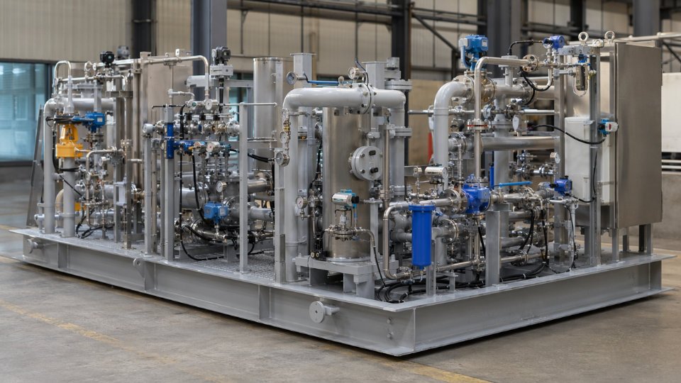
Instrumentation Architecture and Control Integration
For critical pressure regulation loops, a 2oo3 (two-out-of-three) voting architecture on pressure transmitters is the correct answer. A single transmitter per loop is inadequate for turbine fuel gas service; a failed transmitter causes either a spurious trip or undetected overpressure depending on failure mode. Temperature elements must be installed with thermowells sized per ASME PTC 19.3 — insertion depth typically 50–75% of pipe internal diameter, with a wake frequency calculation documented for any line above DN50 to avoid thermowell fatigue failure from vortex shedding.
Differential pressure switches across filter vessels provide the primary indication that elements are loading and approaching change-out interval. Position feedback on all automated valves — open/closed limit switches as a minimum, analog position feedback on modulating valves — feeds the turbine control system via 4–20 mA HART or Foundation Fieldbus, depending on the plant DCS architecture. Confirm the protocol at the instrument index stage, not during loop checks.
Materials Documentation and Weld Quality Requirements
Every pressure-containing component on the skid — pipe, fittings, flanges, vessel shells — requires a mill test report (MTR) traceable to the heat number. For alloy piping, typically 316L stainless or Duplex 2205 in sour gas service, positive material identification (PMI) using X-ray fluorescence is performed on 100% of alloy welds and fittings, with results documented in the inspection dossier. Weld procedure specifications (WPS) and procedure qualification records (PQR) must comply with ASME Section IX, and all welders working on pressure-containing joints must be qualified to those procedures.
Hydrostatic testing at 1.5× design pressure, held for a minimum of 30 minutes with no visible leakage or pressure drop, is performed on the fully assembled skid before shipment. The test medium is clean water, inhibited if the piping is carbon steel. Pneumatic testing as a substitute requires specific engineering justification and additional safety controls — it is not a default equivalent.
Regulatory Compliance for Multi-Jurisdiction Projects
CE marking under PED 2014/68/EU is mandatory for pressure vessels and piping assemblies placed on the market in EU member states, regardless of where they are fabricated.True
PED 2014/68/EU applies to pressure equipment with maximum allowable pressure above 0.5 bar placed on the EU market. Fabrication outside the EU does not exempt the equipment; the manufacturer or EU-based responsible person must ensure conformity and affix CE marking with a notified body involved for Category III or IV equipment.
For vessels within the skid scope, ASME U-stamp certification remains the baseline for North American projects and is widely accepted by engineering companies globally as evidence of fabrication quality oversight. Canadian projects add CRN (Canadian Registration Number) registration, which is province-specific — a vessel registered in Alberta carries a different CRN than the same vessel registered in British Columbia. EPC buyers assembling vendor shortlists for multi-jurisdiction projects should ask vendors to confirm which notified bodies and authorized inspection agencies they hold active relationships with, and which provinces they have active CRN registrations in. These are not administrative afterthoughts; they sit directly on the critical path between factory acceptance test and project mechanical completion.
Custody Transfer and Fiscal Metering Integration Within Conditioning Systems
Conditioning skids built purely for combustion flow control and those configured for fiscal-quality allocation metering look superficially similar on a P&ID but carry fundamentally different documentation, calibration, and certification burdens. Getting this distinction wrong at the specification stage is one of the more expensive procurement mistakes on a gas turbine project — discovered late, it forces schedule-busting rework after the skid has already passed factory acceptance.
When Combined FRM Skid Architecture Is Required
For independent power producers and utilities purchasing gas under a tolling or wheeling arrangement, the supplier and offtaker typically settle commercially on energy delivered, not just volume flow. That billing relationship demands fiscal-quality allocation metering integrated with the same package that handles pressure regulation and liquid dropout protection. A filter-regulator-meter (FRM) skid consolidates these functions: the gas arrives at high inlet pressure (commonly 3–7 MPa on a pipeline lateral feeding a gas turbine), passes through coalescing filtration, is regulated to the combustion system’s fuel gas header pressure (typically 1.5–4 MPa depending on turbine inlet specification), and is then metered at a stable, conditioned condition before the burner manifold. Co-location is not merely convenient — it ensures the metering element sees gas that has already been cleaned and thermally stabilized, which directly affects measurement uncertainty.
Comparing Metering Technologies in Fuel Gas Service
Ultrasonic meters operating to AGA Report No. 9 custody transfer grade achieve measurement uncertainty in the range of ±0.2–0.5% at reference conditions; the tighter end of that range depends on achieving a minimum Reynolds number, correct upstream straight-run lengths (typically 10–20 pipe diameters depending on fitting configuration), and valid acoustic path diagnostics. They have no moving parts and tolerate the moderate liquid carryover risk remaining after coalescing filtration better than turbine meters do.
Orifice plate metering runs per AGA Report No. 3 and ISO 5167 remain the most widely accepted approach in legacy power plant installations and in jurisdictions where the regulatory body still mandates a differential-pressure primary element for legal-for-trade gas measurement. Uncertainty is typically ±0.5–1.0% and depends heavily on bore condition, beta ratio selection, and the differential pressure transmitter calibration interval. Plate wear and contamination in dirty gas service will move that number toward the worse end faster than most plant operators budget for.
Coriolis meters suit low-flow, high-accuracy applications — pilot burner fuel lines, fuel gas to small auxiliary boilers — where line sizes below DN 50 make orifice plates impractical and ultrasonic meters lose performance. Achieved uncertainty of ±0.1–0.15% is realistic under stable conditions; sensitivity to vibration and the need for periodic density verification are the operational constraints to manage.
Flow Computer and Gas Chromatograph Integration
Real-time energy metering in MJ/h or MMBtu/h requires continuous composition input. A process gas chromatograph running a C6+ analysis cycle every 3–5 minutes feeds calorific value and relative density data to the flow computer via a Modbus or HART link. The interface between these two instruments must be validated — not just wired and tested for signal integrity — for custody transfer traceability. That means the flow computer’s calculation engine must be certified to AGA Report No. 7 or equivalent, the chromatograph must carry a calibration certificate traceable to a recognized national metrology institute, and the combined system uncertainty budget must account for the composition update latency during rapid flow transients.
A gas chromatograph cycle time of 3–5 minutes is acceptable for custody transfer energy metering in steady-state turbine fuel gas serviceTrue
AGA-9 and ISO 17089 both permit composition update intervals of this duration for steady-state pipeline or turbine fuel gas service, provided the flow computer interpolates between updates and the gas composition is not highly variable. Where gas quality swings rapidly — LNG send-out or mixed pipeline supply — shorter cycle times or online Wobbe index analyzers are specified alongside the GC.
Proving, Calibration, and In-Situ Diagnostics
Ultrasonic meters support in-situ diagnostic checks — velocity of sound comparison across paths, gain ratios, signal-to-noise ratios — that provide ongoing confidence without removing the meter from service. These diagnostics do not substitute for periodic calibration but they do allow anomaly detection between scheduled proving intervals, which typically run every 1–3 years depending on the commercial agreement.
For onsite verification, a portable transfer standard prover calibrated against a NIST-, PTB-, or NPL-traceable reference is brought to the skid location. The comparison run generates a correction factor that adjusts the meter factor in the flow computer. Any shift greater than ±0.25% from the previous proven meter factor should trigger root-cause investigation before the new factor is accepted.
Documentation Requirements That Distinguish Fiscal Metering Skids
Standard process skids ship with a material dossier and an instrument calibration record. Fiscal metering packages require significantly more. OIML R 137 certification (or NTEP approval for North American legal-for-trade applications) must be confirmed before the skid design is frozen because both frameworks impose constraints on enclosure design, tamper evidence, and audit trail logging that are expensive to retrofit. Third-party witnessed factory acceptance testing with a traceable flow-loop calibration — not a bench calibration of individual instruments — is non-negotiable for most utility contracts. The as-built uncertainty budget per ISO/IEC Guide 98-3 (the GUM) documents every contributing uncertainty source from the primary element through the flow computer output and must be delivered as a living document that gets updated after any component replacement.
Procurement teams that treat the metering portion of an FRM skid as an add-on instrumentation scope, rather than a primary deliverable with its own quality plan and hold points, tend to discover the gap at commissioning when the gas supplier’s fiscal metering agent arrives and finds the documentation package incomplete.
Material Selection, Corrosion Allowance, and Pressure Vessel Code Compliance for Fuel Gas Service
Getting the materials wrong on a fuel gas conditioning vessel is not a specification inconvenience — it is a pathway to accelerated wall loss, weld cracking, or a failed hydrostatic test at the worst possible point in a project schedule. The material decision tree starts with the gas chemistry, then the operating temperature envelope, then the regulatory code jurisdiction, in that order.
Baseline Material Matrix for Carbon Steel and Low-Temperature Service
For sweet natural gas service above 0°C, ASTM A106 Grade B seamless pipe and ASTM A516 Grade 70 plate remain the workhorses of filter-separator shells, inlet piping, and pressure regulator body assemblies. Both are well-characterized under ASME Section VIII Division 1, readily available across most fabrication markets, and straightforward to weld with qualified procedures. Where the process drops below 0°C — which happens regularly on high-pressure letdown stations where Joule-Thomson cooling can drive temperatures to -20°C or lower depending on inlet pressure and flow rate — ASTM A333 Grade 6 seamless pipe and ASTM A420 WPL6 fittings are specified for impact toughness down to -46°C. Skipping this substitution because “the ambient temperature is warm” is a documented source of brittle fracture events on uninsulated letdown legs in northern climates. Do not conflate process temperature with ambient temperature; calculate the JT cooling at maximum flow before signing off on the carbon steel BOM.
Sour and Chloride Service: When Corrosion Allowance Stops Being the Answer
Adding millimeters of corrosion allowance to a carbon steel vessel works when the corrosion mechanism is uniform and predictable. In H2S sour service, the mechanism is sulfide stress cracking (SSC) and hydrogen-induced cracking (HIC), neither of which responds to wall thickness. NACE SP0472 and NACE MR0175/ISO 15156 define the H2S partial pressure thresholds above which carbon steel — regardless of thickness — requires hardness control, HIC-tested plate, and sometimes full alloy substitution. For gas streams carrying chlorides alongside H2S, SA-240 316L stainless or UNS S31803 duplex stainless are specified for wetted internals, coalescing element housings, and nozzle bores at minimum. Solid duplex or CRA-clad carbon steel shell construction is the practical approach for sour separator vessels rather than assigning a nominal corrosion allowance that provides no protection against the actual failure mode.
Corrosion allowance alone is sufficient protection for H2S sour service pressure vesselsFalse
H2S sour service failures occur via sulfide stress cracking and hydrogen-induced cracking, which are driven by material hardness and hydrogen uptake, not wall thickness. NACE MR0175/ISO 15156 explicitly requires material qualification, hardness limits, and HIC testing — not corrosion allowance increments — as the primary defense.
For sweet gas carbon steel filter-separator shells, a minimum 3 mm general corrosion allowance on the shell, heads, and nozzle bores is a defensible starting point. Actual allowance should reflect the expected service life (typically 20–25 years for a base-load conditioning skid), the corrosion rate derived from water analysis if liquid carryover is anticipated, and any inhibition program in place upstream. Sand-laden or wet gas streams may justify 4–6 mm depending on velocity at the inlet nozzle.
ASME Section VIII Division 1 Design Requirements
U-stamped vessels for fuel gas service must carry a calculated MAWP that accounts for shell, head, and nozzle reinforcement as independent calculations — the controlling (lowest) value becomes the stamped MAWP. Relief valve sizing follows API 520 Part I for the orifice area calculation and API 521 for scenario selection. The two scenarios that dominate fuel gas conditioning vessels are blocked outlet (full flow through the relief at operating pressure) and fire case (external fire heat input per API 521 wetted area method). For a typical filter-separator with a vessel volume of 0.5–3 m³, the fire case rarely governs over blocked outlet, but both must be documented.
Nozzle reinforcement on large inlet connections — common on coalescing separators where inlet nozzle diameters reach DN150 to DN300 — requires either the area replacement method or the pressure-area method per UG-37 and UG-39. Where the nozzle-to-shell junction falls into ASME Category D (nozzles in heads or shells), weld inspection requirements escalate. For vessels in lethal service or high-pressure service above 10 MPa, full radiographic testing or TOFD on Category D welds is standard ITP language; for lower-pressure sweet gas service, the specification often permits spot RT plus ultrasonic examination of the nozzle fillet weld root.
Inspection Hold Points and ITP Structure
A well-written inspection and test plan for a fuel gas conditioning vessel typically sequences hold points as follows: dimensional verification of formed heads and rolled shell courses before assembly; NDE on longitudinal and circumferential seams (RT per ASME Section V, with acceptance per UW-51 for full RT or UW-52 for spot RT); post-weld heat treatment verification by calibrated thermocouple chart where PWHT is required by UCS-56 based on material P-number and wall thickness — for A516 Gr.70 above 32 mm nominal thickness, PWHT is mandatory under Division 1 regardless of service; hydrostatic test at 1.3× MAWP with a third-party inspector witnessing pressure hold and soap-solution nozzle check; and final documentation review covering certified material test reports (CMTRs), NDE radiograph review, PWHT records, and U-1 data report before release.
Procurement teams purchasing conditioning packages from fabricators in unfamiliar jurisdictions should require that the ITP explicitly names the authorized inspection agency (AI) and ties hold points to specific ASME Code paragraphs — not just generic “inspection at fabricator’s discretion” language. A vessel that ships without a witnessed hydrostatic test record is a vessel that will need to be retested in the field, which on an installed skid costs multiples of the original shop test.
Factory Acceptance Testing, Commissioning Readiness, and Site Integration Protocols
Getting a fuel gas conditioning skid to site on schedule means nothing if the commissioning sequence is poorly planned. FAT failures caught late, first-gas incidents from inadequate purging, or a turbine OEM refusing to activate warranty because no dew point sample exists at the fuel connection — these are real project killers that add weeks and six-figure costs. Plan each phase deliberately.
Minimum FAT Scope for a Fuel Gas Conditioning Package
A credible FAT is not a walk-through. The test protocol should be agreed between vendor, EPC, and owner at least four weeks before the test date so witness travel and instrumentation are arranged.
Leak testing of all skid piping must be conducted at 1.1× design pressure using dry nitrogen or instrument air — never with the process gas at the vendor’s shop. Hold time is typically 30–60 minutes depending on system volume, with zero allowable pressure decay after thermal stabilization. Document the start and end pressures with a calibrated test gauge traceable to a national standard.
Every control loop needs a functional demonstration, not just a bench calibration check. For pressure regulators, verify set point response across at least three operating points: minimum, normal, and maximum flow using a simulated flow path or bypass arrangement. Slam-shut valve testing must include trip actuation at the specified over-pressure and under-pressure thresholds, confirmed reset behavior, and a timed response record — because turbine protection requirements commonly specify trip-to-closed times under two seconds, and a valve that trips in four seconds will not satisfy the OEM interface document.
Instrument calibration certificates must reference traceable standards. Transmitters, thermocouples, and flow elements should each have an as-found and as-left record. A calibration that only shows the as-left condition tells the site engineer nothing about what state the instrument was shipped in.
HMI or PLC logic simulation deserves more attention than most FAT procedures allocate. Run the full startup sequence, normal shutdown, and emergency shutdown logic with simulated I/O. An interlock wired backward that trips the skid on startup will not be obvious until it costs a whole shift at the plant.

Pre-Commissioning Site Activities Before Introducing Fuel Gas
Once the skid is installed and interconnecting piping is complete, no fuel gas enters until the following are done and documented. Nitrogen purge all interconnecting pipework to confirm the oxygen content is below the project-specified limit — typically below 1% by volume before pressurization. Use calibrated oxygen analyzers, not just a single portable unit, and log readings at multiple sample points.
Loop checks against the DCS must be completed 100%, not 95%. That remaining 5% is invariably the interlock that matters most. Final torque verification on flanged joints should follow the gasket manufacturer’s bolt torque table for the specific gasket type and flange rating; re-torquing after a thermal cycle on high-pressure connections is good practice on any service above 3 MPa.
Relief valves should arrive on site with current test certificates and tamper-evident seals. If any seal is broken or the test date is outside the owner’s acceptable recertification window, pull the valve before first gas.
Staged First-Gas Introduction Protocol
Pressurize in increments of 10–15% of design pressure, pausing at each step for a minimum hold period — five minutes is a reasonable floor for a skid-sized system — and scanning all flanged joints, threaded connections, and valve packing with calibrated LEL monitors. Soapy water solutions miss small leaks that an LEL monitor rated to 1% of lower explosive limit will catch. Verify regulator response at each flow regime before advancing to full commissioning flow.
Turbine OEM Gas Quality Acceptance Requirements
GE and Siemens gas turbine platforms require a documented fuel gas quality test — including hydrocarbon dew point and particulate sample — taken at the turbine fuel connection under running conditions before warranty is activated.True
Both OEMs publish fuel gas specifications and commissioning hold points in their respective interface and installation manuals that tie warranty activation to demonstrated fuel quality compliance at the turbine nozzle connection. Skid outlet sampling connections must therefore be designed into the package scope from the outset, not added as a field modification.
Design the skid outlet with a dedicated sample connection — a valved, pressure-tapped port of adequate size for an isokinetic sample probe. If this is absent, the site team faces a field modification under live gas conditions to satisfy the OEM hold point. That is an avoidable delay.
Documentation Handover for Operational Readiness
Beneficial operation acceptance should be contractually tied to a complete documentation package. The minimum set: as-built P&IDs reflecting every field change, final calibration certificates for all instruments, relief valve test certificates with current dates, pressure vessel U-1 data report forms (or equivalent PED/national code documentation), operating and maintenance manuals with vendor contact details, and a recommended spare parts list sized for two years of operation.
A spare parts list that only lists part numbers without lead time estimates is nearly useless for a remote plant. Push vendors during contract negotiation to include realistic supply lead times — particularly for coalescing filter elements and regulator trim kits, which commonly run 8–16 weeks from specialty suppliers.
Procurement Evaluation Criteria and Vendor Qualification for Fuel Gas Conditioning Packages
Selecting a fuel gas conditioning package vendor on price alone is one of the more reliable ways to inherit a commissioning problem. The evaluation structure matters as much as the technical specification, and building it correctly filters out marginal fabricators before they consume engineering bandwidth during the bid clarification cycle.
Structuring the Technical Inquiry Document
The technical inquiry package you issue defines the quality of proposals you receive. A complete TQ should include the process data sheet with the full duty case — normal flow, maximum flow, minimum inlet temperature, and the upset liquid load scenario — not just the design point. Attach the line list with pipe classes, the instrument index referencing your project instrument specification, and an explicit code applicability list: ASME VIII Div.1 or Div.2 for pressure vessels, ASME B31.3 for process piping, PED 2014/68/EU if the skid ships into Europe, and ATEX zone classification drawings for any hazardous area equipment. Include your material requisition format and a blank inspection and test plan template, and require vendors to populate it as part of their bid return.
Vendors who cannot respond to a complete TQ — who return a generic quotation with no populated ITP and no code compliance matrix — should be filtered at the prequalification stage. That inability signals an organization that assembles skids from subcontracted components without the engineering infrastructure to own a witnessed FAT or support a third-party inspection hold point.
Five Capability Differentiators Worth Verifying
Not all skid integrators are equal, and the gap between them shows up during commissioning rather than during bid evaluation unless you look for it explicitly. The five differentiators with the most operational consequence are: in-house ASME U-stamp pressure vessel fabrication (versus subcontracting vessels and losing traceability control), integrated process piping and skid assembly under a single roof (disconnected subcontract chains introduce dimensional and schedule risk), PLC or DCS control panel integration capability with demonstrated functional safety experience, documented history with turbine OEM fuel gas specifications from GE, Siemens, Solar, or Kawasaki (each OEM publishes specific pressure fluctuation, dew point, and particulate cleanliness limits that differ meaningfully from generic specs), and active third-party inspection agency relationships with Bureau Veritas, TÜV, Lloyd’s Register, or SGS that allow witnessed hold points without logistical delay.
Evaluating Technical Compliance in Proposals
When proposals arrive, the review should go beyond confirming that line items are present. Check that the filter-separator vessel is sized for the upset liquid load case — a vessel sized only for normal-operation liquid rates will flood under pipeline slug conditions and carry liquid downstream to the turbine. Verify the heater duty calculation includes a minimum 20% design margin over the combination of maximum gas flow and minimum possible inlet temperature; undersized heaters are the most common cause of condensate dropout at burner tips during cold-weather startups. Confirm that slam-shut valve trip set points in the proposal match your turbine OEM’s published fuel gas system requirements — a mismatch here is a re-engineering event, not a field adjustment. Validate that the control scheme documentation addresses low-flow turndown explicitly; pressure hunting at reduced load is a known failure mode when the control valve is oversized for the minimum flow condition.
A fuel gas conditioning heater sized without a design margin over maximum flow and minimum inlet temperature will frequently fail to maintain the required superheat margin during winter startups.True
Heat exchanger duty is a function of both mass flow rate and the temperature differential between inlet gas and heating medium. At maximum flow combined with minimum inlet temperature, both variables drive duty toward their peak simultaneously, and a heater sized at normal conditions carries no thermal reserve for this scenario.
Lead Time and Delivery Risk
Buyers frequently underestimate how early to commit on fuel gas conditioning packages. ASME-coded pressure vessels typically carry fabrication lead times of 10–16 weeks depending on mill plate availability and the shop’s current load. Control valves with special trims — characterized cages, hardened seats for dirty service, or low-noise stages — run 8–14 weeks. Ultrasonic flow meters require 10–12 weeks when factory witness calibration is included. A responsible vendor will return a procurement schedule at bid stage with the critical path items identified. If a proposal contains no procurement schedule, the delivery date on the cover page is a guess.
Total Cost of Ownership Beyond Purchase Price
The purchase price of the conditioning skid is rarely the dominant cost over a five-year operating period at a remote or semi-remote site. Coalescing element replacement cost, availability through local distributors, and replacement frequency (which depends on actual inlet gas quality, not specification inlet quality) determine the ongoing maintenance budget more than any single capital line item. Instrumentation calibration intervals and whether the vendor offers a service contract with on-site calibration support affect both operating cost and regulatory compliance for sites with fiscal metering. For remote locations, require vendors to provide a minimum critical spares list covering 24-hour replacement capability for slam-shut valves, filter elements, and pressure transmitters as a condition of purchase order award. A vendor with no field service personnel within a reasonable travel radius of your site is a logistics problem waiting to become a production problem.
Frequently Asked Questions About Fuel Gas Conditioning Equipment
What is the difference between a fuel gas conditioning skid and a pressure reducing station, and when does a simple PRS become inadequate for turbine fuel supply?
A pressure reducing station does one thing: it drops gas pressure from an inlet level to a target outlet level using a regulating valve, typically with a slam-shut safety valve in series. That is adequate for many boiler or fired heater applications where the burner management system tolerates modest variation in gas quality. A conditioning skid is a multi-stage system that adds coalescing filtration, liquid knockout, superheating, and usually fiscal or check metering — all of which turbine OEMs specify as mandatory in their fuel gas system requirements documents. When a gas turbine manufacturer’s spec calls for liquid-free gas with a defined superheating margin, a particulate count limit below 10 ppm by weight, and a supply pressure band of ±2%, a standalone regulator station cannot satisfy any of those requirements. Trying to run a turbine combustor on a PRS-only supply is how you destroy fuel nozzles and flame detectors within one or two operating seasons.
How do I determine the correct superheating temperature for my fuel gas conditioning heater?
Start with a hydrocarbon dew point curve generated from a full compositional analysis of your gas — a Wobbe index or heating value alone is insufficient for this purpose. Identify the hydrocarbon dew point at your actual burner or turbine inlet pressure, not at pipeline pressure, because pressure reduction shifts the dew point. To that temperature add the OEM-specified superheat margin, which commonly falls in the range of 14–28°C depending on combustor design and whether the supply line from the skid outlet to the burner is heat-traced. Set that sum as your heater outlet temperature setpoint. If your gas composition varies seasonally — a common situation on distribution grids that blend different upstream fields — size the heater control loop to accommodate the worst-case dew point, not the annual average.
A hydrocarbon dew point analysis at burner inlet pressure is required before setting the superheating setpoint — using pipeline-pressure dew point data without correcting for pressure reduction leads to underheating and condensate dropout at the burner tip.True
Hydrocarbon dew point temperature is pressure-dependent. When gas expands through a regulator, the dew point temperature at the lower outlet pressure differs from that at inlet conditions. Sizing the heater against the wrong pressure point is a common specification error confirmed by turbine OEM fuel system engineering guides and field condensate failure investigations.
Can a fuel gas conditioning skid be designed for outdoor unattended operation in arctic or desert environments?
Yes, both environments are achievable but they require explicit specification at the inquiry stage — not as an afterthought after equipment is ordered. Arctic packages require heat tracing on all low-point drains, insulated enclosures or heat-traced instrument impulse lines rated to the minimum design ambient, low-temperature carbon steel or stainless for any component where brittle fracture is a risk below −29°C, and battery-backed or self-powered control panels that hold through power interruptions. Desert installations need solar shading structures, sand and dust pre-filters, instrument ratings to at least 65°C ambient, and cooling provisions for any electronics cabinet. Both environments add 15–35% to base skid cost and extend fabrication lead time by four to eight weeks depending on what is locally sourced versus specially procured.
What certifications should a fuel gas conditioning pressure vessel carry for export projects?
ASME Section VIII Division 1 with a U-stamp is the baseline requirement for North American projects and is widely accepted across the Middle East, particularly on LNG and gas-to-power EPC contracts. EU-destined equipment requires PED Category III or IV with CE marking depending on fluid group and pressure-volume product. Projects in Russia have historically required GOST-R certification with Rostechnadzor registration for hazardous equipment. Chinese domestic projects require GB 150 compliance with SELO or TSG registration. Confirm the applicable code matrix with the EPC contractor’s project quality plan before the purchase order is placed — retrofitting certification after fabrication is expensive and sometimes technically impossible.
How often should coalescing filter elements in a fuel gas conditioning system be replaced?
The practical trigger is differential pressure across the element reaching 35–50 kPa above the clean baseline reading recorded at commissioning under representative flow conditions. On a scheduled basis, most operators target element replacement at 8,000–12,000 operating hours, whichever criterion comes first. After any pipeline pigging operation, a slug event, or a compressor seal failure upstream, inspect the elements immediately regardless of hours or differential pressure — a single high-liquid-load event can saturate a coalescing element and collapse its efficiency without a dramatic pressure drop signal.
What is the typical delivery lead time for a complete fuel gas conditioning skid package?
From purchase order placement to ready-for-shipment, realistic lead times run 20–36 weeks. The lower end applies to a relatively simple skid with standard carbon steel vessels, pneumatic controls, and no third-party witnessed inspection. The upper end reflects ASME-coded vessels with PWHT, a full PLC-based safety instrumented system, flow computer integration, and multi-stage third-party inspection hold points. On projects with critical path schedule pressure, issue a letter of intent to reserve pressure vessel fabrication slot before full commercial terms are finalized — vessel shell and head procurement commonly drives the critical path by six to ten weeks.
How is Joule-Thomson cooling managed in high-pressure-drop fuel gas regulating stations?
Gas expanding through a large pressure drop — for instance from 6–8 MPa down to 0.5–1 MPa — can cool by 20–50°C depending on the initial temperature, pressure ratio, and gas composition. That temperature drop can push outlet gas below the hydrate formation temperature or below the ductile-to-brittle transition temperature of carbon steel components. The standard mitigation is to install a gas preheater immediately upstream of the primary regulator, sized so that the post-expansion temperature remains above the higher of: the hydrate equilibrium temperature plus a 5°C margin, or 0°C for carbon steel wetted parts. On two-stage reduction systems, consider a reheat exchanger between stages if the first stage expansion alone would drop gas temperature to a risk level. Preheater sizing depends on flow rate, inlet temperature, pressure ratio, and gas specific heat — use the actual gas composition for the calculation, not a generic natural gas approximation.