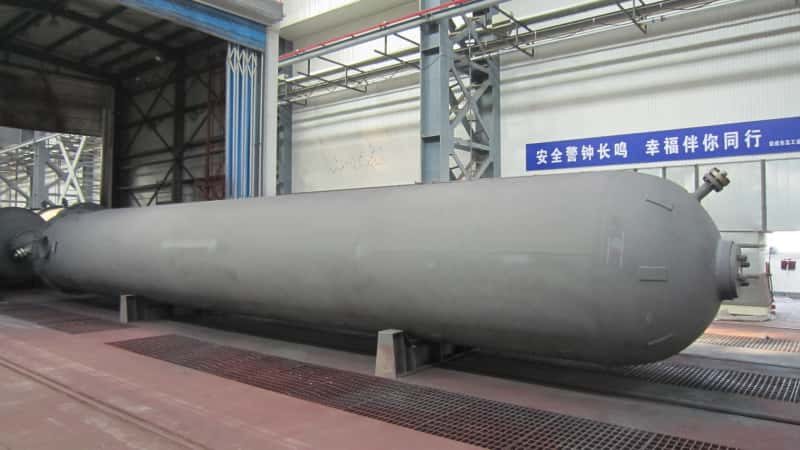

Design pressure and MAWP are related, but they are not the same thing.
In a typical pressure vessel project, design pressure is an engineering input used to establish the minimum pressure capability required from the vessel, while MAWP—Maximum Allowable Working Pressure—is the maximum pressure permitted for the completed vessel at a specified coincident temperature, as determined by the applicable design rules and the vessel’s pressure-retaining components.
In practical ASME pressure vessel procurement, the relationship is usually:
Operating Pressure → Design Pressure → Mechanical Design → Calculated MAWP
The final MAWP may be equal to or higher than the specified design pressure, but the two terms should not be used interchangeably.
This distinction matters because confusing them can affect:
- vessel wall thickness;
- material selection;
- nozzle and flange design;
- pressure-relief protection;
- hydrostatic testing;
- equipment nameplate data;
- RFQ specifications;
- future inspection and rerating.
The ASME Boiler and Pressure Vessel Code Section VIII Division 1 establishes requirements for the design, fabrication, inspection, testing, and certification of pressure vessels. For a completed vessel, MAWP is determined from the pressure capability of the applicable pressure-retaining parts at the designated coincident temperature.
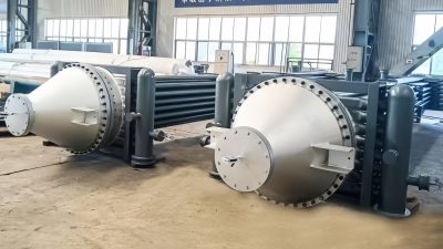
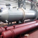
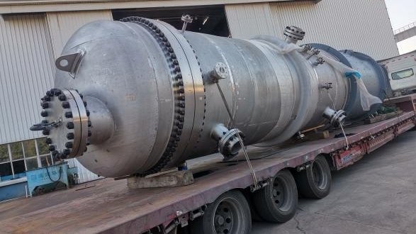
High-pressure industrial heat exchanger manufactured by Weihai Shidao Heavy Industry (WSHI). For pressure equipment operating under demanding process conditions, operating pressure, design pressure, design temperature, MAWP, materials, corrosion allowance, and pressure protection must be considered as one integrated design basis.
Executive Summary
The easiest way to understand the terminology is:
| Parameter | What It Means | Primarily Established By |
|---|---|---|
| Operating Pressure | Pressure normally experienced during operation | Process conditions |
| Maximum Operating Pressure | Highest pressure expected during normal or defined operation | Process engineering |
| Design Pressure | Pressure used as a design requirement for the vessel | Owner / EPC / process designer |
| MAWP | Maximum allowable pressure of the completed vessel at a specified temperature | Manufacturer / mechanical design |
| Relief Valve Set Pressure | Pressure at which the pressure-relief device is set to operate | System / relief design under applicable code |
| Test Pressure | Temporary pressure applied during hydrostatic or pneumatic testing | Applicable construction code |
The most important points are:
- Operating pressure is not MAWP.
- Design pressure is not automatically MAWP.
- MAWP is associated with a specific coincident temperature.
- The final vessel MAWP is controlled by the limiting pressure-retaining component.
- Corrosion allowance should not simply be counted as extra pressure capacity when MAWP is determined.
- Static liquid head can affect the allowable pressure at different elevations of a vessel.
- Pressure-relief set pressure should be established using the applicable overpressure-protection requirements—not guessed from operating pressure.
- Hydrostatic test pressure may temporarily exceed normal operating pressure and MAWP-related values under controlled code rules, but that does not authorize operation at the test pressure.
- EPC buyers should provide both operating conditions and design conditions in an RFQ rather than supplying one ambiguous pressure value.
Quick Answer: What Is the Difference Between Design Pressure and MAWP?
Design pressure is a specified engineering requirement. MAWP is a calculated allowable limit of the completed pressure vessel.
A process engineer or EPC contractor may determine that a vessel needs to be designed for, for example:
10 barg at 200°C
The pressure vessel manufacturer then performs the mechanical design using the specified:
- pressure;
- temperature;
- material;
- vessel diameter;
- corrosion allowance;
- joint efficiency;
- geometry;
- external loads;
- code requirements.
Once shell, heads, nozzles, closures, flanges, and other pressure-retaining components have been designed and nominal material thicknesses selected, the completed design may have a calculated MAWP that is somewhat higher than the original 10 barg design requirement.
For example:
| Parameter | Illustrative Value |
|---|---|
| Normal Operating Pressure | 8 barg |
| Maximum Operating Pressure | 8.8 barg |
| Specified Design Pressure | 10 barg |
| Shell Allowable Pressure | 11.8 barg |
| Head Allowable Pressure | 11.5 barg |
| Limiting Component Allowable Pressure | 11.2 barg |
| Vessel MAWP | 11.2 barg at specified temperature |
This example is only intended to explain the relationship; it is not an ASME design calculation.
The important point is that the vessel’s MAWP in this example is not 10 barg merely because the design pressure was 10 barg.
The actual design produces a pressure capability of 11.2 barg, with the limiting component determining the vessel MAWP.
What Is Operating Pressure?
Operating pressure is the pressure that the vessel normally experiences while the process is running.
For example, a separator might normally operate at:
7.5 barg
while the equipment is specified with a design pressure of:
10 barg
These values are deliberately different because real process systems can experience:
- normal pressure fluctuations;
- control-system variations;
- startup conditions;
- shutdown conditions;
- transient pressure increases;
- blocked-flow conditions;
- process disturbances.
The pressure vessel should not be designed around only a single stable operating value if credible operating conditions can produce higher pressure.
Operating Pressure Is a Process Parameter
Operating pressure normally originates from the process design.
It can depend on:
- feed pressure;
- compressor discharge pressure;
- reaction conditions;
- vapor pressure;
- pump characteristics;
- upstream pressure control;
- downstream resistance;
- process temperature;
- liquid level.
For an EPC project, the pressure-vessel manufacturer should therefore receive clear process data rather than being expected to determine the operating pressure independently.
What Is Design Pressure?
Design pressure is the pressure condition used as part of the mechanical design basis for the pressure vessel.
It is usually established by the owner, process licensor, EPC contractor, or engineering consultant before the manufacturer completes the vessel design.
The design pressure should account for the credible conditions that the equipment is required to withstand under the project design basis.
It is normally specified together with a design temperature.
For example:
Design Pressure: 2.5 MPaG
Design Temperature: 250°C
Pressure without temperature is incomplete information.
Material allowable stress can change with temperature, which means the same vessel geometry may not have the same allowable pressure at every temperature.
This is why a proper pressure vessel datasheet should define pressure and temperature as coincident design conditions.
For custom equipment procurement, see our detailed Pressure Vessel RFQ Documents Guide for EPC Buyers.
Does ASME Require Design Pressure to Be 10% Above Operating Pressure?
No universal ASME rule requires every pressure vessel design pressure to equal operating pressure plus 10%.
This is an important misconception.
You may encounter project specifications using rules such as:
- maximum operating pressure + 10%;
- operating pressure + a fixed pressure margin;
- whichever of a percentage or fixed increment is larger.
These can be legitimate owner, EPC, licensor, or company design practices, but they should not automatically be presented as a universal ASME requirement.
The correct design pressure depends on:
- process conditions;
- credible pressure excursions;
- relief philosophy;
- project specification;
- applicable design code;
- owner requirements.
This is particularly important when comparing quotations.
If one supplier assumes a 10% pressure margin while another receives a formally specified design pressure, their resulting vessel thicknesses and prices may not be directly comparable.
The buyer should therefore provide the required design pressure explicitly.
What Is MAWP?
MAWP stands for Maximum Allowable Working Pressure.
For an ASME pressure vessel, MAWP is fundamentally the maximum pressure permitted at the top of the completed vessel in its normal operating position at the specified coincident temperature.
A useful regulatory reproduction of the ASME Section VIII concept can be found in 46 CFR §54.10-5, which reproduces the relevant MAWP principles from Section VIII.
The MAWP of the overall vessel is governed by the lowest allowable pressure among its essential pressure-retaining parts after the applicable Code considerations are applied.
That means MAWP is not simply selected by the manufacturer as a convenient number.
It results from mechanical design.
Why Is MAWP Often Higher Than Design Pressure?
Pressure vessels are rarely manufactured using the mathematically exact minimum required plate thickness.
Suppose the Code calculation requires:
17.2 mm
of structural thickness.
The manufacturer may need to select:
18 mm, 20 mm, or another commercially available nominal thickness
depending on:
- available plate sizes;
- mill tolerances;
- corrosion allowance;
- forming requirements;
- fabrication tolerance;
- purchaser specification.
This can create additional pressure capability.
Similar effects can arise from:
- standard head thicknesses;
- nozzle neck thicknesses;
- flange ratings;
- available forging sizes;
- conservative component selection.
The completed vessel may therefore have a MAWP above the original specified design pressure.
However:
A higher MAWP should be treated as the result of the completed mechanical design—not as a reason to increase the process operating pressure without engineering review.
Can MAWP Equal Design Pressure?
Yes.
MAWP does not have to be substantially higher than design pressure.
Depending on the design, materials, nominal thicknesses, component ratings, purchaser requirements, and Code calculations, the final MAWP may be equal or very close to the specified design pressure.
Therefore, neither of these statements is universally correct:
“MAWP is always equal to design pressure.”
or:
“MAWP must always be significantly higher than design pressure.”
The actual relationship is determined by the specific equipment design.
Which Part of a Pressure Vessel Determines MAWP?
The vessel MAWP is controlled by its limiting pressure-retaining part.
Possible controlling components may include:
- cylindrical shell;
- formed head;
- nozzle neck;
- nozzle reinforcement;
- flange;
- closure;
- channel;
- tubesheet or other applicable pressure boundary;
- another Code-designed pressure-retaining component.
Consider a simplified vessel:
| Component | Calculated Allowable Pressure |
|---|---|
| Shell | 12.8 barg |
| Top Head | 12.2 barg |
| Bottom Head | 12.5 barg |
| Nozzle Assembly | 11.9 barg |
| Closure | 11.6 barg |
The vessel cannot simply be assigned a MAWP of 12.8 barg because the shell can withstand that pressure.
In this simplified example, the closure is the limiting component.
Therefore, subject to all applicable Code considerations, the overall vessel pressure capability cannot exceed the limiting component’s allowable pressure.
This is why MAWP is sometimes described informally as being controlled by the vessel’s weakest pressure-retaining component.
MAWP Depends on Temperature
A MAWP value without its associated temperature can be misleading.
Material allowable stress depends on temperature.
As temperature changes, the permissible stress for a material can change, which in turn can change the allowable pressure of the vessel.
ASME rules allow MAWP to be determined for designated coincident temperatures.
This means a vessel may conceptually have:
- one allowable pressure at 100°C;
- another allowable pressure at 300°C.
This does not mean the manufacturer can freely select whichever value is preferred.
The pressure-temperature combination must represent the defined design and operating basis.
For EPC buyers, this is why the RFQ should always provide:
Design Pressure + Design Temperature
rather than pressure alone.
Design Temperature vs Operating Temperature
The same distinction exists between operating and design temperature.
Operating Temperature
The temperature normally experienced during operation.
Design Temperature
The temperature used as part of the mechanical design condition.
Design temperature can affect:
- allowable material stress;
- material grade;
- impact-testing requirements;
- creep considerations;
- flange rating;
- gasket selection;
- PWHT requirements;
- vessel wall thickness.
Therefore, a pressure vessel specified simply as:
20 barg
is incomplete.
A much better specification is:
Design Pressure: 20 barg
Design Temperature: 350°C
This gives the mechanical designer a pressure-temperature pair that can actually be evaluated.
How Does Static Head Affect MAWP?
Static liquid head is particularly important in:
- tall vertical reactors;
- process columns;
- absorbers;
- separators;
- liquid-filled vessels.
MAWP is normally referenced to the top of the vessel in its normal operating position.
However, the lower parts of a liquid-filled vessel experience additional hydrostatic pressure.
For a tall vessel:
Pressure at Bottom = Pressure at Top + Static Liquid Head
This means a bottom shell course may experience substantially more internal pressure than the top of the vessel.
The mechanical design must account for that difference.
This becomes increasingly important for large process towers and columns where:
- vessel height is large;
- process liquid density is high;
- liquid inventory is significant.
Ignoring static head can result in an incorrect understanding of the required wall thickness or local pressure condition.
How Does Corrosion Allowance Affect MAWP?
Corrosion allowance is another area where MAWP is frequently misunderstood.
Suppose the required structural thickness is:
20 mm
and the specified corrosion allowance is:
3 mm
The vessel might therefore require a nominal design thickness exceeding the structural requirement to account for anticipated future metal loss.
But that 3 mm corrosion allowance should not simply be treated as additional pressure capacity available for normal operation.
The ASME-derived MAWP provisions reproduced in 46 CFR §54.10-5 specifically address the calculation of allowable pressure using thickness exclusive of specified corrosion allowance.
This principle matters because corrosion allowance exists to accommodate expected material loss during service.
It is not a free operating-pressure margin.
For further material considerations, see our Pressure Vessel Material Selection Guide.
Does Corrosion Reduce MAWP Over Time?
Potentially, yes—but the situation must be handled within an appropriate in-service integrity framework.
As a vessel loses wall thickness through corrosion, the remaining pressure-retaining capability can decline.
This does not mean operators should simply recalculate a lower pressure informally and continue operating.
In-service pressure equipment may require:
- inspection;
- thickness measurement;
- engineering evaluation;
- rerating;
- repair;
- Fitness-for-Service assessment;
- formal documentation.
For more detail, see:
How Often Should Pressure Vessels Be Inspected?
and:
How Long Do Pressure Vessels Last?
The key principle is:
Nameplate MAWP should not be treated as proof that an aging or damaged vessel remains suitable for that pressure indefinitely.
Actual equipment condition still matters.
Design Pressure vs MAWP vs Relief Valve Set Pressure
These three values are closely related but serve different purposes.
Design Pressure
Used as a mechanical design requirement.
MAWP
Maximum allowable pressure of the completed vessel at the specified temperature.
Relief Valve Set Pressure
The pressure at which a pressure-relieving device is set to operate.
Pressure-relief protection should be designed according to the applicable Code and process-system requirements.
The current ASME BPVC Section XIII addresses overpressure protection for pressurized equipment including pressure vessels and covers relief devices, testing, marking, installation, capacity, and system design.
A common mistake is to assume:
Relief Valve Set Pressure = Design Pressure
This should not be used as a universal rule.
The required relief set pressure depends on:
- vessel MAWP;
- applicable Code;
- process relief scenarios;
- system configuration;
- upstream and downstream conditions;
- multiple relief-device arrangements where applicable.
For Section VIII pressure equipment, MAWP is a fundamental reference for overpressure protection.
The relief system should therefore be engineered after the pressure relationships are understood, rather than selecting a set pressure simply because it matches a number on the process datasheet.
Can Pressure Ever Exceed MAWP?
This question requires an important distinction between normal operation and a Code-defined overpressure event.
MAWP should not be treated as the normal target operating pressure.
However, applicable overpressure-protection rules can permit limited pressure accumulation above MAWP during specified relief scenarios.
That does not mean the equipment can continuously operate above MAWP.
The allowable amount and conditions depend on the applicable Code provisions and relief scenario.
Therefore:
MAWP is not the same thing as allowable temporary accumulation during an overpressure event.
For actual projects, the vessel design and the pressure-relief system must be reviewed together.
Design Pressure vs MAWP vs Hydrostatic Test Pressure
Hydrostatic test pressure creates another common source of confusion.
A pressure vessel may be hydrotested at a pressure significantly above its normal operating pressure.
This does not mean that the hydrotest pressure becomes the vessel’s allowable operating pressure.
Hydrostatic testing is a controlled construction or integrity test carried out under specific Code rules.
Its purpose is different from normal operation.
The relationship can be summarized as:
| Pressure | Purpose |
|---|---|
| Operating Pressure | Normal process operation |
| Design Pressure | Mechanical design requirement |
| MAWP | Allowable pressure limit for completed vessel at specified temperature |
| Hydrotest Pressure | Temporary controlled test condition |
ASME Section VIII establishes the applicable test requirements, including the relationship between pressure, MAWP, material allowable stresses, and test temperature.
For a detailed explanation, see:
Hydrostatic vs Pneumatic Pressure Vessel Testing
The important procurement principle is:
Do not use hydrotest pressure as the equipment’s working-pressure rating.
Why Test Pressure Can Be Higher Without Meaning the Vessel Can Operate There
Hydrostatic testing normally uses water or another suitable liquid.
Liquids are comparatively incompressible, which means the stored-energy characteristics differ substantially from pneumatic testing with compressed gas.
The test is also:
- temporary;
- controlled;
- performed under defined conditions;
- carried out at a known test temperature;
- monitored during fabrication or inspection.
Normal service is completely different.
A vessel may operate continuously for thousands of hours while exposed to:
- temperature;
- corrosion;
- cyclic loads;
- process chemistry;
- external mechanical loads.
The ability to survive a factory hydrostatic test therefore does not redefine the vessel’s operating envelope.
Why Shell-and-Tube Heat Exchangers Need More Than One Pressure Value
Shell-and-tube heat exchangers demonstrate why pressure terminology must be handled carefully.
A shell-and-tube heat exchanger contains two separate process sides:
Shell Side
and:
Tube Side
Each side can have its own:
- operating pressure;
- design pressure;
- design temperature;
- MAWP;
- corrosion allowance;
- pressure test requirement.
For example:
| Parameter | Shell Side | Tube Side |
|---|---|---|
| Operating Pressure | 5 barg | 70 barg |
| Design Pressure | 8 barg | 85 barg |
| Design Temperature | 180°C | 220°C |
| Material | Carbon Steel | Alloy Steel |
The manufacturer cannot simply be told:
“Heat exchanger pressure: 85 barg.”
That would leave critical design information unresolved.
Engineers may also need to consider:
- differential pressure;
- tube failure scenarios;
- startup/shutdown conditions;
- blocked-in conditions;
- thermal expansion;
- external pressure or vacuum.
This is why high-pressure heat exchangers require both thermal and mechanical design information before reliable fabrication pricing can be prepared.
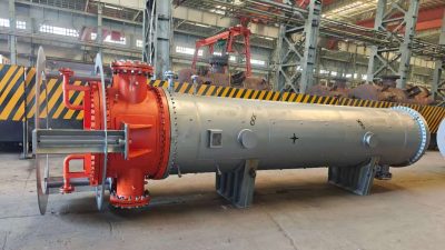
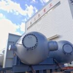
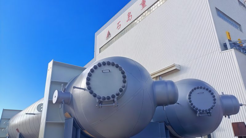
Industrial heat exchanger manufactured by WSHI. Shell-side and tube-side design conditions should be specified separately because each pressure boundary can have a different operating pressure, design pressure, temperature, material, and MAWP.
Why High-Pressure Reactors Make MAWP Especially Important
The distinction becomes even more important for large thick-wall reactors.
WSHI’s industrial reactor manufacturing scope includes project-specific equipment for pressure service up to approximately 35 MPa, depending on the application and project design.
High-pressure refinery equipment may involve:
- thick forged sections;
- Cr-Mo steels;
- corrosion-resistant weld overlay;
- large nozzles;
- heavy closures;
- high design temperatures;
- hydrogen service.
One example is the Xinyue Fuel Chemical Hydrocracking Reactor Project.
Published project data include:
| Parameter | Project Data |
|---|---|
| Equipment | Hydrocracking Reactor |
| Diameter | φ4000 mm |
| Wall Configuration | 212 + 6.5 mm |
| Length | 22,049 mm |
| Weight | 626.6 tons |
| Base Material | 12Cr2Mo1V forged |
| Overlay | E309L + E347 |
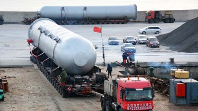
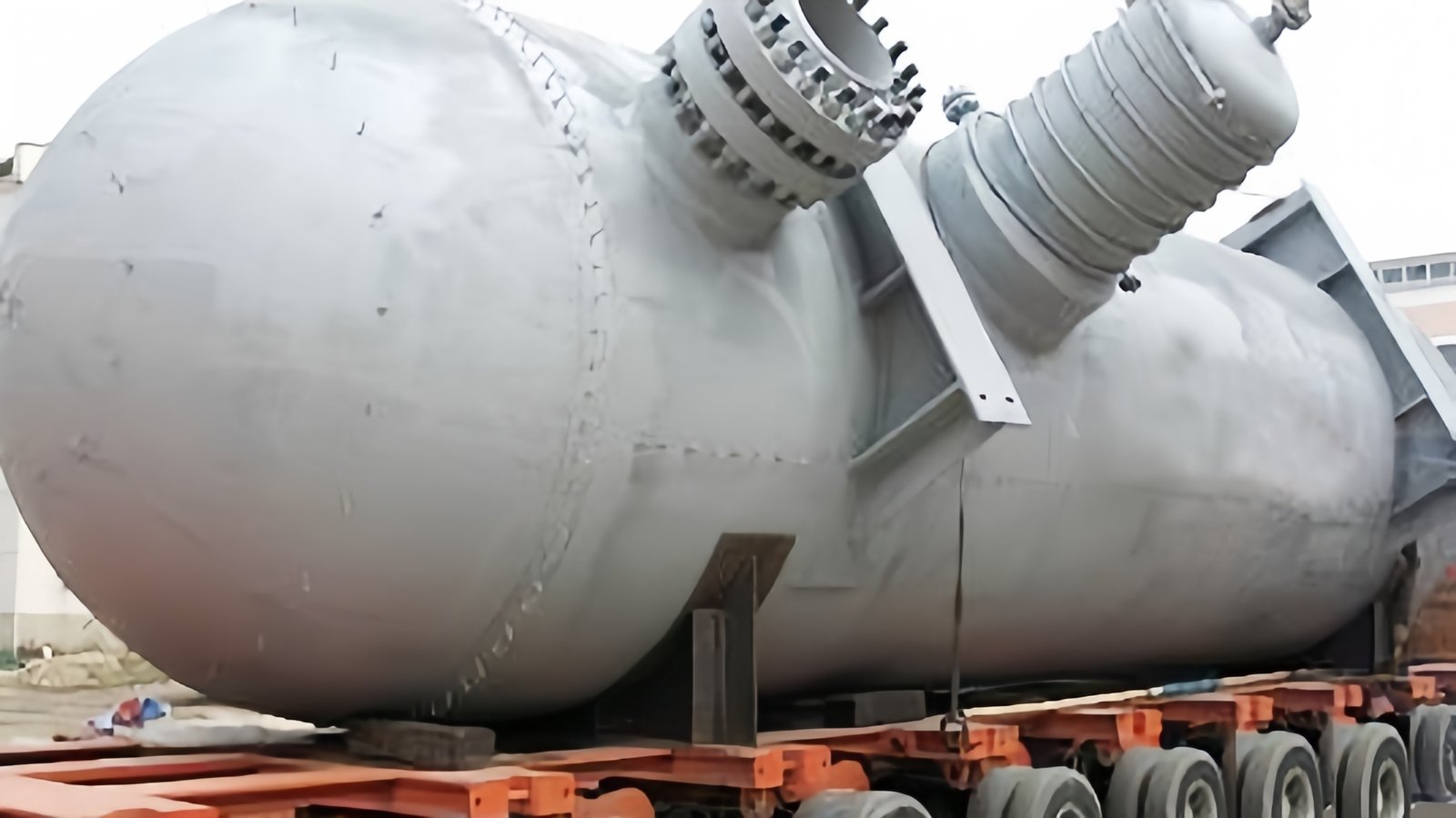
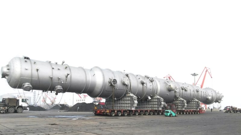
Large hydrocracking reactor manufactured by WSHI. For thick-wall, high-pressure equipment, MAWP results from the complete mechanical design rather than from a single process pressure value.
For equipment of this scale, a small change in design pressure can affect:
- required wall thickness;
- forging dimensions;
- material weight;
- welding volume;
- PWHT;
- manufacturing cycle;
- lifting requirements;
- transportation;
- total equipment cost.
That is why accurate pressure definitions should be established before quotation and detailed design.
What Happens If Design Pressure Is Increased Late in a Project?
A late design-pressure increase can have major consequences.
Suppose the original RFQ states:
Design Pressure: 6.0 MPa
After the vessel has already entered detailed design, the EPC contractor changes it to:
7.0 MPa
That change may require reassessment of:
- shell thickness;
- head thickness;
- nozzle reinforcement;
- flange rating;
- gasket;
- bolts;
- material quantity;
- welding volume;
- heat treatment;
- NDE;
- supports;
- weight;
- lifting;
- transportation.
If material has already been ordered, the change can become expensive.
For large thick-wall equipment, additional plate or forging thickness may also involve long procurement lead times.
This is why pressure data should be clarified during the RFQ and technical-bid stage rather than after purchase order placement.
What Happens If the Operating Pressure Changes After Commissioning?
Operating pressure should not be increased simply because the nameplate MAWP is higher than the original operating pressure.
An increase can affect:
- pressure-relief capacity;
- piping;
- valves;
- flanges;
- connected equipment;
- process control;
- vessel fatigue;
- equipment supports;
- downstream systems.
The complete system should be reviewed through an appropriate Management of Change process.
For example:
Operating Pressure = 8 barg
Design Pressure = 10 barg
MAWP = 11.2 barg
does not automatically mean:
“We can increase plant operating pressure to 11 barg.”
The original process design and safety systems may never have been designed for that operating condition.
MAWP defines equipment pressure capability under its applicable conditions; it is not a production target.
What About Vacuum or External Pressure?
Pressure vessels are not always loaded from the inside.
Some equipment can experience:
- full vacuum;
- partial vacuum;
- steam-out conditions;
- condensing vapor;
- blocked-in cooling;
- jacket pressure acting externally on the inner vessel.
External pressure can cause buckling, which is a fundamentally different design problem from internal-pressure membrane stress.
Therefore, an RFQ that states only:
Design Pressure: 10 barg
may still be incomplete if the vessel can experience vacuum.
The buyer should specify conditions such as:
Internal Design Pressure: 10 barg
External Design Pressure: Full Vacuum
where applicable.
This is particularly important for:
- vacuum towers;
- condensers;
- jacketed reactors;
- process columns;
- vessels exposed to steam cleaning followed by condensation.
Internal-pressure MAWP should not be assumed to demonstrate adequate external-pressure resistance.
Design Pressure vs MAWP in ASME Division 1 and Division 2
The fundamental distinction between required design conditions and allowable vessel pressure remains relevant whether the equipment is engineered under:
or:
However, the detailed design methods, allowable stresses, examination requirements, fatigue evaluation, and other provisions differ between the Divisions.
Therefore, buyers should not decide the Code Division simply from pressure alone.
The applicable Division should be established according to:
- project specification;
- jurisdiction;
- vessel design conditions;
- cyclic service;
- economics;
- required analysis;
- owner requirements.
This topic also connects directly to ASME U vs U2 Stamp, which should be evaluated separately from the simpler question of design pressure versus MAWP.
Who Sets Design Pressure and Who Determines MAWP?
A useful project responsibility model is:
Owner / Process Licensor / EPC
Typically establishes:
- operating pressure;
- maximum operating pressure;
- design pressure;
- operating temperature;
- design temperature;
- process medium;
- upset cases;
- relief scenarios;
- corrosion basis.
Pressure Vessel Manufacturer
Typically performs or completes the mechanical design and determines:
- required pressure-boundary thickness;
- component design;
- material thickness;
- nozzle reinforcement;
- applicable joint efficiency;
- mechanical-load assessment;
- calculated MAWP;
- test requirements;
- manufacturing documentation.
The exact division of responsibility depends on the contract.
Some EPC projects provide complete mechanical calculations.
Others provide process datasheets and specifications and require the pressure vessel manufacturer to complete the mechanical design.
What matters is that the responsibility is clearly defined.
What Pressure Should an EPC Buyer Put in the RFQ?
Ideally, do not provide only one pressure.
For a custom pressure vessel RFQ, provide at least:
Process Conditions
- Normal operating pressure
- Maximum operating pressure
- Normal operating temperature
- Maximum / minimum operating temperature
Mechanical Design Conditions
- Design pressure
- Design temperature
- External pressure / vacuum requirement
- Corrosion allowance
Process Information
- Medium
- Composition
- Density
- Liquid level
- Specific gravity where relevant
- Corrosion data
Code Information
- ASME VIII-1 / VIII-2 / other applicable code
- Required Code stamp
- Local regulatory requirements
- Owner / EPC specifications
Pressure Protection
- Relief philosophy where available
- Relief valve data
- Credible upset conditions
Testing
- Hydrostatic or pneumatic test requirements
- Special cleanliness or drying requirements
For a complete procurement list, see:
What Should Be Included in a Custom Pressure Vessel RFQ Package?
Seven Common Design Pressure and MAWP Mistakes
1. Using Operating Pressure as Design Pressure Without Review
Normal operating conditions may not capture credible maximum conditions.
2. Giving Pressure Without Temperature
A pressure rating without the coincident temperature is incomplete for mechanical design.
3. Assuming MAWP Must Equal Design Pressure
The final MAWP depends on the completed design.
4. Treating Corrosion Allowance as Extra Pressure Capacity
Corrosion allowance exists to accommodate anticipated material loss.
5. Assuming Relief Set Pressure Automatically Equals Design Pressure
Relief protection must be established according to MAWP, relief scenarios, and applicable Code rules.
6. Treating Hydrotest Pressure as Working Pressure
A temporary test condition does not redefine the vessel’s normal operating limit.
7. Ignoring Static Head or Vacuum
Large vertical vessels and vacuum-service equipment require additional pressure-condition consideration.
Pressure Relationship Checklist for EPC Buyers
Before releasing a pressure vessel RFQ or approving the manufacturer’s design, confirm:
- Normal operating pressure is defined
- Maximum operating pressure is defined
- Design pressure is defined
- Normal operating temperature is defined
- Design temperature is defined
- Maximum and minimum temperature conditions are evaluated
- Static liquid head is considered
- Vacuum / external-pressure conditions are defined
- Process upset conditions are identified
- Corrosion allowance is specified
- Applicable Code is defined
- Required Code Division is defined
- Shell-side and tube-side conditions are separately defined for heat exchangers
- Jacket pressure is defined for jacketed vessels
- Pressure-relief philosophy is coordinated with vessel MAWP
- Hydrostatic / pneumatic test requirements are defined
- Final calculated MAWP is reviewed
- Nameplate information matches approved documentation
- Late process-pressure changes are subject to engineering review
What Should Buyers Check When Selecting a Pressure Vessel Manufacturer?
Pressure design becomes increasingly important as equipment moves toward:
- higher pressure;
- higher temperature;
- larger diameter;
- thicker wall;
- greater weight;
- severe corrosion;
- hydrogen service;
- cyclic operation.
Supplier evaluation should therefore consider more than quoted vessel capacity.
| Capability | Why It Matters |
|---|---|
| ASME qualifications | Supports Code construction requirements |
| Mechanical engineering capability | Converts process conditions into compliant pressure-boundary design |
| Material experience | Important for high-temperature, hydrogen and corrosive service |
| Thick-wall fabrication | Increasing pressure can dramatically increase required thickness |
| Forging capability | Critical for heavy-wall nozzles, shells and closures |
| Welding qualifications | Directly affect pressure-boundary integrity |
| PWHT capability | Important for applicable thick-wall and alloy equipment |
| NDE capability | Supports verification of pressure-retaining welds |
| Quality documentation | Provides traceability for MAWP and Code compliance |
| Heavy lifting capability | Becomes important as pressure-driven wall thickness increases equipment weight |
WSHI Pressure Vessel Manufacturing Capability
Weihai Shidao Heavy Industry (WSHI) specializes in large, tailor-made industrial pressure vessels and heavy process equipment.
Its manufacturing scope includes:
For reactor manufacturing, WSHI publishes capabilities including:
| Parameter | Published Capability |
|---|---|
| Diameter | Up to Ø10,000 mm |
| Length | Up to 60,000 mm |
| Wall Thickness | Up to 300 mm |
| Pressure | Up to approximately 35 MPa |
| Equipment Weight | Up to 960 tons |
| Temperature | Up to approximately 575°C |
The company also publishes ASME U/U2 certification and experience with carbon steel, low-alloy steel, stainless steel, Cr-Mo steels, clad construction, and other special-material pressure equipment.
For high-pressure equipment, the objective is not simply to produce a thicker vessel.
The complete pressure boundary must be engineered around:
pressure + temperature + material + geometry + corrosion + welding + NDE + heat treatment + external loads + process conditions
Planning a Custom Pressure Vessel Project?
For a reliable technical and commercial evaluation, provide as much of the following information as possible:
equipment type + operating pressure + design pressure + operating temperature + design temperature + process medium + material + corrosion allowance + dimensions + design code + vacuum requirement + NDE requirements + quantity + drawings/datasheet
Contact the WSHI engineering team to discuss your pressure vessel, reactor, heat exchanger, tower, or industrial storage equipment requirements.
Frequently Asked Questions
Is design pressure the same as MAWP?
No.
Design pressure is normally an engineering input used to establish the required mechanical design condition.
MAWP is the maximum allowable working pressure determined for the completed pressure vessel at a specified coincident temperature according to the applicable design rules.
The final MAWP may equal or exceed the specified design pressure depending on the completed design.
Is MAWP higher than design pressure?
It often can be, because commercially available plate thicknesses, forgings, heads, flanges, and other components may provide more pressure capability than the mathematical minimum required for the specified design pressure.
However, MAWP is not required to be substantially higher in every vessel.
It may be equal or close to the design pressure.
Is MAWP the same as operating pressure?
No.
Operating pressure is the pressure the equipment normally experiences in service.
MAWP represents an allowable pressure limit for the completed vessel at a specified temperature.
Normal operation should provide appropriate margin rather than using MAWP as the routine process target.
Who determines the MAWP of a pressure vessel?
For a new ASME pressure vessel, the manufacturer establishes the vessel’s MAWP through mechanical design using the applicable Code requirements, materials, geometry, nominal thicknesses, corrosion allowance treatment, pressure-retaining components, and design temperature.
What determines pressure vessel MAWP?
MAWP can depend on:
- material allowable stress;
- temperature;
- shell thickness;
- head geometry;
- vessel diameter;
- weld joint efficiency;
- nozzle and closure design;
- applicable loadings;
- corrosion allowance;
- static head;
- other Code requirements.
The overall vessel MAWP is limited by the pressure capability of the controlling essential component.
Does MAWP change with temperature?
It can.
MAWP is associated with a designated coincident temperature because material allowable stress varies with temperature.
A vessel should therefore not be described only by a pressure without considering the associated temperature.
Is design pressure always 10% above operating pressure?
No.
A 10% margin is sometimes used in project or company design practices, but it is not a universal ASME rule for every pressure vessel.
The owner, EPC contractor, or process engineer should establish design pressure based on the actual process conditions, credible excursions, project standards, and applicable Code requirements.
Can operating pressure exceed design pressure?
Normal operation should remain within the established process and equipment operating envelope.
Operating above the specified design basis should not be done simply because the calculated MAWP happens to be higher.
A change in operating pressure requires review of the vessel, relief system, piping, valves, connected equipment, process control, and other relevant systems.
Can a pressure vessel operate at MAWP continuously?
MAWP should not automatically be treated as a recommended continuous operating target.
The normal operating pressure is established by the process design and normally includes appropriate separation from pressure limits and relief-system activation.
Any change toward higher operating pressure should be subject to engineering review.
Is relief valve set pressure the same as MAWP?
Not necessarily in every system configuration, but MAWP is a fundamental parameter used when establishing pressure-relief protection for an ASME pressure vessel.
The applicable ASME overpressure-protection provisions, process relief scenarios, number of devices, and system design determine the correct setting.
Can the pressure exceed MAWP when a relief valve operates?
Applicable pressure-vessel rules can permit limited temporary accumulation above MAWP during certain Code-defined overpressure scenarios.
This should not be confused with normal operation above MAWP.
The allowable accumulation depends on the applicable Code and relief scenario.
Is hydrostatic test pressure the same as MAWP?
No.
Hydrostatic test pressure is a temporary controlled test condition established according to applicable Code requirements.
It does not become the vessel’s allowable normal operating pressure.
Does corrosion allowance increase MAWP?
Specified corrosion allowance should not simply be treated as additional usable pressure thickness.
It exists to accommodate anticipated material loss during service, and applicable ASME MAWP principles account for corrosion allowance accordingly.
Why is MAWP shown on a pressure vessel nameplate?
MAWP communicates an important allowable pressure rating for the completed vessel at its designated temperature and forms part of the equipment’s Code documentation and pressure-protection basis.
It helps owners, inspectors, engineers, and operators understand the rated pressure limit of the equipment.
What should I specify when requesting a pressure vessel quotation?
At minimum, provide:
- operating pressure;
- design pressure;
- operating temperature;
- design temperature;
- process medium;
- material requirement;
- corrosion allowance;
- vessel dimensions or capacity;
- applicable design code;
- external-pressure or vacuum requirements;
- inspection and NDE requirements.
For EPC procurement, a complete process datasheet and mechanical specification are strongly recommended.
Conclusion
The difference between design pressure and MAWP is fundamental to pressure vessel engineering.
Design pressure is primarily a required design input.
MAWP is primarily a result of the completed mechanical design.
The relationship can be summarized as:
Process Conditions → Operating Pressure → Design Pressure & Temperature → Mechanical Design → Component Pressure Capability → MAWP → Overpressure Protection
But these values should not be treated as interchangeable.
A reliable pressure vessel specification must distinguish among:
- operating pressure;
- maximum operating pressure;
- design pressure;
- design temperature;
- MAWP;
- relief valve set pressure;
- hydrostatic or pneumatic test pressure.
The distinction becomes particularly important for large reactors, high-pressure heat exchangers, separators, process columns, and industrial storage vessels where even modest changes in pressure can materially affect wall thickness, material weight, welding volume, heat treatment, manufacturing cost, and project delivery.
For EPC contractors and industrial buyers, the practical lesson is straightforward:
Do not send a pressure vessel manufacturer only one pressure number.
Provide the complete operating and design envelope.
The manufacturer can then engineer the pressure boundary, determine the final MAWP, coordinate testing and documentation, and manufacture equipment that matches the actual process requirement rather than an assumption.
Standards and Technical References
- ASME BPVC Section VIII Division 1 — Rules for Construction of Pressure Vessels
- ASME 2025 Boiler and Pressure Vessel Code
- ASME BPVC Section XIII — Rules for Overpressure Protection
- 46 CFR §54.10-5 — Maximum Allowable Working Pressure
- ABSA — Design Pressure vs MAWP for Pressure Vessels
- National Board — Pressure Relief Technical Guidance