Flare gas recovery systems collect normally flared gas, remove liquids, raise pressure, and route recovered gas back to a useful destination such as the fuel gas header, gas treating unit, or process system. For refineries, petrochemical plants, gas plants, LNG facilities, and offshore projects, the pressure equipment must be selected carefully because it connects directly to the flare system, which remains a critical safety disposal route for emergency relief.
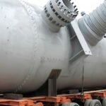
A typical flare gas recovery package may include flare header tie-ins, isolation and bypass valves, knockout drums, liquid seal drums, suction scrubbers, liquid ring compressors, screw compressors, ejectors, discharge separators, service-liquid separators, coolers, condensate receivers, recovered gas receivers, relief devices, pressure control valves, check valves, ESD valves, instrumentation, and control systems. The exact equipment depends on flare gas composition, normal flare flow, liquid loading, sour service, suction pressure, discharge pressure, and the destination of the recovered gas.
EPA flare guidance describes typical flare components such as gas transport piping, knockout drums, liquid seals, flare stacks, burner tips, pilots, ignition systems, and controls. Zeeco describes flare gas recovery as a process where gas is redirected from the flare header, compressed or handled by ejector systems, separated, cooled, and returned for reuse. API Standard 521 is commonly referenced for pressure-relieving and depressurizing systems. These references all point to the same procurement rule: a flare gas recovery system must recover routine flare gas while preserving the flare as the final safe relief path.
A flare gas recovery system should recover normal flare header gas without preventing emergency relief gas from reaching the flare.True
The flare remains a safety disposal system, so recovery equipment must include pressure control, bypass, shutdown, and backflow prevention features that allow emergency relief gas to reach the flare.
A flare gas recovery compressor can be connected to a flare header without reviewing flare hydraulics or pressure protection.False
The recovery package can affect flare header pressure, air ingress risk, liquid carryover, and emergency relief routing, so flare hydraulics, relief cases, and safeguards must be reviewed before tie-in.
What Pressure Equipment Is Used in Flare Gas Recovery Systems?
The core equipment starts at the flare header and continues through liquid removal, compression or ejector recovery, cooling, separation, recovered gas conditioning, and safe bypass back to the flare. The package must handle variable low-pressure gas, condensable hydrocarbons, water, sour components, oxygen ingress risk, changing flow rates, and emergency isolation requirements.
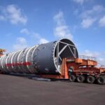
For fabricated equipment planning, buyers can review custom pressure vessels, pressure vessels for oil and gas, petrochemical pressure vessels, and industrial heat exchangers.
| System section | Core pressure equipment | Main function | Buyer design check |
|---|---|---|---|
| Flare header interface | Tie-in spool, isolation valves, pressure transmitter, bypass path | Connect recovery unit without compromising flare relief | Confirm emergency relief gas still reaches the flare safely |
| Liquid removal before recovery | Flare knockout drum, suction scrubber, demister, drains | Remove slugs, condensate, and mist | Size for credible liquid loads and low pressure drop |
| Air ingress and flashback protection | Liquid seal drum, deep seal, backpressure control vessel | Maintain positive pressure and reduce flashback risk | Check seal depth, seal liquid management, and winterization |
| Compression or recovery | Liquid ring compressor, screw compressor, reciprocating compressor, ejector | Raise flare gas pressure for reuse | Match technology to gas composition, liquid load, and pressure ratio |
| Discharge separation | Compressor discharge separator, service-liquid separator, oil separator | Separate gas from working liquid, oil, and condensate | Prevent liquid carryover to fuel gas or process return |
| Heat removal | Service-liquid cooler, interstage cooler, aftercooler, condenser | Remove compression heat and condense liquids | Check fouling, hydrate risk, corrosion, and winterization |
| Recovered gas conditioning | Receiver, fuel gas KO drum, sweetening or guard vessel if required | Deliver usable recovered gas | Confirm fuel gas quality, H2S limits, and liquid-free discharge |
| Pressure protection | PSV, rupture disc, thermal relief, blowdown and bypass valves | Protect equipment and preserve flare availability | Include blocked-in, fire, compressor, and exchanger failure cases |
Flare Header Tie-In and Bypass Equipment
The recovery suction connection is usually taken from the flare header before gas reaches the flare stack. This connection must not block or restrict emergency relief flow. Isolation valves, control valves, non-return devices, pressure transmitters, emergency bypass, and shutdown logic should be designed so that the flare remains available if the recovery unit trips, overloads, or is isolated for maintenance.
Engineers should review flare header hydraulics, relief cases, purge gas, oxygen ingress risk, compressor suction pressure, and possible vacuum conditions. The system should normally recover routine flare loads, not emergency relief loads. Excess gas must still pass safely to the flare.
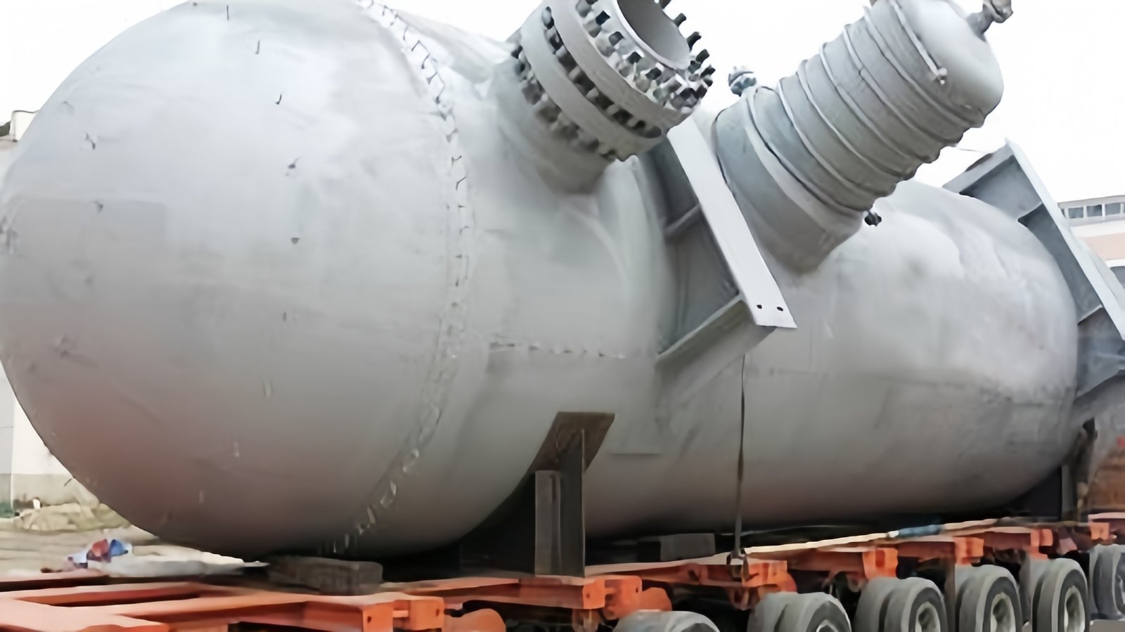
Knockout Drums and Suction Scrubbers
Flare gas can contain liquid hydrocarbons, water, aerosols, amine carryover, slugs, and solids. A flare knockout drum removes bulk liquids before gas continues to the flare or recovery package. A dedicated suction scrubber near the compressor provides final liquid protection before compression. This is especially important for liquid ring, screw, and reciprocating compressor packages.
Knockout drums and scrubbers should include suitable inlet devices, demisters or vane packs, liquid residence volume, level instruments, high-high level shutdown, drains to closed systems, pressure protection, and sour service materials where required. For related separator vessels, buyers can review custom pressure vessels and oil and gas separator equipment.
Liquid Seal Drums and Backpressure Control
Liquid seal drums help maintain positive pressure in the flare header and reduce the risk of air ingress or flashback. In flare gas recovery service, this becomes more important because compressors can pull gas from the flare header and may create low-pressure or vacuum conditions if not controlled properly.
The liquid seal drum should be designed around seal depth, flow capacity, seal liquid management, freezing risk, fouling, instrumentation, drain routing, and pressure vessel requirements. A poorly designed seal can create unstable header pressure, seal liquid carryover, freezing problems, or insufficient protection during operating transitions.
Compressors and Ejectors
The compressor or ejector is the pressure-boosting equipment in the recovery package. Flare headers usually operate at low pressure, while recovered gas must be delivered to a higher-pressure fuel gas header, treatment unit, or process destination.
Liquid ring compressors are common because flare gas can be wet, variable, and low-pressure. Dry screw or flooded screw compressors may be selected for higher pressure or specific project requirements. Reciprocating compressors may be used where high discharge pressure is needed, but they are more sensitive to liquid carryover. Ejectors may be attractive where high-pressure motive gas or liquid is available and simpler rotating equipment is desired.
| Recovery device | Typical fit | Pressure equipment around it | Main design concern |
|---|---|---|---|
| Liquid ring compressor | Wet, dirty, variable flare gas | Suction scrubber, service-liquid separator, cooler, discharge separator | Service-liquid management and separator sizing |
| Dry screw compressor | Higher discharge pressure where service liquid is not desired | Suction scrubber, interstage cooler, aftercooler, discharge KO drum | Liquid carryover, temperature, vibration, and noise |
| Flooded screw compressor | Higher pressure with oil-injected compression | Oil separator, oil cooler, oil pump, suction scrubber, aftercooler | Oil carryover and downstream contamination |
| Reciprocating compressor | High discharge pressure or staged compression | Suction scrubber, pulsation bottles, interstage KO drums, coolers | Pulsation, liquid sensitivity, and maintenance |
| Ejector | Simple recovery where motive fluid is available | Motive fluid piping, downstream separator if liquid or steam is used | Motive utility consumption and operating range |
Discharge Separators, Coolers, and Receivers
After compression, recovered gas may contain condensed hydrocarbons, water, oil, service liquid, or entrained droplets. Discharge separators, service-liquid separators, aftercooler knockout drums, condensate receivers, and recovered gas receivers remove liquids and stabilize the gas before it enters the fuel gas header or process system.
 equipment for flare gas recovery systems](https://pressure-tank.com/wp-content/uploads/2026/04/heat-exchanger.png)
Coolers may include service-liquid coolers, interstage coolers, aftercoolers, or condensers. Heat removal affects hydrocarbon condensation, corrosion risk, hydrate risk, downstream gas quality, and compressor performance. Where a shell-and-tube arrangement is required, buyers may review shell and tube heat exchanger options for custom service.
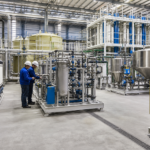
Recovered Gas Conditioning
Recovered gas may require additional conditioning before reuse. Depending on composition, this may include a fuel gas knockout drum, H2S removal, amine treating, adsorber vessels, guard beds, liquid filtration, or hydrocarbon dew point control. If recovered gas is sent to a fuel gas header, buyers should confirm pressure, heating value, H2S limit, liquid content, oxygen risk, and control philosophy.
Pressure Protection and Safety Controls
The recovery package must not compromise flare safety. Pressure protection may include PSVs, rupture discs, thermal relief valves, blowdown valves, bypass valves, recycle lines, pressure control valves, check valves, ESD valves, high liquid level trips, high discharge pressure trips, low suction pressure trips, oxygen monitoring where required, and compressor shutdown logic.
API Standard 521 is a key reference for pressure-relieving and depressurizing systems. Final requirements should be confirmed through project relief calculations, flare studies, HAZOP, LOPA or SIL review where applicable, and owner engineering standards.
Materials and Corrosion Control
Flare gas may contain H2S, CO2, water, chlorides, amines, caustic, acids, oxygen, hydrocarbons, and particulates. Materials should be selected based on sour service, corrosion allowance, minimum design metal temperature, maximum operating temperature, liquid chemistry, and project specifications.
Pressure vessels and separators should define design pressure, design temperature, MAWP, corrosion allowance, internals, level instrumentation, relief devices, drains, vents, manways, and access for demister removal or cleaning.
Manufacturing and Quality Control
A qualified manufacturer should review process datasheets, mechanical drawings, material specifications, internals requirements, welding requirements, NDT scope, pressure testing, coating, packing, and delivery conditions before fabrication starts. For flare gas recovery systems, documentation is especially important because the package is tied to pressure relief, environmental performance, and plant safety.

What Buyers Should Prepare Before Requesting a Quotation
Before requesting a quotation for flare gas recovery pressure equipment, buyers should prepare:
- Normal flare gas flow and peak recoverable flow
- Flare gas composition, including H2S, CO2, water, oxygen, hydrocarbons, and contaminants
- Flare header pressure and allowable pressure range
- Recovered gas destination and required discharge pressure
- Liquid loading, slug cases, and condensate composition
- Preferred compressor or ejector technology if already studied
- Flare hydraulic and relief system constraints
- Liquid seal and backpressure control requirements
- Sour service and material requirements
- PSV, ESD, blowdown, bypass, and recycle requirements
- Instrumentation, analyzer, and DCS/PLC integration requirements
- Inspection, NDT, pressure testing, coating, and documentation requirements
- Skid layout, maintenance access, transport, and site installation limits
Common Buyer Mistakes
Connecting Recovery Suction Without Flare Hydraulic Review
The recovery unit can affect flare header pressure and emergency relief routing. Flare hydraulics and relief cases should be reviewed before the tie-in is finalized.
Undersizing Knockout Drums or Suction Scrubbers
Liquid carryover can damage compressors, overload separators, and contaminate recovered gas. Separators should be sized for credible liquid loads, not only clean dry gas.
Ignoring Liquid Seal and Air Ingress Risk
A compressor can pull suction on the flare header. The liquid seal, backpressure control, and shutdown logic must prevent unsafe air ingress or flashback conditions.
Comparing Packages Only by Compressor Price
The pressure equipment around the compressor often determines system reliability. Separators, coolers, receivers, valves, controls, and safety systems should be compared as part of the full package.
FAQ
What pressure equipment is used in flare gas recovery systems?
Common equipment includes flare header piping, isolation and control valves, knockout drums, liquid seal drums, suction scrubbers, compressors or ejectors, discharge separators, service-liquid separators, coolers, receivers, relief devices, instrumentation, and control systems.
Why are knockout drums and scrubbers important?
They remove bulk liquids, slugs, and fine mist before gas reaches compressors, coolers, control valves, or recovered gas headers. This protects equipment and improves recovered gas quality.
What compressor types are used in flare gas recovery?
Liquid ring compressors are common for wet, variable, low-pressure flare gas. Dry screw, flooded screw, reciprocating compressors, and ejectors may also be used depending on pressure ratio, liquids, motive fluid, and operating strategy.
Does a flare gas recovery system need a liquid seal drum?
Often yes. A liquid seal drum or equivalent backpressure control helps maintain positive flare header pressure, reduce air ingress risk, and support safe operation while recovery equipment is running.
Can a flare gas recovery system handle emergency flare loads?
Usually it is designed for routine or normal recoverable flare gas, while emergency relief gas must still pass safely to the flare. The recovery system should not block or restrict emergency flaring.
What standards should buyers consider?
Project requirements may reference pressure vessel codes, piping codes, hazardous area requirements, API flare and relief guidance, owner standards, HAZOP findings, and local regulations. API Standard 521 and ASME Section VIII are common references for relief systems and pressure vessels.
Conclusion
Flare gas recovery systems use pressure equipment to collect, separate, compress, cool, condition, and safely return routine flare gas to useful service. The most important equipment includes flare header tie-ins, knockout drums, liquid seal drums, suction scrubbers, compressors or ejectors, discharge separators, service-liquid systems, coolers, receivers, pressure protection, and controls.
If you are sourcing flare gas recovery pressure equipment, knockout drums, suction scrubbers, separators, heat exchangers, pressure vessels, receivers, or custom process equipment for refinery, petrochemical, gas plant, LNG, offshore, or EPC projects, you can discuss your project requirements with an engineering and manufacturing team. Sharing flare gas composition, flow cases, pressure requirements, material needs, inspection scope, and delivery terms will help support technical communication and fabrication evaluation.
External references used: EPA flare cost manual chapter; Zeeco flare gas recovery units; Transvac flare gas recovery with ejectors; API Standard 521; ASME BPVC Section VIII Division 1.